EP2654181B1 - Rotor arrangement and electromechanical transducer having non-parallel permanent magnets - Google Patents
Rotor arrangement and electromechanical transducer having non-parallel permanent magnets Download PDFInfo
- Publication number
- EP2654181B1 EP2654181B1 EP12164938.8A EP12164938A EP2654181B1 EP 2654181 B1 EP2654181 B1 EP 2654181B1 EP 12164938 A EP12164938 A EP 12164938A EP 2654181 B1 EP2654181 B1 EP 2654181B1
- Authority
- EP
- European Patent Office
- Prior art keywords
- magnet system
- permanent magnet
- axial position
- axial
- rotor arrangement
- Prior art date
- Legal status (The legal status is an assumption and is not a legal conclusion. Google has not performed a legal analysis and makes no representation as to the accuracy of the status listed.)
- Not-in-force
Links
Images


Classifications
-
- H—ELECTRICITY
- H02—GENERATION; CONVERSION OR DISTRIBUTION OF ELECTRIC POWER
- H02K—DYNAMO-ELECTRIC MACHINES
- H02K1/00—Details of the magnetic circuit
- H02K1/06—Details of the magnetic circuit characterised by the shape, form or construction
- H02K1/22—Rotating parts of the magnetic circuit
- H02K1/27—Rotor cores with permanent magnets
- H02K1/2786—Outer rotors
- H02K1/2787—Outer rotors the magnetisation axis of the magnets being perpendicular to the rotor axis
- H02K1/2789—Outer rotors the magnetisation axis of the magnets being perpendicular to the rotor axis the rotor consisting of two or more circumferentially positioned magnets
- H02K1/2791—Surface mounted magnets; Inset magnets
-
- H—ELECTRICITY
- H02—GENERATION; CONVERSION OR DISTRIBUTION OF ELECTRIC POWER
- H02K—DYNAMO-ELECTRIC MACHINES
- H02K1/00—Details of the magnetic circuit
- H02K1/06—Details of the magnetic circuit characterised by the shape, form or construction
- H02K1/22—Rotating parts of the magnetic circuit
- H02K1/27—Rotor cores with permanent magnets
-
- H—ELECTRICITY
- H02—GENERATION; CONVERSION OR DISTRIBUTION OF ELECTRIC POWER
- H02K—DYNAMO-ELECTRIC MACHINES
- H02K2201/00—Specific aspects not provided for in the other groups of this subclass relating to the magnetic circuits
- H02K2201/06—Magnetic cores, or permanent magnets characterised by their skew
-
- H—ELECTRICITY
- H02—GENERATION; CONVERSION OR DISTRIBUTION OF ELECTRIC POWER
- H02K—DYNAMO-ELECTRIC MACHINES
- H02K29/00—Motors or generators having non-mechanical commutating devices, e.g. discharge tubes or semiconductor devices
- H02K29/03—Motors or generators having non-mechanical commutating devices, e.g. discharge tubes or semiconductor devices with a magnetic circuit specially adapted for avoiding torque ripples or self-starting problems
-
- Y—GENERAL TAGGING OF NEW TECHNOLOGICAL DEVELOPMENTS; GENERAL TAGGING OF CROSS-SECTIONAL TECHNOLOGIES SPANNING OVER SEVERAL SECTIONS OF THE IPC; TECHNICAL SUBJECTS COVERED BY FORMER USPC CROSS-REFERENCE ART COLLECTIONS [XRACs] AND DIGESTS
- Y02—TECHNOLOGIES OR APPLICATIONS FOR MITIGATION OR ADAPTATION AGAINST CLIMATE CHANGE
- Y02E—REDUCTION OF GREENHOUSE GAS [GHG] EMISSIONS, RELATED TO ENERGY GENERATION, TRANSMISSION OR DISTRIBUTION
- Y02E10/00—Energy generation through renewable energy sources
- Y02E10/70—Wind energy
- Y02E10/72—Wind turbines with rotation axis in wind direction
Definitions
- the present invention relates to a rotor arrangement and to an electromechanical transducer, in particular a generator, wherein permanent magnets are arranged in a non-parallel manner skewed or inclined relative to an axial direction.
- An electromechanical transducer such as an electro motor or a generator converts mechanical energy (in particular rotational energy) into electrical energy or vice versa.
- a stator portion may comprise annularly arranged teeth around which conductors are wound to form plural annularly arranged coils.
- the teeth and the coils may be arranged in a cylindrical configuration.
- a rotor arrangement may rotate around an axis at the center of the circle relative to the stator portion.
- the rotor arrangement may comprise plural permanent magnets or permanent magnet systems.
- voltages may be induced in the coils due to the moving permanent magnets.
- the induced voltages may provide electric energy.
- vibrations or vibrational modes may occur during operation.
- the vibration may be due to the interaction of the magnetic flux waves with the stator slotting, i.e. cogging torque.
- a conventional method to reduce such vibration, in particular torsional vibration is to skew or incline the magnets with respect to the axial direction with an appropriate skew angle which may be based on the tooth pitch of the stator portion.
- Document EP 0 718 959 A2 discloses a Lundell-type rotor assembly for hybrid alternator, wherein the alternator has an inner rotor with a plurality of permanent magnets disposed between opposing claw-pole members and a field coil, wherein the magnets are located into appropriate positions between the fingers of the claw-pole members.
- the conventional electrical machine or conventional electromechanical transducer or conventional rotor arrangement used for an electromechanical transducer is not capable to reduce all kinds of vibration occuring during operation appropriately.
- the conventional electromechanical transducer may still exhibit a significant axial vibration during operation.
- a rotor arrangement comprising: a support structure providing a mounting surface extending in an axial direction and a circumferential direction, the support structure being adapted to rotate around the axial direction; a first permanent magnet system arranged at the mounting surface at a first circumferential region; a second permanent magnet system arranged at the mounting surface at a second circumferential region; wherein a circumferential distance between the first magnet system and the second magnet system at a first axial position differs from the circumferential distance between the first magnet system and the second magnet system at a second axial position.
- the rotor arrangement may be used in an electromechanical transducer, such as an electromotor or an electric generator.
- the electric generator may in particular be used for a wind turbine in order to convert the mechanical energy resulting from impact of wind onto plural rotor blades to electrical energy which may then be supplied to a utility grid, which may then in turn provide the electrical energy to a plurality of consumers.
- the rotor arrangement may constitute a circumferential section from which an annular rotor arrangement may be assembled.
- the rotor arrangement may represent a complete annular structure, in particular a cylindrical structure having as a principal (cross-sectional) shape a circular shape.
- the support structure may be provided for supporting or holding or mounting the permanent magnet systems.
- the axial direction may correspond (or may be parallel) to a rotational axis around which the rotor arrangement is intended to be rotated during operation, when the rotor arrangement is used for or assembled into an electromechanical transducer.
- the circumferential direction is perpendicular to the axial direction and a radial direction is perpendicular to the axial direction and also perpendicular to the circumferential direction.
- plural permanent magnet systems may be arranged side by side along the circumferential direction in order to be evenly spaced apart and in order to be distributed evenly around the entire circumference, i.e. the circular circumference of the complete rotor arrangement.
- the rotor arrangement may be either an outer rotor arrangement, in which the rotor arrangement is intended to be arranged radially outwards from a stator portion, or may be adapted as an inner rotor arrangement, which is intended to be arranged radially inwards relative to a stator, when assembled into an electromechanical transducer.
- the first (and/or the second) permanent magnet system may either be constituted by a single integrally formed magnet or may be constituted by a plurality of individual magnets which are arranged side by side, in particular adjacent to each other, along the axial direction or along a direction inclined relative to the axial direction.
- the first permanent magnet system as well as the second permanent magnet system may be fixed to the amounting surface using appropriate fixing equipment, such as skews or boles.
- the first permanent magnet system may be assigned a first main extension direction being the direction along which the first permanent magnet system extends.
- the main extension direction may be defined by a straight line, which best fits plural cross-sectional centers of plural axial cross-sections of the first permanent magnet system.
- the cross-section center may be in particular defined as a geometrical cross-sectional center or a mass center or magnetic center of the considered axial cross-section of the first permanent magnet system.
- the first main extension direction of the first permanent magnet system may either be parallel to the axial direction or may be inclined relative to the axial direction by a skew angle defining a deviation of the first main extension direction in the circumferential direction with respect to the axial direction.
- a second main extension direction may also assigned to the second permanent magnet system in an analogous way.
- the second main extension direction may be parallel to the axial direction or may be inclined relative to the axial direction by (in particular another) skew angle defining a deviation of the second main extension direction in the circumferential direction from the axial direction.
- first permanent magnet system and the second permanent magnet system may be arranged at the mounting surface such that the first main extension direction is not parallel to the second main extension direction.
- the distance between the first magnet system and the second magnet system at a particular axial position may relate to a distance between the cross-sectional center of the first magnet system and the cross-sectional center of the second magnet system at the considered axial position or may relate to a distance between an edge of the first magnet system and an edge of the second magnet system.
- the distance between the first magnet system and the second magnet system may relate or may be equal to a distance between a magnetic center of a cross-section of the first magnet system at the considered axial position and a magnetic center of a cross-section of the second magnet system at the considered axial position.
- the first magnet system and the second magnet system do not run parallel to each other, in particular the first main extension direction does not run parallel to the second main extension direction.
- first permanent magnet system and the second permanent magnet system a torsional vibration of an electromechanical transducer may be reduced, while no significant axial vibration is caused.
- first permanent magnet system and the (circumferentially adjacent) second permanent magnet system may form a magnet pole pair.
- the first permanent magnet system is inclined with respect to the axial direction in the circumferential direction, in particular by a skew angle, wherein the second permanent magnet system is inclined with respect to the axial direction in an opposite circumferential direction, in particular by the skew angle.
- first main extension direction of the first permanent magnet system may be inclined with respect to the axial direction in the circumferential direction and in particular the second main extension direction of the second permanent magnet system may be inclined with respect to the axial direction in an opposite circumferential direction.
- the inclination relative to the axial direction may have a same amount but may have different sign, i.e. when the first permanent magnet system is inclined by an angle + ⁇ relative to the axial direction the second permanent magnet system may be inclined with the angle - ⁇ relative to the axial direction.
- the tangential force component due to magnet flux interaction with the stator slotting may be balanced out along the axial length, resulting in zero or very small net resultant force in the tangential (circumferential) direction, minimizing the torsional vibration and acoustic noise emission.
- forces acting on the first permanent magnet system in the radial direction may be cancelled out when summing all forces along the extension of the first permanent magnet system.
- all forces, in particular radial forces acting on the second permanent magnet system may be cancelled out, when summing all forces along the extension of the second permanent magnet system.
- the forces exerted on the (neighbouring or adjacent) first permanent magnet system and the second permanent magnet system at a-particular axial position may cancel out due to the inclination of the first permanent magnet system and the second permanent magnet system in different directions relative to the axial direction.
- the (radial) forces acting on the plural magnet system of the rotor arrangement may cancel out, when summing along the circumferential direction (over at least two or plural magnet systems). Thereby, a global axial vibration of the rotor structure may be reduced.
- a circumferential mode of order "1" or a vibration according to a circumferential mode of order “1” may be reduced, since the excitation forces of all permanent magnets in the circumferential direction do not have the same orientation anymore (i.e. either all pointing radially outwards or all pointing radially inwards) but have alternating orientations, such that one force at the first permanent magnet system may point radially outwards and the force acting on the second permanent magnet system may point radially inwards, such that a net force of zero results, when summing around or along the circumferential direction.
- a lower order vibration mode i.e. the circumferential vibration mode of order "1”
- a (1,1) vibration mode, the first element indicating the circumferential mode and the second element indicating the axial mode of vibration may be reduced.
- the axial vibration may be significantly reduced.
- the magnets are skewed relative to the axial direction, but the magnets are oriented parallel to each other.
- the conventional Herring-Bone configuration increases the mode of the axial exciting force/vibration from (1,1) to (1,2) in which the force vectors change directions twice along the axial length of each magnet pole. As a result of the mode increase or the increase of the order of the mode, the axial vibration may be reduced according to this conventional configuration.
- the configuration according to the embodiment of the present invention may even further reduce the axial vibration.
- the non-parallel arrangement of the adjacent first permanent magnet system and the second permanent magnet system may be combined with the Herring-Bone skew configuration, thereby increasing its effectiveness in reducing the axial vibration.
- the circumferential distance increases continuously, in particular linearly, or in a step-wise manner from the first axial position to the second axial position.
- the circumferential distance may increase continuously.
- the increase of the circumferential distance may be linear with the axial position such that the circumferential distance may be calculated as a constant factor times the axial position plus a constant.
- the circumferential distance may increase in a step-wise manner.
- the circumferential distance increases continuously, in particular linearly, or in a step-wise manner from the first axial position to a third axial position, wherein the distance decreases continuously, in particular linearly, or in a step-wise manner from the third axial position to the second axial position.
- the circumferential distance increases between the first axial position and the third axial position and then decreases from the third axial position to the second axial position.
- the Herring-Bone type configuration may be adapted according to the non-parallel arrangement of the first permanent magnet system and the second permanent magnet system according to an embodiment of the present invention.
- the axial vibration may further be reduced.
- the first permanent magnet system and the second permanent magnet system extend at the mounting surface across a same axial region.
- the first permanent magnet system and the second permanent magnet system may be (immediately) adjacent along the circumferential direction and may span or occupy a same axial region which may be for example defined as the axial range between the first axial position and the second axial position.
- the first axial position and the second axial position may be somewhere in between limiting axial positions bordering the axial region. Mounting the first permanent magnet system and the second permanent magnet system at the same axial region may cause an effective cancelling out of (radial) force components when summing along the circumferential direction. Thereby, the reduction of the axial vibration may even further be improved.
- the first permanent magnet system comprises at least a first part arranged at the first axial position and a second part arranged at the second axial position and/or wherein the second permanent magnet system comprises at least a first part arranged at the first axial position and a second part arranged at the second axial position.
- the first permanent magnet system comprises at least two (in particular a plurality of) parts arranged at different axial positions.
- Each part of the first permanent magnet system may represent or constitute a single individual permanent magnet, wherein the single permanent magnets are physically separated from each other and are not integrally formed but may constitute distinct physical elements.
- the first main extension direction may be defined as a straight line best fitting cross-sectional centers of the first part and the second part (or of the plural parts) of the first permanent magnet system and analogous definition is provided for the second permanent magnet system when comprising a first part and a second part (or plural parts constituting individual distinct permanent magnets).
- the first permanent magnet system constitutes a single first magnet and/or wherein the second permanent magnet system constitutes a single second magnet.
- mounting the first permanent magnet system may be simplified, since it may not be necessary to mount plural parts of the first permanent magnet system.
- orienting the first permanent magnet system at the mounting surface may be simplified, e.g. by aligning an edge of the first permanent magnet with a line drawn at the mounting surface, wherein this line is inclined relative (or is parallel) to the axial direction.
- the single first magnet has a straight edge, in particular along its entire axial extent, and/or wherein the single second magnet has a straight edge, in particular along its entire axial extent.
- the magnet having a straight edge may be manufactured in a simple manner. Further, orienting the first magnet and the second magnet at the mounting surface may be simplified by aligning the straight edges with corresponding auxiliary lines drawn at the mounting surface.
- the first magnet comprises a kink between a first section and a second sections, wherein the first section and the second section extend in a different directions, wherein in particular the first section is inclined relative to the axial direction in the circumferential direction, wherein in particular the second section is inclined relative to the axial direction in the opposite circumferential direction or runs along the axial direction, wherein in particular a non-parallel Herring-Bone type arrangement is achieved.
- the first section of the first magnet may span a first axial region and the second section of the first magnet may span a second axial region adjacent to the first axial region.
- the kink may in particular be arranged at the third axial position.
- the first section may be arranged between the first axial position and the third axial position and the second section may be arranged between the third axial position and the second axial position.
- first sectional main extension direction may be assigned to the first section of the first magnet and a second sectional main extension direction may be assigned to the second section of the first magnet.
- first sectional main extension direction and the second sectional main extension direction of the first magnet may not be parallel to each other.
- first sectional main extension direction and the second sectional main extension direction of the first magnet may be inclined relative to the axial direction in an opposite fashion in which the inclination may be in the circumferential direction and in the opposite circumferential direction, respectively.
- the first magnet system and the second magnet system have different magnetic orientations, in particular opposite magnetic orientations.
- the first magnet system may have a north pole oriented radially inward and a south pole oriented or arranged radially outwards.
- the second magnet system may have the south pole oriented radially inward and the north pole oriented or arranged radially outwards.
- the first magnet system and the second magnet system may in combination form a magnet pole pair.
- the rotor arrangement further comprises a third permanent magnet system arranged at the mounting surface at a third circumferential region and a fourth permanent magnet system arranged at the mounting surface at a fourth circumferential region, wherein a circumferential distance between the third magnet system and the fourth magnet system at the first axial position differs from the circumferential distance between the first magnet system and the second magnet system at the second axial position, wherein a circumferential distance between the second magnet system and the third magnet system at the first axial position differs from the circumferential distance between the second magnet system and the third magnet system at the second axial position.
- the third permanent magnet system and the fourth permanent magnet system may constitute a further magnet pole pair being adjacent to the magnet pole pair constituted by the first permanent magnet system and the second permanent magnet system.
- the magnet pole pair and the further magnet pole pair may be (immediately) adjacent to each other in the circumferential direction.
- the third permanent magnet system and/or the fourth permanent magnet system may have a same axial extent or may occupy a same axial region as the first permanent magnet system and/or the second permanent magnet system.
- the magnetic pole pair may be rotationally symmetry related to the further magnet pole pair, but does not need to be rotationally symmetry related.
- the circumferential distance between the second magnet system and the third permanent magnet system may decrease from the first axial position to the second axial position.
- the circumferential distance between the third permanent magnet system and the fourth permanent magnet system may increase from the first axial position to the second axial position.
- the second permanent magnet system may be rotationally symmetry related around the axial direction to the fourth permanent magnet system, but the first permanent magnet system may not be rotationally symmetry related around the axial direction to the third permanent magnet system.
- the circumferential distance between the second permanent magnet system and the third permanent magnet system may increase (as the circumferential distance between the first permanent magnet system and the second permanent magnet system) from the first axial position to the second axial position.
- the circumferential distance between the third permanent magnet system and the fourth permanent magnet system may decrease from the first axial position to the second axial position. This configuration is in particular provided, when the first permanent magnet system is not rotationally symmetry related around the axial direction to the third permanent magnet system.
- an electromechanical transducer in particular a generator which comprises a stator having plural teeth having a slot between adjacent teeth and a rotor arrangement according to one of the embodiments described above.
- vibration of the electromechanical transducer may be reduced due to the particular constitution of the rotor arrangement having non-parallel adjacent permanent magnets.
- the skew angle (or skew angles) defining the orientation or orientation of the permanent magnet systems with respect to the axial direction is selected to reduce axial vibration during operation of the transducer.
- Finding the optimal skew angle may be a compromise between maximizing the width of the permanent magnet system (in particular circumferential width) (requiring decreasing the skew angle) and reducing the undesired vibrations or vibration modes (requiring increasing the skew angle).
- Simulations (in particular taking into account the geometry, used materials and intended operation conditions of the transducer) may be performed, in order to determine the optimized skew angle, on one hand improving the efficiency or energy output of the electromechanical transducer and on the other hand reducing vibrations leading to undesired noise emissions.
- the electromechanical transducer is configured as a generator.
- the generator may be comprised in a wind turbine and may be mechanically connected to a main shaft of the wind turbine at which plural rotor blades are connected.
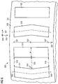
- Fig. 1 illustrates a perspective view of a rotor arrangement 100 according to an embodiment of the present invention.
- the rotor arrangement 100 comprises a support structure 101, which provides a mounting surface 103 extending in an axial direction 105 and in a circumferential direction 107, wherein the support structure is intended to be rotated around a rotation axis 109 which runs along the axial direction 105.
- the support structure 101 is circular in shape and has a cylindrical configuration.
- the radial direction 108 is indicated in Fig. 1 as pointing from the center 110 of the circle 112 outwards towards the mounting surface 103 of the support structure 101.
- the rotor arrangement 100 comprises a first permanent magnet system 111 which is mounted at the mounting surface 103 at a first circumferential region 113. Further, the rotor arrangement 100 comprises a second permanent magnet system 115 which is arranged at the mounting surface 103 at a second circumferential region 117. In particular, the first permanent magnet system 111 is adjacent to the second permanent magnet system 115.
- a first circumferential distance 119 between the first permanent magnet system 111 and the second permanent magnet system 115 at a first axial position 121 differs from a second circumferential distance 125 between the first permanent magnet system 111 and the second permanent magnet system 115 at a second axial position 127.
- the circumferential distance 121 is smaller than the circumferential distance 125 such that the first permanent magnet system 111 is non-parallel to the second permanent magnet system 115.
- the first permanent magnet system is comprised of a single permanent magnet having a first main extension direction 129 and also the second permanent magnet system 115 is constituted by a single permanent magnet having a second main extension direction 131.
- the first main extension direction 129 may be constructed or defined as a best fitting line through cross-sectional centers (either geometrical centers or magnetic centers or mass centers) of the first permanent magnet system 111.
- the second main extension direction of the second permanent magnet system 115 may be defined or constructed as a best fitting line through plural cross-sectional centers (either geometrical centers or magnetic centers or mass centers) of the second permanent magnet system 115.
- the first main extension direction 129 of the first permanent magnet system 111 deviates from the axial direction 105 by an angle ⁇ 1 and the second main extension direction 131 deviates from the axial direction 105 by the skew angle ⁇ 2 .
- the rotor arrangement 100 comprises further permanent magnet systems which are evenly distributed along the circumferential direction 107 at the mounting surface 103 which, however, are not illustrated in Fig. 1 .
- the rotor arrangement 100 may for example be used as an outer rotor in an electrical generator which is in particular employed in a wind turbine.
- Fig. 2 illustrates a schematic perspective view representing a portion of a generator 200, in particular using the rotor arrangement 100 illustrated in Fig. 1 .
- the generator 200 illustrated in Fig. 2 comprises the rotor arrangement 100 illustrated in Fig. 1 and further a stator portion 250 comprising a yoke 251 having plural teeth 253 for forming slots 255 between adjacent teeth 253.
- the distance between adjacent teeth 253 i.e. the tooth pitch
- ⁇ s The distance between adjacent teeth 253 (i.e. the tooth pitch) is denoted as ⁇ s , as is indicated in Fig. 2 .
- Around the teeth, i.e. within the slots 255 wires are wound for forming coils which are, however, not illustrated in Fig. 2 .
- the first permanent magnet system 111 and the second permanent magnet system 115 together form a magnet pole pair.
- the width of the first permanent magnet system 111 is indicated as w.
- Fig. 2 also the axial direction 105, the circumferential direction 107 and the radial direction 108 are indicated.
- the first permanent magnet system 111 has its north pole 131 arranged radially outwards from its south pole 132 and the second permanent magnet system 115 has its south pole 133 radially positioned outwards from its north pole 134.
- the quantity ⁇ p indicated in Fig. 2 is also called the pole pitch relating not to the physical extent of the magnetic system (which is denoted as w) but relating to the magnetic extent of the magnet system in the circumferential direction 107.
- the period of the magnetic field generated by the first permanent magnet system and the second permanent magnet system 115 corresponds to two times ⁇ p .
- Fig. 3 schematically illustrates a view of a projection in the radial direction 208 of a rotor arrangement 200 according to an embodiment of the present invention.
- the rotor arrangement 200 comprises a first permanent magnet 211 having a first main extension direction 229, which is inclined relative to the axial direction by an angle ⁇ 1 . Further, the rotor arrangement 200 comprises a second permanent magnet 215 having a second main extension direction 231 which is inclined relative to the axial direction 205 by an angle ⁇ 2 . Further, the rotor arrangement 300 comprises a third permanent magnet 235 having a main extension direction 236 which is inclined relative to the axial direction 205 by an angle ⁇ 3 . Further, the rotor arrangement 300 comprises a fourth permanent magnet 237 having a main extension direction 238 which is inclined relative to the axial direction 205 by an angle ⁇ 4 .
- a first circumferential distance 219 between the first permanent magnet 211 at a first axial position 221 is smaller than a circumferential distance 225 between the first permanent magnet 211 and the second permanent magnet 215 at a second axial position 227.
- the circumferential distance 219 equals or corresponds to a circumferential distance between the second permanent magnet 215 and the third permanent magnet 235 at the second axial position 227 and also the circumferential distance 219 equals or corresponds to the circumferential distance between the third permanent magnet 235 and the fourth permanent magnet 237 at the first axial position 221.
- the circumferential distance 219 at the first axial position 221 increases linearly to the circumferential distance 225 at the second axial position 227.
- the circumferential distance 225 corresponds or equals to the circumferential distance between the second permanent magnet 215 and the third permanent magnet 235 at the first axial position 221. Further, the circumferential distance 225 equals or corresponds to the circumferential distance between the third permanent magnet 235 and the fourth permanent magnet 237 at the second axial position 227.
- the magnet pole pair formed by the first permanent magnet 211 and the second permanent magnet 215 is rotationally symmetry related to the further magnet pole pair formed by the third permanent magnet 235 and the fourth permanent magnet 237.
- the indicated forces F 1 , F 2 , F 3 , F 4 , F 5 , F 6 , F 7 and F 8 denote forces during operation of the rotor arrangement 200 used in an electromechanical transducer, wherein the forces F 1 , F 3 , F 6 and F 8 denote forces directed radially outwards, while the forces F 2 , F 4 , F 5 and F 7 denote forces pointing radially inwards.
- the forces acting on a single magnet system cancel out, e.g. the forces F 1 (pointing radially outward) and F 5 (pointing radially inwards) act on the first permanent magnet 211, thus result in a net force of zero.
- the skew angles have alternatingly changing signs.
- the force vector F 1 -F 8 balance out in the circumferential direction 207 as well as in the axial direction 205.
- the axial vibration mode may change from (1,1) in a conventional skew to (2P,1) in the proposed non-parallel skew, where P is the number of magnet poles in the complete rotor arrangement.
- the edge of the magnets may become closer together at one end and farther apart from each other at the other end.
- the ratio w/ ⁇ p should generally be chosen to be very high to give maximum generator output.
- the non-parallel arrangement of adjacent permanent magnet as illustrated for example in Fig. 3 or in Figs. 4 to 6 , may impose a limitation to the ratio w/ ⁇ p in order to avoid collision of the edges of adjacent magnets. Thereby, the generator output may be reduced.
- Fig. 5 illustrates a rotor arrangement 400 in a radial projection according to an embodiment of the present invention.
- the rotor arrangement 400 comprises a first permanent magnet 411, a second permanent magnet 415, a third permanent magnet 435 and a fourth permanent magnet 437, which are arranged at a same axial region between the first axial position 421 and the second axial position 427.
- All permanent magnets 411, 415, 435, 437 illustrated in Fig. 5 comprise a first section and a second section, wherein the first section is arranged between the first axial position 421 and the third axial position 422 and the second section is arranged between the third axial position 422 and the second axial position 427.
- first section 439 and the second section 441 of the first permanent magnet 411 are illustrated in Fig. 5 .
- a kink 443 is provided between the first section 439 and the second section 441 of the first permanent magnet 411 , at which the extension direction changes.
- the first section 439 extends along a main extension direction 445 which is inclined relative to the axial direction 405 by an angle ⁇ 11 .
- the second permanent magnet 415 has an arrangement resembling a mirror image of the first permanent magnet 411, wherein a (virtual) mirror plane 447 (extending in the axial direction 405 and the radial direction 408) is arranged between the first permanent magnet 411 and the second permanent magnet 415.
- the circumferential distance between the first permanent magnet 411 and the second permanent magnet 415 increases between the first axial position 421 and the third axial position 422 from the value 419 and 425 and then decreases from the third axial position 422 to the second axial position 427 to become the distance 419 again.
- the circumferential distance between two permanent magnets may be measured between edges of the permanent magnet or between respective main extension directions.
- the third permanent magnet 435 and the fourth permanent magnet 437 are rotationally symmetry related to the first permanent magnet 411 and the second permanent magnet 415.
- Fig. 6 schematically illustrates a rotor arrangement 500 comprising a first permanent magnet 511, a second permanent magnet 515, a third permanent magnet 535 and a fourth permanent magnet 537.
- the first permanent magnet 511 has a same configuration as the first permanent magnet 411 of the embodiment illustrated in Fig. 5 .
- the second permanent magnet 515 has the same configuration and arrangement as the second permanent magnet 315 illustrated in Fig. 4 . Thereby, in particular a width w of the permanent magnet may be increased, while maintaining reduction of undesired vibration modes.
- All permanent magnets illustrated in Figs. 3 to 6 may also be constituted from plural individual distinct magnets which are arranged side by side along the axial direction or along the respective main extension direction. Thereby, the circumferential distance between two neighbouring permanent magnet systems may in particular change in a step-wise manner.
- the permanent magnet may comprise more than one kink such that for example the permanent magnets comprise plural axial sections having alternating main extension directions, thereby forming a zigzag structure.
Description
- The present invention relates to a rotor arrangement and to an electromechanical transducer, in particular a generator, wherein permanent magnets are arranged in a non-parallel manner skewed or inclined relative to an axial direction.
- An electromechanical transducer, such as an electro motor or a generator converts mechanical energy (in particular rotational energy) into electrical energy or vice versa. Thereby, a stator portion may comprise annularly arranged teeth around which conductors are wound to form plural annularly arranged coils. In particular, the teeth and the coils may be arranged in a cylindrical configuration.
- A rotor arrangement may rotate around an axis at the center of the circle relative to the stator portion. The rotor arrangement may comprise plural permanent magnets or permanent magnet systems. Upon rotation of the rotor arrangement relative to the stator, voltages may be induced in the coils due to the moving permanent magnets. The induced voltages may provide electric energy.
- In the electromechanical transducer or in the electrical machine a number of vibrations or vibrational modes may occur during operation. The vibration may be due to the interaction of the magnetic flux waves with the stator slotting, i.e. cogging torque. A conventional method to reduce such vibration, in particular torsional vibration, is to skew or incline the magnets with respect to the axial direction with an appropriate skew angle which may be based on the tooth pitch of the stator portion.
- Document
EP 0 718 959 A2 discloses a Lundell-type rotor assembly for hybrid alternator, wherein the alternator has an inner rotor with a plurality of permanent magnets disposed between opposing claw-pole members and a field coil, wherein the magnets are located into appropriate positions between the fingers of the claw-pole members. - However, it has been observed that the conventional electrical machine or conventional electromechanical transducer or conventional rotor arrangement used for an electromechanical transducer is not capable to reduce all kinds of vibration occuring during operation appropriately. In particular, the conventional electromechanical transducer may still exhibit a significant axial vibration during operation.
- There may be a need for a rotor arrangement and for an electromechanical transducer, in particular generator, wherein vibration of the electromechanical transducer is reduced and wherein in particular a reduced axial vibration occurs.
- The need is satisfied by the subject matter of independent claim 1. The dependent claims specify advantageous embodiments of the present invention.
- According to an embodiment of the present invention it is provided a rotor arrangement, comprising: a support structure providing a mounting surface extending in an axial direction and a circumferential direction, the support structure being adapted to rotate around the axial direction; a first permanent magnet system arranged at the mounting surface at a first circumferential region; a second permanent magnet system arranged at the mounting surface at a second circumferential region; wherein a circumferential distance between the first magnet system and the second magnet system at a first axial position differs from the circumferential distance between the first magnet system and the second magnet system at a second axial position.
- The rotor arrangement may be used in an electromechanical transducer, such as an electromotor or an electric generator.
- The electric generator may in particular be used for a wind turbine in order to convert the mechanical energy resulting from impact of wind onto plural rotor blades to electrical energy which may then be supplied to a utility grid, which may then in turn provide the electrical energy to a plurality of consumers.
- In particular, the rotor arrangement may constitute a circumferential section from which an annular rotor arrangement may be assembled. Alternatively, the rotor arrangement may represent a complete annular structure, in particular a cylindrical structure having as a principal (cross-sectional) shape a circular shape.
- The support structure may be provided for supporting or holding or mounting the permanent magnet systems. The axial direction may correspond (or may be parallel) to a rotational axis around which the rotor arrangement is intended to be rotated during operation, when the rotor arrangement is used for or assembled into an electromechanical transducer. The circumferential direction is perpendicular to the axial direction and a radial direction is perpendicular to the axial direction and also perpendicular to the circumferential direction.
- In a complete annular rotor arrangement plural permanent magnet systems may be arranged side by side along the circumferential direction in order to be evenly spaced apart and in order to be distributed evenly around the entire circumference, i.e. the circular circumference of the complete rotor arrangement. In particular, the rotor arrangement may be either an outer rotor arrangement, in which the rotor arrangement is intended to be arranged radially outwards from a stator portion, or may be adapted as an inner rotor arrangement, which is intended to be arranged radially inwards relative to a stator, when assembled into an electromechanical transducer.
- The first (and/or the second) permanent magnet system may either be constituted by a single integrally formed magnet or may be constituted by a plurality of individual magnets which are arranged side by side, in particular adjacent to each other, along the axial direction or along a direction inclined relative to the axial direction. The first permanent magnet system as well as the second permanent magnet system may be fixed to the amounting surface using appropriate fixing equipment, such as skews or boles.
- In particular, the first permanent magnet system may be assigned a first main extension direction being the direction along which the first permanent magnet system extends. Thereby, the main extension direction may be defined by a straight line, which best fits plural cross-sectional centers of plural axial cross-sections of the first permanent magnet system. Thereby, the cross-section center may be in particular defined as a geometrical cross-sectional center or a mass center or magnetic center of the considered axial cross-section of the first permanent magnet system. In particular, the first main extension direction of the first permanent magnet system may either be parallel to the axial direction or may be inclined relative to the axial direction by a skew angle defining a deviation of the first main extension direction in the circumferential direction with respect to the axial direction.
- A second main extension direction may also assigned to the second permanent magnet system in an analogous way. In particular, the second main extension direction may be parallel to the axial direction or may be inclined relative to the axial direction by (in particular another) skew angle defining a deviation of the second main extension direction in the circumferential direction from the axial direction.
- In particular, the first permanent magnet system and the second permanent magnet system may be arranged at the mounting surface such that the first main extension direction is not parallel to the second main extension direction. The distance between the first magnet system and the second magnet system at a particular axial position may relate to a distance between the cross-sectional center of the first magnet system and the cross-sectional center of the second magnet system at the considered axial position or may relate to a distance between an edge of the first magnet system and an edge of the second magnet system. Further, the distance between the first magnet system and the second magnet system may relate or may be equal to a distance between a magnetic center of a cross-section of the first magnet system at the considered axial position and a magnetic center of a cross-section of the second magnet system at the considered axial position.
- Due to the different circumferential distances between the first magnet system and the second magnet system at the first axial position and the second axial position, respectively, the first magnet system and the second magnet system do not run parallel to each other, in particular the first main extension direction does not run parallel to the second main extension direction.
- With such an arrangement of the first permanent magnet system and the second permanent magnet system a torsional vibration of an electromechanical transducer may be reduced, while no significant axial vibration is caused. In particular, the first permanent magnet system and the (circumferentially adjacent) second permanent magnet system may form a magnet pole pair.
- According to an embodiment of the present invention the first permanent magnet system is inclined with respect to the axial direction in the circumferential direction, in particular by a skew angle, wherein the second permanent magnet system is inclined with respect to the axial direction in an opposite circumferential direction, in particular by the skew angle.
- In particular, the first main extension direction of the first permanent magnet system may be inclined with respect to the axial direction in the circumferential direction and in particular the second main extension direction of the second permanent magnet system may be inclined with respect to the axial direction in an opposite circumferential direction. Further, the inclination relative to the axial direction may have a same amount but may have different sign, i.e. when the first permanent magnet system is inclined by an angle +Φ relative to the axial direction the second permanent magnet system may be inclined with the angle -Φ relative to the axial direction.
- In this particular configuration or arrangement of the permanent magnet systems the tangential force component due to magnet flux interaction with the stator slotting may be balanced out along the axial length, resulting in zero or very small net resultant force in the tangential (circumferential) direction, minimizing the torsional vibration and acoustic noise emission. Thus, forces acting on the first permanent magnet system in the radial direction may be cancelled out when summing all forces along the extension of the first permanent magnet system. Further, also all forces, in particular radial forces acting on the second permanent magnet system may be cancelled out, when summing all forces along the extension of the second permanent magnet system.
- In addition and in particular in contrast to a conventional system, also the forces exerted on the (neighbouring or adjacent) first permanent magnet system and the second permanent magnet system at a-particular axial position may cancel out due to the inclination of the first permanent magnet system and the second permanent magnet system in different directions relative to the axial direction. I.e., when considering a particular axial position, the (radial) forces acting on the plural magnet system of the rotor arrangement may cancel out, when summing along the circumferential direction (over at least two or plural magnet systems). Thereby, a global axial vibration of the rotor structure may be reduced. In particular, a circumferential mode of order "1" or a vibration according to a circumferential mode of order "1" may be reduced, since the excitation forces of all permanent magnets in the circumferential direction do not have the same orientation anymore (i.e. either all pointing radially outwards or all pointing radially inwards) but have alternating orientations, such that one force at the first permanent magnet system may point radially outwards and the force acting on the second permanent magnet system may point radially inwards, such that a net force of zero results, when summing around or along the circumferential direction.
- Thus, a lower order vibration mode (i.e. the circumferential vibration mode of order "1") may be reduced, which may increase the stiffness of the structure, in order to reduce vibration amplitude and acoustic noise emission. Further, a (1,1) vibration mode, the first element indicating the circumferential mode and the second element indicating the axial mode of vibration may be reduced. In particular, the axial vibration may be significantly reduced.
- In a conventional Herring-Bone magnet arrangement, the magnets are skewed relative to the axial direction, but the magnets are oriented parallel to each other. The conventional Herring-Bone configuration increases the mode of the axial exciting force/vibration from (1,1) to (1,2) in which the force vectors change directions twice along the axial length of each magnet pole. As a result of the mode increase or the increase of the order of the mode, the axial vibration may be reduced according to this conventional configuration.
- However, even though the Herring-Bone skew configuration may reduce the axial vibration, the configuration according to the embodiment of the present invention may even further reduce the axial vibration. Further, the non-parallel arrangement of the adjacent first permanent magnet system and the second permanent magnet system may be combined with the Herring-Bone skew configuration, thereby increasing its effectiveness in reducing the axial vibration.
- According to an embodiment of the present invention the circumferential distance increases continuously, in particular linearly, or in a step-wise manner from the first axial position to the second axial position. When the first permanent magnet system is constituted by a single integrally formed magnet, the circumferential distance may increase continuously. In particular, the increase of the circumferential distance may be linear with the axial position such that the circumferential distance may be calculated as a constant factor times the axial position plus a constant. In contrast, when the first permanent magnet system is constituted by plural individual permanent magnets the circumferential distance may increase in a step-wise manner. Thereby, a simple way to achieve the rotor arrangement may be provided.
- According to an embodiment of the present invention the circumferential distance increases continuously, in particular linearly, or in a step-wise manner from the first axial position to a third axial position, wherein the distance decreases continuously, in particular linearly, or in a step-wise manner from the third axial position to the second axial position.
- Thus, the circumferential distance increases between the first axial position and the third axial position and then decreases from the third axial position to the second axial position. Thereby, the Herring-Bone type configuration may be adapted according to the non-parallel arrangement of the first permanent magnet system and the second permanent magnet system according to an embodiment of the present invention. Thereby, the axial vibration may further be reduced.
- According to an embodiment of the present invention the first permanent magnet system and the second permanent magnet system extend at the mounting surface across a same axial region.
- Thus, in particular, the first permanent magnet system and the second permanent magnet system may be (immediately) adjacent along the circumferential direction and may span or occupy a same axial region which may be for example defined as the axial range between the first axial position and the second axial position. Alternatively, the first axial position and the second axial position may be somewhere in between limiting axial positions bordering the axial region. Mounting the first permanent magnet system and the second permanent magnet system at the same axial region may cause an effective cancelling out of (radial) force components when summing along the circumferential direction. Thereby, the reduction of the axial vibration may even further be improved.
- According to an embodiment of the present invention the first permanent magnet system comprises at least a first part arranged at the first axial position and a second part arranged at the second axial position and/or wherein the second permanent magnet system comprises at least a first part arranged at the first axial position and a second part arranged at the second axial position.
- According to this embodiment the first permanent magnet system comprises at least two (in particular a plurality of) parts arranged at different axial positions. Each part of the first permanent magnet system may represent or constitute a single individual permanent magnet, wherein the single permanent magnets are physically separated from each other and are not integrally formed but may constitute distinct physical elements.
- Thereby, a so-called step-wise skew configuration may be achieved, while the first main extension direction and the second main extension direction are not parallel to each other. In particular, the first main extension direction may be defined as a straight line best fitting cross-sectional centers of the first part and the second part (or of the plural parts) of the first permanent magnet system and analogous definition is provided for the second permanent magnet system when comprising a first part and a second part (or plural parts constituting individual distinct permanent magnets).
- Thereby, it may not be necessary to manufacture a single first permanent magnet for constituting the first permanent magnet system which may simplify the manufacturing the rotor arrangement.
- According to an embodiment of the present invention the first permanent magnet system constitutes a single first magnet and/or wherein the second permanent magnet system constitutes a single second magnet.
- Thereby, mounting the first permanent magnet system may be simplified, since it may not be necessary to mount plural parts of the first permanent magnet system. Further, orienting the first permanent magnet system at the mounting surface may be simplified, e.g. by aligning an edge of the first permanent magnet with a line drawn at the mounting surface, wherein this line is inclined relative (or is parallel) to the axial direction.
- According to an embodiment of the present invention the single first magnet has a straight edge, in particular along its entire axial extent, and/or wherein the single second magnet has a straight edge, in particular along its entire axial extent. The magnet having a straight edge may be manufactured in a simple manner. Further, orienting the first magnet and the second magnet at the mounting surface may be simplified by aligning the straight edges with corresponding auxiliary lines drawn at the mounting surface.
- According to an embodiment of the present invention the first magnet comprises a kink between a first section and a second sections, wherein the first section and the second section extend in a different directions, wherein in particular the first section is inclined relative to the axial direction in the circumferential direction, wherein in particular the second section is inclined relative to the axial direction in the opposite circumferential direction or runs along the axial direction, wherein in particular a non-parallel Herring-Bone type arrangement is achieved.
- The first section of the first magnet may span a first axial region and the second section of the first magnet may span a second axial region adjacent to the first axial region. The kink may in particular be arranged at the third axial position. The first section may be arranged between the first axial position and the third axial position and the second section may be arranged between the third axial position and the second axial position.
- Also a first sectional main extension direction may be assigned to the first section of the first magnet and a second sectional main extension direction may be assigned to the second section of the first magnet. In particular, the first sectional main extension direction and the second sectional main extension direction of the first magnet may not be parallel to each other. In particular, the first sectional main extension direction and the second sectional main extension direction of the first magnet may be inclined relative to the axial direction in an opposite fashion in which the inclination may be in the circumferential direction and in the opposite circumferential direction, respectively.
- Thereby, a non-parallel Herring-Bone skew configuration may be achieved. Thereby, the axial vibration may further be reduced, when the rotor arrangement is assembled into an electromechanical transducer.
- According to an embodiment of the present invention the first magnet system and the second magnet system have different magnetic orientations, in particular opposite magnetic orientations. For example, the first magnet system may have a north pole oriented radially inward and a south pole oriented or arranged radially outwards. The second magnet system may have the south pole oriented radially inward and the north pole oriented or arranged radially outwards. Thereby, the first magnet system and the second magnet system may in combination form a magnet pole pair.
- According to an embodiment of the present invention the rotor arrangement further comprises a third permanent magnet system arranged at the mounting surface at a third circumferential region and a fourth permanent magnet system arranged at the mounting surface at a fourth circumferential region, wherein a circumferential distance between the third magnet system and the fourth magnet system at the first axial position differs from the circumferential distance between the first magnet system and the second magnet system at the second axial position, wherein a circumferential distance between the second magnet system and the third magnet system at the first axial position differs from the circumferential distance between the second magnet system and the third magnet system at the second axial position.
- In particular, the third permanent magnet system and the fourth permanent magnet system may constitute a further magnet pole pair being adjacent to the magnet pole pair constituted by the first permanent magnet system and the second permanent magnet system. The magnet pole pair and the further magnet pole pair may be (immediately) adjacent to each other in the circumferential direction.
- In particular, the third permanent magnet system and/or the fourth permanent magnet system may have a same axial extent or may occupy a same axial region as the first permanent magnet system and/or the second permanent magnet system. The magnetic pole pair may be rotationally symmetry related to the further magnet pole pair, but does not need to be rotationally symmetry related.
- In particular, when the magnet pole pair is rotationally symmetry related (with respect to the intended rotation axis of the rotor arrangement) to the further magnet pole pair the circumferential distance between the second magnet system and the third permanent magnet system may decrease from the first axial position to the second axial position. Further, the circumferential distance between the third permanent magnet system and the fourth permanent magnet system may increase from the first axial position to the second axial position. This configuration may in particular be achieved when the second magnet system is rotationally symmetry related around the axial direction to the fourth magnet system and when further the first magnet system is rotationally symmetry related around the axial direction to the third magnet system.
- According to another embodiment of the present invention the second permanent magnet system may be rotationally symmetry related around the axial direction to the fourth permanent magnet system, but the first permanent magnet system may not be rotationally symmetry related around the axial direction to the third permanent magnet system. This may in particular be the case, when the second permanent magnet system is arranged to extend parallel to the axial direction and also when the fourth permanent magnet system is arranged to be parallel to the axial direction. In this configuration, the circumferential distance between the second permanent magnet system and the third permanent magnet system may increase (as the circumferential distance between the first permanent magnet system and the second permanent magnet system) from the first axial position to the second axial position. However, the circumferential distance between the third permanent magnet system and the fourth permanent magnet system may decrease from the first axial position to the second axial position. This configuration is in particular provided, when the first permanent magnet system is not rotationally symmetry related around the axial direction to the third permanent magnet system.
- In particular, according to this last embodiment it may be avoided to reduce the width of the magnet systems too much, thereby increasing the efficiency of the electromechanical transducer, in particular the generator output energy. In particular, it may be avoided that edges of neighbouring permanent magnet systems approach each other.
- According to an embodiment of the present invention it is provided an electromechanical transducer, in particular a generator which comprises a stator having plural teeth having a slot between adjacent teeth and a rotor arrangement according to one of the embodiments described above. In operation vibration of the electromechanical transducer may be reduced due to the particular constitution of the rotor arrangement having non-parallel adjacent permanent magnets.
- According to an embodiment of the present invention the skew angle (or skew angles) defining the orientation or orientation of the permanent magnet systems with respect to the axial direction is selected to reduce axial vibration during operation of the transducer. Finding the optimal skew angle may be a compromise between maximizing the width of the permanent magnet system (in particular circumferential width) (requiring decreasing the skew angle) and reducing the undesired vibrations or vibration modes (requiring increasing the skew angle). Simulations (in particular taking into account the geometry, used materials and intended operation conditions of the transducer) may be performed, in order to determine the optimized skew angle, on one hand improving the efficiency or energy output of the electromechanical transducer and on the other hand reducing vibrations leading to undesired noise emissions.
- According to an embodiment of the present invention the electromechanical transducer is configured as a generator. The generator may be comprised in a wind turbine and may be mechanically connected to a main shaft of the wind turbine at which plural rotor blades are connected.
- Particular embodiments of the present invention are now described with reference to the accompanying drawings. The invention is not limited to the described or illustrated embodiments.
- The aspects defined above and further aspects of the present invention are apparent from the examples of embodiment to be described hereinafter and are explained with reference to the examples of embodiment. The invention will be described in more detail hereinafter with reference to examples of embodiment but to which the invention is not limited.
-
- Fig. 1
- schematically illustrates a perspective view of a rotor arrangement according to an embodiment of the present invention;
- Fig. 2
- schematically illustrates a perspective view of a portion of an electromechanical transducer according to an embodiment of the present invention for definition of parameters;
- Fig. 3
- schematically illustrates a schematic view of a radial projection of a portion of a rotor arrangement according to an embodiment of the present invention;
- Fig. 4
- schematically illustrates a schematic view of a radial projection of a portion of a rotor arrangement according to an embodiment of the present invention;
- Fig. 5
- schematically illustrates a schematic view of a radial projection of a portion of a rotor arrangement according to an embodiment of the present invention; and
- Fig. 6
- schematically illustrates a schematic view of a radial projection of a portion of a rotor arrangement according to an embodiment of the present invention.
-
Fig. 1 illustrates a perspective view of arotor arrangement 100 according to an embodiment of the present invention. Therotor arrangement 100 comprises asupport structure 101, which provides a mountingsurface 103 extending in anaxial direction 105 and in acircumferential direction 107, wherein the support structure is intended to be rotated around arotation axis 109 which runs along theaxial direction 105. In particular, thesupport structure 101 is circular in shape and has a cylindrical configuration. Theradial direction 108 is indicated inFig. 1 as pointing from thecenter 110 of thecircle 112 outwards towards the mountingsurface 103 of thesupport structure 101. - The
rotor arrangement 100 comprises a firstpermanent magnet system 111 which is mounted at the mountingsurface 103 at a firstcircumferential region 113. Further, therotor arrangement 100 comprises a secondpermanent magnet system 115 which is arranged at the mountingsurface 103 at a secondcircumferential region 117. In particular, the firstpermanent magnet system 111 is adjacent to the secondpermanent magnet system 115. - A first
circumferential distance 119 between the firstpermanent magnet system 111 and the secondpermanent magnet system 115 at a first axial position 121 (along aline 123 running in theaxial direction 105 or at least being parallel to the rotation axis 109) differs from a secondcircumferential distance 125 between the firstpermanent magnet system 111 and the secondpermanent magnet system 115 at a secondaxial position 127. - In particular, the
circumferential distance 121 is smaller than thecircumferential distance 125 such that the firstpermanent magnet system 111 is non-parallel to the secondpermanent magnet system 115. In particular, the first permanent magnet system is comprised of a single permanent magnet having a firstmain extension direction 129 and also the secondpermanent magnet system 115 is constituted by a single permanent magnet having a second main extension direction 131. The firstmain extension direction 129 may be constructed or defined as a best fitting line through cross-sectional centers (either geometrical centers or magnetic centers or mass centers) of the firstpermanent magnet system 111. Further, the second main extension direction of the secondpermanent magnet system 115 may be defined or constructed as a best fitting line through plural cross-sectional centers (either geometrical centers or magnetic centers or mass centers) of the secondpermanent magnet system 115. - As is apparent from
Fig. 1 the firstmain extension direction 129 of the firstpermanent magnet system 111 deviates from theaxial direction 105 by an angle Φ1 and the second main extension direction 131 deviates from theaxial direction 105 by the skew angle Φ2. In particular, the angles Φ1, Φ2 are inclined relative to theaxial direction 105 in an opposite way (Φ1 = -Φ2), thereby causing the different circumferential distances between the firstpermanent magnet system 111 and the secondpermanent magnet system 115 at the firstaxial position 121 and the secondaxial position 127, respectively. Therotor arrangement 100 comprises further permanent magnet systems which are evenly distributed along thecircumferential direction 107 at the mountingsurface 103 which, however, are not illustrated inFig. 1 . - The
rotor arrangement 100 may for example be used as an outer rotor in an electrical generator which is in particular employed in a wind turbine. -
Fig. 2 illustrates a schematic perspective view representing a portion of agenerator 200, in particular using therotor arrangement 100 illustrated inFig. 1 . Thegenerator 200 illustrated inFig. 2 comprises therotor arrangement 100 illustrated inFig. 1 and further astator portion 250 comprising ayoke 251 havingplural teeth 253 for formingslots 255 betweenadjacent teeth 253. The distance between adjacent teeth 253 (i.e. the tooth pitch) is denoted as τs, as is indicated inFig. 2 . Around the teeth, i.e. within theslots 255 wires are wound for forming coils which are, however, not illustrated inFig. 2 . - The first
permanent magnet system 111 and the secondpermanent magnet system 115 together form a magnet pole pair. The width of the firstpermanent magnet system 111 is indicated as w. - In
Fig. 2 also theaxial direction 105, thecircumferential direction 107 and theradial direction 108 are indicated. The firstpermanent magnet system 111 has its north pole 131 arranged radially outwards from itssouth pole 132 and the secondpermanent magnet system 115 has itssouth pole 133 radially positioned outwards from itsnorth pole 134. The quantity τp indicated inFig. 2 is also called the pole pitch relating not to the physical extent of the magnetic system (which is denoted as w) but relating to the magnetic extent of the magnet system in thecircumferential direction 107. In particular, the period of the magnetic field generated by the first permanent magnet system and the secondpermanent magnet system 115 corresponds to two times τp. - In
Figs. 3 to 6 an element or a structures which is similar in structure and/or functions to an element illustrated inFig. 1 is denoted with same reference sign differing only in the first digit. Description of these corresponding elements can therefore be taken from the description of the corresponding elements described with reference toFig. 1 . -
Fig. 3 schematically illustrates a view of a projection in theradial direction 208 of arotor arrangement 200 according to an embodiment of the present invention. - The
rotor arrangement 200 comprises a firstpermanent magnet 211 having a firstmain extension direction 229, which is inclined relative to the axial direction by an angle Φ1. Further, therotor arrangement 200 comprises a secondpermanent magnet 215 having a secondmain extension direction 231 which is inclined relative to theaxial direction 205 by an angle Φ2. Further, therotor arrangement 300 comprises a thirdpermanent magnet 235 having amain extension direction 236 which is inclined relative to theaxial direction 205 by an angle Φ3. Further, therotor arrangement 300 comprises a fourthpermanent magnet 237 having amain extension direction 238 which is inclined relative to theaxial direction 205 by an angle Φ4. - Thereby, a first
circumferential distance 219 between the firstpermanent magnet 211 at a firstaxial position 221 is smaller than acircumferential distance 225 between the firstpermanent magnet 211 and the secondpermanent magnet 215 at a secondaxial position 227. Further, according to this embodiment illustrated inFig. 3 thecircumferential distance 219 equals or corresponds to a circumferential distance between the secondpermanent magnet 215 and the thirdpermanent magnet 235 at the secondaxial position 227 and also thecircumferential distance 219 equals or corresponds to the circumferential distance between the thirdpermanent magnet 235 and the fourthpermanent magnet 237 at the firstaxial position 221. - Further, as can be seen from
Fig. 3 , thecircumferential distance 219 at the firstaxial position 221 increases linearly to thecircumferential distance 225 at the secondaxial position 227. - Further, the
circumferential distance 225 corresponds or equals to the circumferential distance between the secondpermanent magnet 215 and the thirdpermanent magnet 235 at the firstaxial position 221. Further, thecircumferential distance 225 equals or corresponds to the circumferential distance between the thirdpermanent magnet 235 and the fourthpermanent magnet 237 at the secondaxial position 227. - In particular, the magnet pole pair formed by the first
permanent magnet 211 and the secondpermanent magnet 215 is rotationally symmetry related to the further magnet pole pair formed by the thirdpermanent magnet 235 and the fourthpermanent magnet 237. - In
Fig. 3 the indicated forces F1, F2, F3, F4, F5, F6, F7 and F8 denote forces during operation of therotor arrangement 200 used in an electromechanical transducer, wherein the forces F1, F3, F6 and F8 denote forces directed radially outwards, while the forces F2, F4, F5 and F7 denote forces pointing radially inwards. As is apparent from the illustrated forces inFig. 3 the forces acting on a single magnet system cancel out, e.g. the forces F1 (pointing radially outward) and F5 (pointing radially inwards) act on the firstpermanent magnet 211, thus result in a net force of zero. - Further, as is apparent from
Fig. 3 forces acting at a particular axial position (for example between theposition - In particular, the angles are Φ1 = -Φ2 and Φ3 = -Φ4 and Φ1 = Φ3. Thus, the skew angles have alternatingly changing signs. Thereby, the force vector F1-F8 balance out in the
circumferential direction 207 as well as in theaxial direction 205. In other words, the axial vibration mode may change from (1,1) in a conventional skew to (2P,1) in the proposed non-parallel skew, where P is the number of magnet poles in the complete rotor arrangement. Since the achieved mode of axial vibration based on the embodiment of the present invention is much larger than that obtained from a conventional Herring-Bone skew, it is realized that the damping of axial vibration obtained by the non-parallel skew may be much more significant or effective. - By skewing the magnet following the proposed non-parallel arrangement the edge of the magnets may become closer together at one end and farther apart from each other at the other end. Usually, the ratio w/τp, as illustrated in
Fig. 2 , should generally be chosen to be very high to give maximum generator output. However, the non-parallel arrangement of adjacent permanent magnet as illustrated for example inFig. 3 or inFigs. 4 to 6 , may impose a limitation to the ratio w/τp in order to avoid collision of the edges of adjacent magnets. Thereby, the generator output may be reduced. - However, by appropriate simulation an optimal compromise between maximizing the width w and avoiding undesired vibrations may be obtained.
- Further, in order to reduce the limiting effect or limiting factor and in order to keep the width w as large as possible a configuration as illustrated in
Fig. 4 (orFig. 6 ) is proposed. Therotor arrangement 300 illustrated inFig. 4 (also as a radial projection in a schematic way) comprises the firstpermanent magnet 311 inclined relative to theaxial direction 305 by the angle Φ1, the secondpermanent magnet 315 having itsmain extension direction 331 aligned with and thus parallel to theaxial direction 305, a thirdpermanent magnet 335 having itsmain extension direction 336 inclined by an angle Φ3 relative to the axial direction, and the fourthpermanent magnet 337 having itsmain extension direction 338 aligned parallel to theaxial direction 305. Further, in this embodiment Φ1 = -Φ3. Thereby, the width w of the permanent magnet may be increased while still reducing undesired vibrations. -
Fig. 5 illustrates arotor arrangement 400 in a radial projection according to an embodiment of the present invention. Therotor arrangement 400 comprises a firstpermanent magnet 411, a secondpermanent magnet 415, a thirdpermanent magnet 435 and a fourthpermanent magnet 437, which are arranged at a same axial region between the firstaxial position 421 and the secondaxial position 427. Allpermanent magnets Fig. 5 comprise a first section and a second section, wherein the first section is arranged between the firstaxial position 421 and the thirdaxial position 422 and the second section is arranged between the thirdaxial position 422 and the secondaxial position 427. - For clarity only the
first section 439 and thesecond section 441 of the firstpermanent magnet 411 are illustrated inFig. 5 . Between thefirst section 439 and thesecond section 441 of the first permanent magnet 411 akink 443 is provided, at which the extension direction changes. In particular, thefirst section 439 extends along amain extension direction 445 which is inclined relative to theaxial direction 405 by an angle Φ11. Further, themain extension direction 446 of thesecond section 441 of thefirst magnet 411 is inclined relative to theaxial direction 405 by an angle Φ12, wherein Φ11 = -Φ12. - The second
permanent magnet 415 has an arrangement resembling a mirror image of the firstpermanent magnet 411, wherein a (virtual) mirror plane 447 (extending in theaxial direction 405 and the radial direction 408) is arranged between the firstpermanent magnet 411 and the secondpermanent magnet 415. - Further, the circumferential distance between the first
permanent magnet 411 and the secondpermanent magnet 415 increases between the firstaxial position 421 and the thirdaxial position 422 from thevalue axial position 422 to the secondaxial position 427 to become thedistance 419 again. Thereby, the circumferential distance between two permanent magnets may be measured between edges of the permanent magnet or between respective main extension directions. - The third
permanent magnet 435 and the fourthpermanent magnet 437 are rotationally symmetry related to the firstpermanent magnet 411 and the secondpermanent magnet 415. -
Fig. 6 schematically illustrates arotor arrangement 500 comprising a firstpermanent magnet 511, a secondpermanent magnet 515, a thirdpermanent magnet 535 and a fourthpermanent magnet 537. The firstpermanent magnet 511 has a same configuration as the firstpermanent magnet 411 of the embodiment illustrated inFig. 5 . Further, the secondpermanent magnet 515 has the same configuration and arrangement as the secondpermanent magnet 315 illustrated inFig. 4 . Thereby, in particular a width w of the permanent magnet may be increased, while maintaining reduction of undesired vibration modes. - All permanent magnets illustrated in
Figs. 3 to 6 may also be constituted from plural individual distinct magnets which are arranged side by side along the axial direction or along the respective main extension direction. Thereby, the circumferential distance between two neighbouring permanent magnet systems may in particular change in a step-wise manner. According to another embodiment the permanent magnet may comprise more than one kink such that for example the permanent magnets comprise plural axial sections having alternating main extension directions, thereby forming a zigzag structure. - It should be noted that the term "comprising" does not exclude other elements or steps and "a" or "an" does not exclude a plurality. Also elements described in association with different embodiments may be combined. It should also be noted that reference signs in the claims should not be construed as limiting the scope of the claims.
Claims (15)
- Outer rotor arrangement (100, 200, 300, 400, 500), comprising:a support structure (101) providing a mounting surface (103) extending in an axial direction (105) and a circumferential direction (107), the support structure being adapted to rotate around the axial direction (105, 109);a first permanent magnet system (111) arranged at the mounting surface at a first circumferential region (113);a second permanent magnet system (115) arranged at the mounting surface at a second circumferential region (117);wherein a circumferential distance (119) between the first magnet system and the second magnet system at a first axial position (121) differs from the circumferential distance (125) between the first magnet system and the second magnet system at a second axial position (127),wherein the first magnet system (411) comprises a kink (443) between a first section (439) and a second sections (441), wherein the first section and the second section extend in different directions (445, 446).
- Outer rotor arrangement according to claim 1, wherein the first permanent magnet system is inclined (Φ1) with respect to the axial direction in the circumferential direction, in particular by a skew angle (Φ1),
wherein the second permanent magnet system is inclined (Φ2) with respect to the axial direction in an opposite circumferential direction, in particular by the skew angle (Φi). - Outer rotor arrangement according to claim 1 or 2, wherein the circumferential distance (119, 125) increases continuously, in particular linearly, or in a step-wise manner from the first axial position (121) to the second axial position (127).
- Outer rotor arrangement according to one of the preceding claims, wherein the circumferential distance increases continuously, in particular linearly, or in a step-wise manner from the first axial position (421) to a third axial position (422),
wherein the distance decreases continuously, in particular linearly, or in a step-wise manner from the third axial position (422) to second axial position (427). - Outer rotor arrangement according to one of the preceding claims, wherein the first permanent magnet system (111) and the second permanent magnet system (115) extends at the mounting surface (103) across a same axial region (121,127).
- Outer rotor arrangement according to one of the preceding claims, wherein the first permanent magnet system comprises at least a first part arranged at the first axial position and a second part arranged at the second axial position and/or
wherein the second permanent magnet system comprises at least a first part arranged at the first axial position and a second part arranged at the second axial position. - Outer rotor arrangement according to one of claims 1 to 5, wherein the first permanent magnet system constitutes a single first magnet (111) and/or
wherein the second permanent magnet system constitutes a single second magnet (115). - Outer rotor arrangement according to claim 7, wherein the single first magnet has a straight edge, in particular along its entire axial extent, and/or
wherein the single second magnet has a straight edge, in particular along its entire axial extent. - Outer rotor arrangement according to claim 7 or 8, wherein the first section is inclined (Φ11) relative to the axial direction (405) in the circumferential direction (407), wherein the second section is inclined (Φ11) relative to the axial direction (405) in the opposite circumferential direction or runs along the axial direction (405),
wherein in particular a non-parallel Herring-Bone type arrangement is achieved. - Outer rotor arrangement according to one of the preceding claims, wherein the first magnet system (111) and the second magnet system (115) have different magnetic orientations (131, 132, 133, 134), in particular opposite magnetic orientations.
- Outer rotor arrangement according to one of the preceding claims, further comprising:a third permanent magnet system (235) arranged at the mounting surface (203) at a third circumferential region;a fourth permanent magnet system (237) arranged at the mounting surface (203) at a fourth circumferential region;wherein a circumferential distance between the third magnet system and the fourth magnet system at the first axial position differs from the circumferential distance between the first magnet system and the second magnet system at the second axial position,wherein a circumferential distance between the second magnet system and the third magnet system at the first axial position differs from the circumferential distance between the second magnet system and the third magnet system at the second axial position.
- Outer rotor arrangement according to claim 11, wherein the second magnet system (215, 315, 415, 515) is rotationally symmetry related around the axial direction to the fourth magnet system (237, 337, 437, 537).
- Outer rotor arrangement according to claim 11 or 12, wherein the first magnet system is (211, 411) or is not (311, 511) rotationally symmetry related around the axial direction to the third magnet system (235, 335, 435, 535).
- Electromechanical transducer (200), in particular generator, comprising:a stator (250) having plural teeth (253) having a slot (255) between adjacent teeth (253);an outer rotor arrangement (100, 200, 300, 400, 500) according to one of the preceding claims.
- Electromechanical transducer according to claim 14, wherein a skew angle (Φ) is selected based on a simulation taking into account geometry, used materials and intended operation conditions of the transducer.
Priority Applications (4)
| Application Number | Priority Date | Filing Date | Title |
|---|---|---|---|
| DK12164938.8T DK2654181T3 (en) | 2012-04-20 | 2012-04-20 | Rotor device and electromechanical transducer with non-parallel permanent magnets |
| EP12164938.8A EP2654181B1 (en) | 2012-04-20 | 2012-04-20 | Rotor arrangement and electromechanical transducer having non-parallel permanent magnets |
| US13/865,364 US9419480B2 (en) | 2012-04-20 | 2013-04-18 | Rotor arrangement and electromechanical transducer having non-parallel permanent magnets |
| CN201310137533.XA CN103378674B (en) | 2012-04-20 | 2013-04-19 | Rotor with not parallel permanent magnet is set and electromechanical transducer |
Applications Claiming Priority (1)
| Application Number | Priority Date | Filing Date | Title |
|---|---|---|---|
| EP12164938.8A EP2654181B1 (en) | 2012-04-20 | 2012-04-20 | Rotor arrangement and electromechanical transducer having non-parallel permanent magnets |
Publications (2)
| Publication Number | Publication Date |
|---|---|
| EP2654181A1 EP2654181A1 (en) | 2013-10-23 |
| EP2654181B1 true EP2654181B1 (en) | 2016-03-23 |
Family
ID=46000960
Family Applications (1)
| Application Number | Title | Priority Date | Filing Date |
|---|---|---|---|
| EP12164938.8A Not-in-force EP2654181B1 (en) | 2012-04-20 | 2012-04-20 | Rotor arrangement and electromechanical transducer having non-parallel permanent magnets |
Country Status (4)
| Country | Link |
|---|---|
| US (1) | US9419480B2 (en) |
| EP (1) | EP2654181B1 (en) |
| CN (1) | CN103378674B (en) |
| DK (1) | DK2654181T3 (en) |
Cited By (1)
| Publication number | Priority date | Publication date | Assignee | Title |
|---|---|---|---|---|
| US11522428B2 (en) * | 2019-05-08 | 2022-12-06 | Rolls-Royce Plc | Electric machine with winding conductors of non-uniform shape |
Families Citing this family (7)
| Publication number | Priority date | Publication date | Assignee | Title |
|---|---|---|---|---|
| DE102017131314A1 (en) | 2017-12-27 | 2019-06-27 | Beckhoff Automation Gmbh | stator module |
| DE102017131320A1 (en) * | 2017-12-27 | 2019-06-27 | Beckhoff Automation Gmbh | Planar drive system, stator module and sensor module |
| DE102017131321B4 (en) | 2017-12-27 | 2020-03-12 | Beckhoff Automation Gmbh | Stator unit and stator module |
| DE102017131326A1 (en) | 2017-12-27 | 2019-06-27 | Beckhoff Automation Gmbh | stator module |
| DE102017131304A1 (en) | 2017-12-27 | 2019-06-27 | Beckhoff Automation Gmbh | stator module |
| US11318295B2 (en) * | 2019-02-28 | 2022-05-03 | Heartware, Inc. | HVAD rinse via a non-uniform thrust bearing gap |
| DE102019117430A1 (en) | 2019-06-27 | 2020-12-31 | Beckhoff Automation Gmbh | Method for moving a runner in a planar drive system |
Family Cites Families (18)
| Publication number | Priority date | Publication date | Assignee | Title |
|---|---|---|---|---|
| US4242610A (en) * | 1978-12-26 | 1980-12-30 | The Garrett Corporation | Wedge-shaped permanent magnet rotor assembly |
| US4598221A (en) * | 1985-01-23 | 1986-07-01 | Lawson William J | Permanent magnet motor having rockable rotor magnets |
| JP2672178B2 (en) * | 1990-05-15 | 1997-11-05 | ファナック株式会社 | Rotor structure of synchronous motor |
| US5034642A (en) * | 1990-08-30 | 1991-07-23 | Emerson Electric Co. | Permanent magnet rotor and motor |
| JP3237217B2 (en) * | 1991-08-08 | 2001-12-10 | 株式会社デンソー | Vehicle alternator rotor |
| US5397951A (en) * | 1991-11-29 | 1995-03-14 | Fanuc Ltd. | Rotor for a synchronous rotary machine |
| JP3071064B2 (en) * | 1992-04-20 | 2000-07-31 | 日本サーボ株式会社 | Permanent magnet type stepping motor |
| US5677587A (en) * | 1993-01-19 | 1997-10-14 | Kabushiki Kaisha Sankyo Seiki Seisakusho | Small motor having drive magnet with magnetization pattern for biasing rotor shaft |
| JP3446313B2 (en) * | 1993-08-30 | 2003-09-16 | 株式会社デンソー | Rotating electric machine rotor |
| US5578885A (en) * | 1994-12-22 | 1996-11-26 | General Motors Corporation | Rotor assembly for hybrid alternator |
| DE29801184U1 (en) * | 1998-01-26 | 1999-05-20 | Bosch Gmbh Robert | Synchronous machine, in particular generator for a motor vehicle |
| DE19829052C1 (en) * | 1998-06-29 | 1999-12-30 | Siemens Ag | Synchronous linear motor for linear motor setting |
| JP3394922B2 (en) * | 1999-01-29 | 2003-04-07 | ミネベア株式会社 | Actuator |
| JP2000312448A (en) * | 1999-04-26 | 2000-11-07 | Seiko Instruments Inc | Electric motor |
| US6707209B2 (en) * | 2000-12-04 | 2004-03-16 | Emerson Electric Co. | Reduced cogging torque permanent magnet electric machine with rotor having offset sections |
| US6727629B1 (en) * | 2002-06-04 | 2004-04-27 | Wavecrest Laboratories, Llc | Rotary electric motor having a plurality of shifted stator poles and/or rotor poles |
| JP4369377B2 (en) * | 2005-02-04 | 2009-11-18 | 三菱電機株式会社 | Rotating electric machine |
| TWI405386B (en) * | 2007-12-28 | 2013-08-11 | Mitsubishi Electric Corp | Rotating motor |
-
2012
- 2012-04-20 DK DK12164938.8T patent/DK2654181T3/en active
- 2012-04-20 EP EP12164938.8A patent/EP2654181B1/en not_active Not-in-force
-
2013
- 2013-04-18 US US13/865,364 patent/US9419480B2/en not_active Expired - Fee Related
- 2013-04-19 CN CN201310137533.XA patent/CN103378674B/en not_active Expired - Fee Related
Cited By (1)
| Publication number | Priority date | Publication date | Assignee | Title |
|---|---|---|---|---|
| US11522428B2 (en) * | 2019-05-08 | 2022-12-06 | Rolls-Royce Plc | Electric machine with winding conductors of non-uniform shape |
Also Published As
| Publication number | Publication date |
|---|---|
| DK2654181T3 (en) | 2016-05-23 |
| US20130278087A1 (en) | 2013-10-24 |
| US9419480B2 (en) | 2016-08-16 |
| EP2654181A1 (en) | 2013-10-23 |
| CN103378674B (en) | 2018-01-19 |
| CN103378674A (en) | 2013-10-30 |
Similar Documents
| Publication | Publication Date | Title |
|---|---|---|
| EP2654181B1 (en) | Rotor arrangement and electromechanical transducer having non-parallel permanent magnets | |
| JP4270942B2 (en) | Electric motor | |
| JP5620759B2 (en) | Electric machine | |
| US6462451B1 (en) | Permanent magnet rotating electric machine | |
| US8022589B2 (en) | Brushless motor | |
| US10862353B2 (en) | Axial gap motor rotor and axial gap motor | |
| JP4654756B2 (en) | AC motor | |
| JP6161707B2 (en) | Synchronous motor | |
| JP2010098929A (en) | Double gap motor | |
| US10873226B2 (en) | Rotary electric machine | |
| US7876063B2 (en) | Axial gap type motor/generator | |
| US11362550B2 (en) | Electrical machine with hybrid tooth design | |
| US20150222150A1 (en) | Electric motor | |
| WO2015102106A1 (en) | Motor core and motor | |
| JP4894273B2 (en) | Rotating electric machine | |
| JP2007336624A (en) | Multi-phase claw tooth type permanent magnet motor | |
| JP4062269B2 (en) | Synchronous rotating electrical machine | |
| JP5382063B2 (en) | Rotating electric machine and wind power generation system | |
| JP2019088033A (en) | Armature | |
| JP2019162005A (en) | Brushless motor, and blower | |
| US20240063702A1 (en) | Rotor | |
| WO2012071569A2 (en) | Virtual pole electric motor | |
| JP4584228B2 (en) | Stepping motor | |
| JP2010136476A (en) | Armature core, armature, and axial-gap rotating electrical machine | |
| JP5746372B2 (en) | Fan motor and fan motor manufacturing method |
Legal Events
| Date | Code | Title | Description |
|---|---|---|---|
| PUAI | Public reference made under article 153(3) epc to a published international application that has entered the european phase |
Free format text: ORIGINAL CODE: 0009012 |
|
| AK | Designated contracting states |
Kind code of ref document: A1 Designated state(s): AL AT BE BG CH CY CZ DE DK EE ES FI FR GB GR HR HU IE IS IT LI LT LU LV MC MK MT NL NO PL PT RO RS SE SI SK SM TR |
|
| AX | Request for extension of the european patent |
Extension state: BA ME |
|
| 17P | Request for examination filed |
Effective date: 20131106 |
|
| RBV | Designated contracting states (corrected) |
Designated state(s): AL AT BE BG CH CY CZ DE DK EE ES FI FR GB GR HR HU IE IS IT LI LT LU LV MC MK MT NL NO PL PT RO RS SE SI SK SM TR |
|
| 17Q | First examination report despatched |
Effective date: 20131205 |
|
| REG | Reference to a national code |
Ref country code: DE Ref legal event code: R079 Ref document number: 602012015860 Country of ref document: DE Free format text: PREVIOUS MAIN CLASS: H02K0001270000 Ipc: H02K0029030000 |
|
| RIC1 | Information provided on ipc code assigned before grant |
Ipc: H02K 29/03 20060101AFI20150630BHEP Ipc: H02K 1/27 20060101ALI20150630BHEP |
|
| GRAP | Despatch of communication of intention to grant a patent |
Free format text: ORIGINAL CODE: EPIDOSNIGR1 |
|
| INTG | Intention to grant announced |
Effective date: 20150929 |
|
| GRAS | Grant fee paid |
Free format text: ORIGINAL CODE: EPIDOSNIGR3 |
|
| GRAA | (expected) grant |
Free format text: ORIGINAL CODE: 0009210 |
|
| AK | Designated contracting states |
Kind code of ref document: B1 Designated state(s): AL AT BE BG CH CY CZ DE DK EE ES FI FR GB GR HR HU IE IS IT LI LT LU LV MC MK MT NL NO PL PT RO RS SE SI SK SM TR |
|
| REG | Reference to a national code |
Ref country code: GB Ref legal event code: FG4D |
|
| REG | Reference to a national code |
Ref country code: CH Ref legal event code: EP |
|
| REG | Reference to a national code |
Ref country code: AT Ref legal event code: REF Ref document number: 784025 Country of ref document: AT Kind code of ref document: T Effective date: 20160415 |
|
| REG | Reference to a national code |
Ref country code: IE Ref legal event code: FG4D |
|
| REG | Reference to a national code |
Ref country code: DE Ref legal event code: R096 Ref document number: 602012015860 Country of ref document: DE |
|
| REG | Reference to a national code |
Ref country code: DK Ref legal event code: T3 Effective date: 20160517 |
|
| REG | Reference to a national code |
Ref country code: LT Ref legal event code: MG4D |
|
| REG | Reference to a national code |
Ref country code: NL Ref legal event code: MP Effective date: 20160323 |
|
| PG25 | Lapsed in a contracting state [announced via postgrant information from national office to epo] |
Ref country code: GR Free format text: LAPSE BECAUSE OF FAILURE TO SUBMIT A TRANSLATION OF THE DESCRIPTION OR TO PAY THE FEE WITHIN THE PRESCRIBED TIME-LIMIT Effective date: 20160624 Ref country code: HR Free format text: LAPSE BECAUSE OF FAILURE TO SUBMIT A TRANSLATION OF THE DESCRIPTION OR TO PAY THE FEE WITHIN THE PRESCRIBED TIME-LIMIT Effective date: 20160323 Ref country code: FI Free format text: LAPSE BECAUSE OF FAILURE TO SUBMIT A TRANSLATION OF THE DESCRIPTION OR TO PAY THE FEE WITHIN THE PRESCRIBED TIME-LIMIT Effective date: 20160323 Ref country code: NO Free format text: LAPSE BECAUSE OF FAILURE TO SUBMIT A TRANSLATION OF THE DESCRIPTION OR TO PAY THE FEE WITHIN THE PRESCRIBED TIME-LIMIT Effective date: 20160623 |
|
| REG | Reference to a national code |
Ref country code: AT Ref legal event code: MK05 Ref document number: 784025 Country of ref document: AT Kind code of ref document: T Effective date: 20160323 |
|
| PG25 | Lapsed in a contracting state [announced via postgrant information from national office to epo] |
Ref country code: SE Free format text: LAPSE BECAUSE OF FAILURE TO SUBMIT A TRANSLATION OF THE DESCRIPTION OR TO PAY THE FEE WITHIN THE PRESCRIBED TIME-LIMIT Effective date: 20160323 Ref country code: RS Free format text: LAPSE BECAUSE OF FAILURE TO SUBMIT A TRANSLATION OF THE DESCRIPTION OR TO PAY THE FEE WITHIN THE PRESCRIBED TIME-LIMIT Effective date: 20160323 Ref country code: BE Free format text: LAPSE BECAUSE OF NON-PAYMENT OF DUE FEES Effective date: 20160430 Ref country code: LV Free format text: LAPSE BECAUSE OF FAILURE TO SUBMIT A TRANSLATION OF THE DESCRIPTION OR TO PAY THE FEE WITHIN THE PRESCRIBED TIME-LIMIT Effective date: 20160323 Ref country code: LT Free format text: LAPSE BECAUSE OF FAILURE TO SUBMIT A TRANSLATION OF THE DESCRIPTION OR TO PAY THE FEE WITHIN THE PRESCRIBED TIME-LIMIT Effective date: 20160323 Ref country code: NL Free format text: LAPSE BECAUSE OF FAILURE TO SUBMIT A TRANSLATION OF THE DESCRIPTION OR TO PAY THE FEE WITHIN THE PRESCRIBED TIME-LIMIT Effective date: 20160323 |
|
| PG25 | Lapsed in a contracting state [announced via postgrant information from national office to epo] |
Ref country code: EE Free format text: LAPSE BECAUSE OF FAILURE TO SUBMIT A TRANSLATION OF THE DESCRIPTION OR TO PAY THE FEE WITHIN THE PRESCRIBED TIME-LIMIT Effective date: 20160323 Ref country code: IS Free format text: LAPSE BECAUSE OF FAILURE TO SUBMIT A TRANSLATION OF THE DESCRIPTION OR TO PAY THE FEE WITHIN THE PRESCRIBED TIME-LIMIT Effective date: 20160723 Ref country code: PL Free format text: LAPSE BECAUSE OF FAILURE TO SUBMIT A TRANSLATION OF THE DESCRIPTION OR TO PAY THE FEE WITHIN THE PRESCRIBED TIME-LIMIT Effective date: 20160323 |
|
| PG25 | Lapsed in a contracting state [announced via postgrant information from national office to epo] |
Ref country code: AT Free format text: LAPSE BECAUSE OF FAILURE TO SUBMIT A TRANSLATION OF THE DESCRIPTION OR TO PAY THE FEE WITHIN THE PRESCRIBED TIME-LIMIT Effective date: 20160323 Ref country code: CZ Free format text: LAPSE BECAUSE OF FAILURE TO SUBMIT A TRANSLATION OF THE DESCRIPTION OR TO PAY THE FEE WITHIN THE PRESCRIBED TIME-LIMIT Effective date: 20160323 Ref country code: ES Free format text: LAPSE BECAUSE OF FAILURE TO SUBMIT A TRANSLATION OF THE DESCRIPTION OR TO PAY THE FEE WITHIN THE PRESCRIBED TIME-LIMIT Effective date: 20160323 Ref country code: SK Free format text: LAPSE BECAUSE OF FAILURE TO SUBMIT A TRANSLATION OF THE DESCRIPTION OR TO PAY THE FEE WITHIN THE PRESCRIBED TIME-LIMIT Effective date: 20160323 Ref country code: SM Free format text: LAPSE BECAUSE OF FAILURE TO SUBMIT A TRANSLATION OF THE DESCRIPTION OR TO PAY THE FEE WITHIN THE PRESCRIBED TIME-LIMIT Effective date: 20160323 Ref country code: PT Free format text: LAPSE BECAUSE OF FAILURE TO SUBMIT A TRANSLATION OF THE DESCRIPTION OR TO PAY THE FEE WITHIN THE PRESCRIBED TIME-LIMIT Effective date: 20160725 Ref country code: RO Free format text: LAPSE BECAUSE OF FAILURE TO SUBMIT A TRANSLATION OF THE DESCRIPTION OR TO PAY THE FEE WITHIN THE PRESCRIBED TIME-LIMIT Effective date: 20160323 |
|
| REG | Reference to a national code |
Ref country code: CH Ref legal event code: PL |
|
| PG25 | Lapsed in a contracting state [announced via postgrant information from national office to epo] |
Ref country code: BE Free format text: LAPSE BECAUSE OF FAILURE TO SUBMIT A TRANSLATION OF THE DESCRIPTION OR TO PAY THE FEE WITHIN THE PRESCRIBED TIME-LIMIT Effective date: 20160323 Ref country code: IT Free format text: LAPSE BECAUSE OF FAILURE TO SUBMIT A TRANSLATION OF THE DESCRIPTION OR TO PAY THE FEE WITHIN THE PRESCRIBED TIME-LIMIT Effective date: 20160323 |
|
| REG | Reference to a national code |
Ref country code: DE Ref legal event code: R097 Ref document number: 602012015860 Country of ref document: DE |
|
| REG | Reference to a national code |
Ref country code: IE Ref legal event code: MM4A |
|
| PLBE | No opposition filed within time limit |
Free format text: ORIGINAL CODE: 0009261 |
|
| REG | Reference to a national code |
Ref country code: FR Ref legal event code: ST Effective date: 20161230 |
|
| STAA | Information on the status of an ep patent application or granted ep patent |
Free format text: STATUS: NO OPPOSITION FILED WITHIN TIME LIMIT |
|
| PG25 | Lapsed in a contracting state [announced via postgrant information from national office to epo] |
Ref country code: LI Free format text: LAPSE BECAUSE OF NON-PAYMENT OF DUE FEES Effective date: 20160430 Ref country code: CH Free format text: LAPSE BECAUSE OF NON-PAYMENT OF DUE FEES Effective date: 20160430 Ref country code: FR Free format text: LAPSE BECAUSE OF NON-PAYMENT OF DUE FEES Effective date: 20160523 |
|
| PG25 | Lapsed in a contracting state [announced via postgrant information from national office to epo] |
Ref country code: BG Free format text: LAPSE BECAUSE OF FAILURE TO SUBMIT A TRANSLATION OF THE DESCRIPTION OR TO PAY THE FEE WITHIN THE PRESCRIBED TIME-LIMIT Effective date: 20160623 |
|
| 26N | No opposition filed |
Effective date: 20170102 |
|
| PG25 | Lapsed in a contracting state [announced via postgrant information from national office to epo] |
Ref country code: IE Free format text: LAPSE BECAUSE OF NON-PAYMENT OF DUE FEES Effective date: 20160420 Ref country code: SI Free format text: LAPSE BECAUSE OF FAILURE TO SUBMIT A TRANSLATION OF THE DESCRIPTION OR TO PAY THE FEE WITHIN THE PRESCRIBED TIME-LIMIT Effective date: 20160323 |
|
| PG25 | Lapsed in a contracting state [announced via postgrant information from national office to epo] |
Ref country code: HU Free format text: LAPSE BECAUSE OF FAILURE TO SUBMIT A TRANSLATION OF THE DESCRIPTION OR TO PAY THE FEE WITHIN THE PRESCRIBED TIME-LIMIT; INVALID AB INITIO Effective date: 20120420 Ref country code: CY Free format text: LAPSE BECAUSE OF FAILURE TO SUBMIT A TRANSLATION OF THE DESCRIPTION OR TO PAY THE FEE WITHIN THE PRESCRIBED TIME-LIMIT Effective date: 20160323 |
|
| PG25 | Lapsed in a contracting state [announced via postgrant information from national office to epo] |
Ref country code: TR Free format text: LAPSE BECAUSE OF FAILURE TO SUBMIT A TRANSLATION OF THE DESCRIPTION OR TO PAY THE FEE WITHIN THE PRESCRIBED TIME-LIMIT Effective date: 20160323 Ref country code: MK Free format text: LAPSE BECAUSE OF FAILURE TO SUBMIT A TRANSLATION OF THE DESCRIPTION OR TO PAY THE FEE WITHIN THE PRESCRIBED TIME-LIMIT Effective date: 20160323 Ref country code: MT Free format text: LAPSE BECAUSE OF NON-PAYMENT OF DUE FEES Effective date: 20160430 Ref country code: MC Free format text: LAPSE BECAUSE OF FAILURE TO SUBMIT A TRANSLATION OF THE DESCRIPTION OR TO PAY THE FEE WITHIN THE PRESCRIBED TIME-LIMIT Effective date: 20160323 Ref country code: LU Free format text: LAPSE BECAUSE OF NON-PAYMENT OF DUE FEES Effective date: 20160420 |
|
| PG25 | Lapsed in a contracting state [announced via postgrant information from national office to epo] |
Ref country code: AL Free format text: LAPSE BECAUSE OF FAILURE TO SUBMIT A TRANSLATION OF THE DESCRIPTION OR TO PAY THE FEE WITHIN THE PRESCRIBED TIME-LIMIT Effective date: 20160323 |
|
| REG | Reference to a national code |
Ref country code: DE Ref legal event code: R081 Ref document number: 602012015860 Country of ref document: DE Owner name: SIEMENS GAMESA RENEWABLE ENERGY A/S, DK Free format text: FORMER OWNER: SIEMENS AKTIENGESELLSCHAFT, 80333 MUENCHEN, DE |
|
| PGFP | Annual fee paid to national office [announced via postgrant information from national office to epo] |
Ref country code: DE Payment date: 20190617 Year of fee payment: 8 Ref country code: DK Payment date: 20190425 Year of fee payment: 8 |
|
| PGFP | Annual fee paid to national office [announced via postgrant information from national office to epo] |
Ref country code: GB Payment date: 20190402 Year of fee payment: 8 |
|
| REG | Reference to a national code |
Ref country code: GB Ref legal event code: 732E Free format text: REGISTERED BETWEEN 20191128 AND 20191204 |
|
| REG | Reference to a national code |
Ref country code: DE Ref legal event code: R119 Ref document number: 602012015860 Country of ref document: DE |
|
| REG | Reference to a national code |
Ref country code: DK Ref legal event code: EBP Effective date: 20200430 |
|
| PG25 | Lapsed in a contracting state [announced via postgrant information from national office to epo] |
Ref country code: DE Free format text: LAPSE BECAUSE OF NON-PAYMENT OF DUE FEES Effective date: 20201103 |
|
| GBPC | Gb: european patent ceased through non-payment of renewal fee |
Effective date: 20200420 |
|
| PG25 | Lapsed in a contracting state [announced via postgrant information from national office to epo] |
Ref country code: DK Free format text: LAPSE BECAUSE OF NON-PAYMENT OF DUE FEES Effective date: 20200430 Ref country code: GB Free format text: LAPSE BECAUSE OF NON-PAYMENT OF DUE FEES Effective date: 20200420 |