EP0473092A2 - Méthode de fabrication d'une tête magnétique de type flottante - Google Patents
Méthode de fabrication d'une tête magnétique de type flottante Download PDFInfo
- Publication number
- EP0473092A2 EP0473092A2 EP91114263A EP91114263A EP0473092A2 EP 0473092 A2 EP0473092 A2 EP 0473092A2 EP 91114263 A EP91114263 A EP 91114263A EP 91114263 A EP91114263 A EP 91114263A EP 0473092 A2 EP0473092 A2 EP 0473092A2
- Authority
- EP
- European Patent Office
- Prior art keywords
- thin film
- forming
- groove
- gap
- floating type
- Prior art date
- Legal status (The legal status is an assumption and is not a legal conclusion. Google has not performed a legal analysis and makes no representation as to the accuracy of the status listed.)
- Granted
Links
Images


Classifications
-
- G—PHYSICS
- G11—INFORMATION STORAGE
- G11B—INFORMATION STORAGE BASED ON RELATIVE MOVEMENT BETWEEN RECORD CARRIER AND TRANSDUCER
- G11B5/00—Recording by magnetisation or demagnetisation of a record carrier; Reproducing by magnetic means; Record carriers therefor
- G11B5/127—Structure or manufacture of heads, e.g. inductive
- G11B5/187—Structure or manufacture of the surface of the head in physical contact with, or immediately adjacent to the recording medium; Pole pieces; Gap features
- G11B5/1871—Shaping or contouring of the transducing or guiding surface
-
- G—PHYSICS
- G11—INFORMATION STORAGE
- G11B—INFORMATION STORAGE BASED ON RELATIVE MOVEMENT BETWEEN RECORD CARRIER AND TRANSDUCER
- G11B5/00—Recording by magnetisation or demagnetisation of a record carrier; Reproducing by magnetic means; Record carriers therefor
- G11B5/10—Structure or manufacture of housings or shields for heads
- G11B5/105—Mounting of head within housing or assembling of head and housing
-
- G—PHYSICS
- G11—INFORMATION STORAGE
- G11B—INFORMATION STORAGE BASED ON RELATIVE MOVEMENT BETWEEN RECORD CARRIER AND TRANSDUCER
- G11B5/00—Recording by magnetisation or demagnetisation of a record carrier; Reproducing by magnetic means; Record carriers therefor
- G11B5/127—Structure or manufacture of heads, e.g. inductive
- G11B5/1272—Assembling or shaping of elements
-
- Y—GENERAL TAGGING OF NEW TECHNOLOGICAL DEVELOPMENTS; GENERAL TAGGING OF CROSS-SECTIONAL TECHNOLOGIES SPANNING OVER SEVERAL SECTIONS OF THE IPC; TECHNICAL SUBJECTS COVERED BY FORMER USPC CROSS-REFERENCE ART COLLECTIONS [XRACs] AND DIGESTS
- Y10—TECHNICAL SUBJECTS COVERED BY FORMER USPC
- Y10T—TECHNICAL SUBJECTS COVERED BY FORMER US CLASSIFICATION
- Y10T29/00—Metal working
- Y10T29/49—Method of mechanical manufacture
- Y10T29/49002—Electrical device making
- Y10T29/4902—Electromagnet, transformer or inductor
- Y10T29/49021—Magnetic recording reproducing transducer [e.g., tape head, core, etc.]
- Y10T29/49032—Fabricating head structure or component thereof
- Y10T29/49036—Fabricating head structure or component thereof including measuring or testing
- Y10T29/49039—Fabricating head structure or component thereof including measuring or testing with dual gap materials
-
- Y—GENERAL TAGGING OF NEW TECHNOLOGICAL DEVELOPMENTS; GENERAL TAGGING OF CROSS-SECTIONAL TECHNOLOGIES SPANNING OVER SEVERAL SECTIONS OF THE IPC; TECHNICAL SUBJECTS COVERED BY FORMER USPC CROSS-REFERENCE ART COLLECTIONS [XRACs] AND DIGESTS
- Y10—TECHNICAL SUBJECTS COVERED BY FORMER USPC
- Y10T—TECHNICAL SUBJECTS COVERED BY FORMER US CLASSIFICATION
- Y10T29/00—Metal working
- Y10T29/49—Method of mechanical manufacture
- Y10T29/49002—Electrical device making
- Y10T29/4902—Electromagnet, transformer or inductor
- Y10T29/49021—Magnetic recording reproducing transducer [e.g., tape head, core, etc.]
- Y10T29/49032—Fabricating head structure or component thereof
- Y10T29/49036—Fabricating head structure or component thereof including measuring or testing
- Y10T29/49043—Depositing magnetic layer or coating
-
- Y—GENERAL TAGGING OF NEW TECHNOLOGICAL DEVELOPMENTS; GENERAL TAGGING OF CROSS-SECTIONAL TECHNOLOGIES SPANNING OVER SEVERAL SECTIONS OF THE IPC; TECHNICAL SUBJECTS COVERED BY FORMER USPC CROSS-REFERENCE ART COLLECTIONS [XRACs] AND DIGESTS
- Y10—TECHNICAL SUBJECTS COVERED BY FORMER USPC
- Y10T—TECHNICAL SUBJECTS COVERED BY FORMER US CLASSIFICATION
- Y10T29/00—Metal working
- Y10T29/49—Method of mechanical manufacture
- Y10T29/49002—Electrical device making
- Y10T29/4902—Electromagnet, transformer or inductor
- Y10T29/49021—Magnetic recording reproducing transducer [e.g., tape head, core, etc.]
- Y10T29/49032—Fabricating head structure or component thereof
- Y10T29/49055—Fabricating head structure or component thereof with bond/laminating preformed parts, at least two magnetic
- Y10T29/49057—Using glass bonding material
Definitions
- the present invention relates to a method of manufacturing floating type composite magnetic heads used for hard disc type recording media, and particularly to a method of manufacturing floating type magnetic heads of so-called MIG (Metal-In-Gap) type in which ferromagnetic metal thin films are provided in the vicinity of a gap for high density recording.
- MIG Metal-In-Gap
- a film of high saturation magnetic flux density material such as Sendust, amorphous magnetic alloy or the like is formed by sputtering on a surface, on which a gap is formed, of a floating type magnetic head of conventional monolithic type or composite type.
- Fig. 14 is a perspective view illustrating external appearance of a head core of a conventional floating type magnetic head of MIG type.
- a head core 3 includes a pair of core halves 1a and 1b.
- the pair of core halves 1a and 1b are abut against each other with nonmagnetic material interposed therebetween.
- the pair of core halves 1a and 1b are formed of oxide magnetic material such as ferrite.
- a magnetic gap g is defined between the pair of magnetic core halves 1a and 1b.
- a ferromagnetic metal thin film 2 formed of Sendust or the like is formed by sputtering or the like on a gap forming surface of the I type core half 1a having no coil groove. Ferromagnetic metal thin film 2 is thus formed only on the gap forming surface of core half 1a.
- the head core 4 includes an I type core half 1a and C type core half 1b. Ferromagnetic metal thin films 6a and 6b are formed on the gap forming surfaces of both of core halves 1a and 1b.
- FIGs. 16-23 are perspective views and cross sectional views sequentially indicating structure in respective manufacturing steps of a conventional floating type magnetic head.
- specular polishing is applied to upper and lower surfaces of a first substrate 5a and a lower surface of a second substrate 5b formed of Mn-Zn ferrite.
- a first thin film 6a is formed by sputtering or the like on the upper surface as a gap forming surface of first substrate 5a to be an I type core half.
- the first thin film 6a is formed of a ferromagnetic metal thin film, a gap spacer such as a SiO2 film or the like and a glass film for bonding.
- a second thin film 6b is formed by sputtering or the like on the upper surface as a gap forming surface of second substrate 5b to be a C type core half.
- the second thin film 6b is formed of a ferromagnetic metal thin film and a gap spacer such as a SiO2 film.
- Figs. 17(A)(B) the first thin film 6a and the second thin film 6b are patterned.
- the patterning is performed by removing the first and second thin films 6a and 6b by ionmilling or the like.
- coil grooves 7 are formed at portions indicated with broken lines in second substrate 5b.
- Glass rod receiving grooves are formed at portions indicated with broken lines 8 in the second substrate 5b.
- Extra processing grooves are formed at portions indicated with broken lines 9 in the second substrate 5b.
- Fig. 18(A) is a partial sectional view illustrating the second substrate 5b before grooves are formed.
- Fig. 18(B) is a partial sectional view showing the second substrate 5b in which coil groove 10 and glass rod receiving groove 11 are formed.
- the first and second substrates 5a and 5b are abutted against each other so that the first and second thin films 6a and 6b face each other.
- a glass rod is inserted into glass rod receiving groove 11, and a glass layer 12 is formed by melting, flowing and solidifying the glass. Bonding the first and second substrates 5a and 5b with glass in this way, a block 14 is formed.
- the block 14 is cut along the broken lines A - A'.
- a core block 15 at the slicing stage is formed as shown in Fig. 20.
- Oblique line portions 16 are cut off in the core block 15.
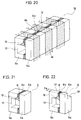
- Both of the cut faces are polished to produce a plurality of head cores 4 as shown in Fig. 21.
- a groove 18 is formed on the upper portion of head core 4.
- the width of a convex portion facing a medium 17, that is a track width T w is defined.
- head core 4 is attached in and fixed to a slit 20 of a slider 19 formed of nonmagnetic material with a glass layer 21.
- the outer form of slider 19 is worked to complete the floating type magnetic head.
- second thin film 6b is directly cut by a diamond grinding wheel rotating at a high speed.
- the adhesive strength of the second thin film 6b to the second substrate 5b is weak. Accordingly, the second thin film 6b may be completely separated or may be raised from the surface of the second substrate 5b as shown in Fig. 24.
- the manufacturing yield of magnetic heads decreases.
- the rise of second thin film 6b may cause false (secondary) gaps.
- the glass bonding shown in Fig. 19 is made by completely melting a glass rod inserted between a pair of core halves and flowing the melted glass into extra-processing grooves 13 and so forth. Accordingly, glass bonding temperature is higher than a softening point of glass by 150°C or more. As a result, the reaction proceeds at interfaces between the first and second substrates 5a and 5b, and first and second thin films 6a and 6b at the glass bonding process. Accordingly, there exists a problem that the false gaps are large.
- a method of manufacturing floating type magnetic heads according to the present invention includes the following steps.
- the step of forming a first groove includes forming an extra processing groove and an apex (gap depth regulating) groove.
- the step of forming the second groove includes forming a coil groove.
- the coil groove is formed adjacent the apex groove.
- the step of forming a glass layer inside the first groove includes steps of filling glass inside the apex groove and forming difference in level between the surface of the glass layer and the second gap forming surface inside the apex groove by partially removing the filled glass.
- the step of selectively forming the second thin film includes forming the second thin film on a sidewall surface of the apex groove.
- a coil groove as a second groove is formed in the exposed second gap forming surface adjacent the first groove.
- a glass layer is formed in advance inside the first groove. Accordingly, the second thin film is not cut due to formation of the second groove, which prevents it from being separated and raised from the second gap forming surface.
- a glass layer is formed in advance inside the first groove. Accordingly, the glass bonding of the first and second magnetic core half members is made by melting and solidifying the glass layer formed inside the first groove. The glass bonding between the first and second magnetic core half members can be made at relatively low temperature.
- a second thin film is formed on a sidewall surface of the apex groove. Accordingly, the magentic flux flow is facilitated in the ferromagnetic metal thin film in a completed magnetic head.
- Figs. 1, 2, 3, 4, 5, 6, 7, 8, 9, 10, 11, 12 and 13 are perspective views and sectional views sequentially showing structure according to respective manufacturing steps in the method of manufacturing a floating type magnetic head by one embodiment of the present invention.
- Figs. 14 and 15 are perspective views showing external appearance of a head core of a conventional floating type magnetic head.
- Figs. 16, 17, 18, 19, 20, 21, 22 and 23 are perspective views and sectional views sequentially showing structure according to respective manufacturing steps in a conventional method of manufacturing a floating type magmatic head.
- Fig. 24 is a partial sectional view showing a condition in which a thin film is raised from a substrate in the conventional process of manufacturing a floating type magnetic head.
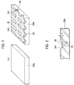
- a first substrate 22a and a second substrate 22b formed of Mn-Zn ferrite are prepared. Specular polishing is applied to upper and lower surfaces of first substrate 22a and a lower surface of second substrate 22b. Subsequently, extra processing grooves 23 and apex grooves 24 having oblique surfaces 241 are formed on the upper surface as a gap forming surface of the second substrate 22b to be a C type core half. First glass 25 is filled in extra processing grooves 23 and apex grooves 24. Specular polishing is applied to the upper surface of the second substrate 22b. In the embodiment, the first glass 25 is provided by holding glass having a softening point of 590°C at 690°C for 40 minutes.
- etching processing is applied to the upper surface of the second substrate 22b. Upper portion of the glass 25 filled in extra processing grooves 23 and apex grooves 24 is thus removed.
- the difference in level l is provided.
- the etching process is performed using a HF (HydroFluoric acid) acqueous solution of concentration of 1%.
- the difference in level l of 10 ⁇ m is thus formed. If the difference l is too large, glass is not filled sufficiently to corners of lower ends of gaps in the later glass bonding process. If the difference l is too small, the mask alignment is difficult in patterning a ferromagnetic metal thin film in the later step.
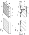
- a first thin film 30a is formed by sputtering all over the upper surface of first substrate 22a.
- the first thin film 30a is formed of an underlying layer 26 such as SiO2 or the like, a ferromagnetic metal thin film 27 such as Sendust or the like, a gap spacer 28 such as SiO2 or the like and second glass 29 for gap bonding.
- a second thin film 30b is formed all over the upper surface of second substrate 22b by Sputtering.
- the second thin film 30b is formed of an underlying layer 31 such as SiO2 or the like, a ferromagnetic metal thin film 32 such as Sendust or the like and a gap spacer 33 such as SiO2 or the like.
- the softening point of the second glass 29 is 640°C.
- the film of second glass 29 has a thickness of 500 ⁇ , which is formed by the RF magnetron type sputter method.
- the film thickness of underlying layers 26, 31 is 50 ⁇
- the film thickness of ferromagnetic metal thin films 27, 32 is 2.5 ⁇ m
- the film thickness of gap spacers 28, 33 is 0.25 ⁇ m.
- first thin film 30a and second thin film 30b are patterned.
- the patterning of second thin film 30b is performed by removing by ionmilling or the like second thin film 30b provided on a portion in which first glass 25 is filled and a portion at which coil grooves are to be formed.
- the patterning of first thin film 30a is performed by removing by ionmilling or the like corresponding portions similarly to the patterning of second thin film 30b.
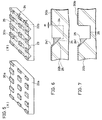
- Fig. 6 is a partial section view showing a condition in which the ionmilling process is applied to second substrate 22b.
- a coil groove 35 is formed at a portion designated by a broken line 34 distant from an end portion of second thin film 30b by the distance m. Coil groove 35 is thus formed as shown in Fig. 7.
- the distance m is set 30 ⁇ m so that a cutting wheel for coil groove work does not contact with the thin film.
- first and second substrates 22a and 22b are abutted against each other so that the first and second thin films 30a and 30b face to each other.
- first glass 25 and second glass 29 (not shown in Fig. 8 but shown in Fig. 4) are melted and solidified to bond the first and second substrates 22a and 22b.
- a block 36 is thus formed.
- the glass bonding is made by holding it at a peak temperature of 700°C for 10 minutes.
- Fig. 9 is a main portion section view showing the block 36 after glass bonding.
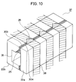
- block 36 is cut off along the broken lines B - B' shown in Fig. 8.
- a core block 37 is thus formed as shown in Fig. 10.
- the external appearance of core block 37 is worked and formed to desired dimensions.
- a plurality of head cores 39 as shown in Fig. 11 are produced.
- Both sides of head core 39 are polished. Subsequently, as shown in Fig. 12, similarly to the conventional example, a groove 41 is formed on an upper portion of head core 39.
- the groove 41 defines the width of convex portion facing to medium 40, that is, the track width T w on the upper portion of head core 39.
- head core 39 is provided and fixed with third glass 21 in a slit 20 of a slider 19 formed of nonmagnetic material. Subsequently, the outer shape of slider 19 is worked to complete a floating type magnetic head.
- a coil groove 35 is formed at a portion distant from an end portion of the remaining second thin film 30b by the distance m. Accordingly, a cutting wheel for working grooves does not contact with second thin film 30b. Furthermore, coil groove 35 is formed adjacent to apex groove 24. First glass 25 is formed in apex groove 24. Thus, in the process of forming coil grooves, a diamond grinding wheel rotating at a high speed does not directly cut second thin film 30b. As a result, separation and rise of second thin film 30b are prevented.
- the first and second substrates 22a and 22b are bonded with glass by melting and solidifying first glass 25 previously filled in the groove. Accordingly, as compared to the conventional method in which glass rods are inserted and melted, the melting and bonding temperature can be decreased. Reaction at the interfaces between the first and second substrates 22a, 22b and ferromagnetic metal thin films 27, 32 in the first and second thin films 30a and 30b can be thus suppressed. As a result, an increase of false gaps can be restrained in a completed magnetic head.
Landscapes
- Engineering & Computer Science (AREA)
- Manufacturing & Machinery (AREA)
- Magnetic Heads (AREA)
Applications Claiming Priority (2)
| Application Number | Priority Date | Filing Date | Title |
|---|---|---|---|
| JP2231676A JP2567725B2 (ja) | 1990-08-31 | 1990-08-31 | 浮動型磁気ヘッドの製造方法 |
| JP231676/90 | 1990-08-31 |
Publications (3)
| Publication Number | Publication Date |
|---|---|
| EP0473092A2 true EP0473092A2 (fr) | 1992-03-04 |
| EP0473092A3 EP0473092A3 (en) | 1992-04-01 |
| EP0473092B1 EP0473092B1 (fr) | 1996-05-01 |
Family
ID=16927241
Family Applications (1)
| Application Number | Title | Priority Date | Filing Date |
|---|---|---|---|
| EP91114263A Expired - Lifetime EP0473092B1 (fr) | 1990-08-31 | 1991-08-26 | Méthode de fabrication d'une tête magnétique de type flottante |
Country Status (4)
| Country | Link |
|---|---|
| US (1) | US5146671A (fr) |
| EP (1) | EP0473092B1 (fr) |
| JP (1) | JP2567725B2 (fr) |
| DE (1) | DE69119163T2 (fr) |
Families Citing this family (4)
| Publication number | Priority date | Publication date | Assignee | Title |
|---|---|---|---|---|
| US5828506A (en) * | 1996-08-08 | 1998-10-27 | Eastman Kodak Company | Magnetic head interface having a single narrow band of contact for longitudinal edge track record/reproduce on magnetics-on-film (MOF) |
| JP3790347B2 (ja) * | 1997-11-26 | 2006-06-28 | Tdk株式会社 | 薄膜磁気ヘッドの製造方法 |
| JP3415432B2 (ja) * | 1998-03-31 | 2003-06-09 | ティーディーケイ株式会社 | 薄膜磁気ヘッドおよびその製造方法 |
| US6635941B2 (en) * | 2001-03-21 | 2003-10-21 | Canon Kabushiki Kaisha | Structure of semiconductor device with improved reliability |
Citations (3)
| Publication number | Priority date | Publication date | Assignee | Title |
|---|---|---|---|---|
| JPS62246110A (ja) * | 1986-04-18 | 1987-10-27 | Victor Co Of Japan Ltd | 複合型磁気ヘツドとその製造方法 |
| EP0328104A2 (fr) * | 1988-02-09 | 1989-08-16 | Sanyo Electric Co., Ltd. | Tête magnétique et son procédé de fabrication |
| US4890378A (en) * | 1985-08-28 | 1990-01-02 | Canon Kabushiki Kaisha | Method for manufacturing a magnetic head core having a magnetic film |
Family Cites Families (3)
| Publication number | Priority date | Publication date | Assignee | Title |
|---|---|---|---|---|
| JPS60205808A (ja) * | 1984-03-29 | 1985-10-17 | Sony Corp | 磁気ヘツド |
| JPS62295207A (ja) * | 1986-06-13 | 1987-12-22 | Hitachi Metals Ltd | 磁気デイスク用浮上型磁気ヘツド |
| JPH0778853B2 (ja) * | 1988-05-06 | 1995-08-23 | 三洋電機株式会社 | 浮動型磁気ヘツド及びその製造方法 |
-
1990
- 1990-08-31 JP JP2231676A patent/JP2567725B2/ja not_active Expired - Lifetime
-
1991
- 1991-08-26 EP EP91114263A patent/EP0473092B1/fr not_active Expired - Lifetime
- 1991-08-26 DE DE69119163T patent/DE69119163T2/de not_active Expired - Fee Related
- 1991-08-30 US US07/753,157 patent/US5146671A/en not_active Expired - Lifetime
Patent Citations (3)
| Publication number | Priority date | Publication date | Assignee | Title |
|---|---|---|---|---|
| US4890378A (en) * | 1985-08-28 | 1990-01-02 | Canon Kabushiki Kaisha | Method for manufacturing a magnetic head core having a magnetic film |
| JPS62246110A (ja) * | 1986-04-18 | 1987-10-27 | Victor Co Of Japan Ltd | 複合型磁気ヘツドとその製造方法 |
| EP0328104A2 (fr) * | 1988-02-09 | 1989-08-16 | Sanyo Electric Co., Ltd. | Tête magnétique et son procédé de fabrication |
Non-Patent Citations (1)
| Title |
|---|
| PATENT ABSTRACTS OF JAPAN vol. 12, no. 119 (P-689)(2966) 14 April 1988 & JP-A-62 246 110 ( VICTOR CO OF JAPAN LTD ) 27 October 1987 * |
Also Published As
| Publication number | Publication date |
|---|---|
| DE69119163D1 (de) | 1996-06-05 |
| JP2567725B2 (ja) | 1996-12-25 |
| EP0473092A3 (en) | 1992-04-01 |
| US5146671A (en) | 1992-09-15 |
| EP0473092B1 (fr) | 1996-05-01 |
| DE69119163T2 (de) | 1996-12-05 |
| JPH04113506A (ja) | 1992-04-15 |
Similar Documents
| Publication | Publication Date | Title |
|---|---|---|
| EP0125891B1 (fr) | Tête magnétique de type composé et son procédé de fabrication | |
| EP0115842B1 (fr) | Tête magnétique et procédé pour fabriquer celle-ci | |
| KR920006124B1 (ko) | 자기헤드 및 그 제조방법 | |
| US4755899A (en) | Magnetic transducer head having an alloy thin film of high saturation magnetic flux density slantly provided with respect to an operating magnetic gap formed therein | |
| JPH0345442B2 (fr) | ||
| EP0473092B1 (fr) | Méthode de fabrication d'une tête magnétique de type flottante | |
| JPH0554167B2 (fr) | ||
| US5016341A (en) | A process for producing magnetic heads of the floating type | |
| JP2669965B2 (ja) | 磁気ヘッドの製造方法 | |
| JP2596070B2 (ja) | 磁気ヘッドの製造方法 | |
| JPH02247816A (ja) | 固定磁気ディスク装置用コアスライダの製造法 | |
| JP3104185B2 (ja) | 磁気ヘッド | |
| JPS63164010A (ja) | 磁気ヘツドの製造方法 | |
| JP2562752B2 (ja) | 磁気ヘッドコアの製法 | |
| JP2810820B2 (ja) | 磁気ヘッド及び磁気ヘッドの製造方法 | |
| JPH0648529B2 (ja) | 磁気ヘツド | |
| JPH0585962B2 (fr) | ||
| JPH0833980B2 (ja) | 磁気ヘッドの製造方法 | |
| JPH02132612A (ja) | 磁気ヘッドの製造方法 | |
| JPS62139110A (ja) | 磁気ヘツドの製造方法 | |
| JPS63108510A (ja) | 磁気ヘツド | |
| JPH0363906A (ja) | 磁気ヘッドの製造方法 | |
| JPH0371402A (ja) | 磁気ヘッドの製造方法 | |
| JPS63288407A (ja) | 磁気ヘツドの製造方法 | |
| JPS618710A (ja) | 磁気ヘツドの製造方法 |
Legal Events
| Date | Code | Title | Description |
|---|---|---|---|
| PUAI | Public reference made under article 153(3) epc to a published international application that has entered the european phase |
Free format text: ORIGINAL CODE: 0009012 |
|
| PUAL | Search report despatched |
Free format text: ORIGINAL CODE: 0009013 |
|
| AK | Designated contracting states |
Kind code of ref document: A2 Designated state(s): DE FR GB |
|
| AK | Designated contracting states |
Kind code of ref document: A3 Designated state(s): DE FR GB |
|
| 17P | Request for examination filed |
Effective date: 19920507 |
|
| 17Q | First examination report despatched |
Effective date: 19930325 |
|
| GRAH | Despatch of communication of intention to grant a patent |
Free format text: ORIGINAL CODE: EPIDOS IGRA |
|
| GRAA | (expected) grant |
Free format text: ORIGINAL CODE: 0009210 |
|
| AK | Designated contracting states |
Kind code of ref document: B1 Designated state(s): DE FR GB |
|
| ET | Fr: translation filed | ||
| REF | Corresponds to: |
Ref document number: 69119163 Country of ref document: DE Date of ref document: 19960605 |
|
| PLBE | No opposition filed within time limit |
Free format text: ORIGINAL CODE: 0009261 |
|
| STAA | Information on the status of an ep patent application or granted ep patent |
Free format text: STATUS: NO OPPOSITION FILED WITHIN TIME LIMIT |
|
| 26N | No opposition filed | ||
| REG | Reference to a national code |
Ref country code: GB Ref legal event code: IF02 |
|
| PGFP | Annual fee paid to national office [announced via postgrant information from national office to epo] |
Ref country code: FR Payment date: 20020808 Year of fee payment: 12 |
|
| PGFP | Annual fee paid to national office [announced via postgrant information from national office to epo] |
Ref country code: GB Payment date: 20020821 Year of fee payment: 12 |
|
| PGFP | Annual fee paid to national office [announced via postgrant information from national office to epo] |
Ref country code: DE Payment date: 20020904 Year of fee payment: 12 |
|
| PG25 | Lapsed in a contracting state [announced via postgrant information from national office to epo] |
Ref country code: GB Free format text: LAPSE BECAUSE OF NON-PAYMENT OF DUE FEES Effective date: 20030826 |
|
| PG25 | Lapsed in a contracting state [announced via postgrant information from national office to epo] |
Ref country code: DE Free format text: LAPSE BECAUSE OF NON-PAYMENT OF DUE FEES Effective date: 20040302 |
|
| GBPC | Gb: european patent ceased through non-payment of renewal fee | ||
| PG25 | Lapsed in a contracting state [announced via postgrant information from national office to epo] |
Ref country code: FR Free format text: LAPSE BECAUSE OF NON-PAYMENT OF DUE FEES Effective date: 20040430 |
|
| REG | Reference to a national code |
Ref country code: FR Ref legal event code: ST |