EP0472289B1 - Anordnung zur Zustandsumschaltung für Lautfernsprechgerät - Google Patents
Anordnung zur Zustandsumschaltung für Lautfernsprechgerät Download PDFInfo
- Publication number
- EP0472289B1 EP0472289B1 EP91306639A EP91306639A EP0472289B1 EP 0472289 B1 EP0472289 B1 EP 0472289B1 EP 91306639 A EP91306639 A EP 91306639A EP 91306639 A EP91306639 A EP 91306639A EP 0472289 B1 EP0472289 B1 EP 0472289B1
- Authority
- EP
- European Patent Office
- Prior art keywords
- signals
- alerting
- speakerphone
- loudspeaker
- state
- Prior art date
- Legal status (The legal status is an assumption and is not a legal conclusion. Google has not performed a legal analysis and makes no representation as to the accuracy of the status listed.)
- Expired - Lifetime
Links
- 238000006243 chemical reaction Methods 0.000 claims description 15
- 230000002238 attenuated effect Effects 0.000 claims description 7
- 230000007246 mechanism Effects 0.000 description 7
- 238000010586 diagram Methods 0.000 description 6
- 230000005236 sound signal Effects 0.000 description 5
- 238000012986 modification Methods 0.000 description 4
- 230000004048 modification Effects 0.000 description 4
- 230000000694 effects Effects 0.000 description 2
- 230000001154 acute effect Effects 0.000 description 1
- 230000003321 amplification Effects 0.000 description 1
- 230000008859 change Effects 0.000 description 1
- 238000001514 detection method Methods 0.000 description 1
- 238000012544 monitoring process Methods 0.000 description 1
- 238000003199 nucleic acid amplification method Methods 0.000 description 1
- 230000024977 response to activity Effects 0.000 description 1
- 230000011664 signaling Effects 0.000 description 1
- 230000007704 transition Effects 0.000 description 1
- 230000000007 visual effect Effects 0.000 description 1
Images
Classifications
-
- H—ELECTRICITY
- H04—ELECTRIC COMMUNICATION TECHNIQUE
- H04M—TELEPHONIC COMMUNICATION
- H04M9/00—Arrangements for interconnection not involving centralised switching
- H04M9/08—Two-way loud-speaking telephone systems with means for conditioning the signal, e.g. for suppressing echoes for one or both directions of traffic
-
- H—ELECTRICITY
- H04—ELECTRIC COMMUNICATION TECHNIQUE
- H04M—TELEPHONIC COMMUNICATION
- H04M19/00—Current supply arrangements for telephone systems
- H04M19/02—Current supply arrangements for telephone systems providing ringing current or supervisory tones, e.g. dialling tone or busy tone
-
- H—ELECTRICITY
- H04—ELECTRIC COMMUNICATION TECHNIQUE
- H04M—TELEPHONIC COMMUNICATION
- H04M19/00—Current supply arrangements for telephone systems
- H04M19/02—Current supply arrangements for telephone systems providing ringing current or supervisory tones, e.g. dialling tone or busy tone
- H04M19/04—Current supply arrangements for telephone systems providing ringing current or supervisory tones, e.g. dialling tone or busy tone the ringing-current being generated at the substations
Definitions
- This invention relates to telecommunications station sets.
- the prior art has used various audible signals, ringers, buzzers, etc., as well as visual signals such as light bulbs, to alert a party of the arrival of an incoming call to the party's telephone station set.
- the audible alerting tones that are produced at the telephone station set to signal an incoming call are typically constant in volume regardless of the busy/idle state of the telephone. Therefore, if the called party is already off-hook and engaged in an existing call, the audible alerting signal of a second incoming call may be very disturbing and irritating, and especially so if the existing call is on a speakerphone.
- speakerphones generally permit only one-way communications, i.e., switching between transmit and receive depending on which party is presently speaking, or is the loudest if both started speaking simultaneously, an incoming alerting signal may not only disturb and annoy the two parties but may also disrupt communications between the two parties.
- the prior art also has taught the use of the speakerphone of a telephone station set to generate audible alerting signals.
- the set When the set is on-hook, it responds to receipt of notification of an incoming call (e.g., a ringing signal on the telephone line) by connecting an alerting signal generator to the loudspeaker of the speakerphone and driving the loudspeaker with output of the alerting signal generator to produce the audible alerting tone.
- the alerting signal generator is not used to produce an audible alerting tone.
- the loudspeaker and the microphone are located in close proximity to each other, very much closer than is typically the case between a conventional telephone station set ringer and a microphone of the station set when the set is off-hook. Consequently, the speakerphone loudspeaker-generated alerting signals more readily and more strongly affect the speakerphone microphone and cause more interference, annoyance, and disruption thereby, than would typically be true of non-speakerphone generated alerting signals.
- a telecommunications station set such as a telephone station set, generates outgoing signals and receives incoming signals, and includes an arrangement for generating audible alerting signals both when the set is on-hook and when it is off-hook and whose volume depends on the activity states of lines that carry the outgoing and incoming signals.
- the arrangement includes means for generating audible alerting signals, and means for controlling the volume of the audible alerting signals as a function of the strengths of the outgoing and the incoming signals.
- the telecommunication station set uses the same arrangement to produce audible alerting signals (e.g., ringing signals) both while it is on-hook and while it is off-hook, and controls the volume of the produced audible alerting signals in accordance with speakerphone control states.
- the set includes a speakerphone loudspeaker or some other means for converting received alerting signals (e.g., ringing signals) into audible alerting signals.
- the set also includes an arrangement that responds to communications signals received by the station set by generating a plurality of speakerphone control state signals, e.g., signals indicative of individual ones of speakerphone idle, listening, and talking states.
- this arrangement is the speakerphone control circuit itself.
- the set further includes an alert-signal generating arrangement that supplies the alerting signals to the loudspeaker or other signal conversion means, while the station set is on-hook and also while the station set is off-hook, for conversion into audible alerting signals.
- the alert-signal generating arrangement is responsive to the speakerphone control state signal generating arrangement: when the latter generates a first control state signal, representative of, e.g., a speakerphone talking state, the former supplies alerting signals convertible into first audible alerting signals having a volume, e.g., a normal or loud volume; when the latter generates a second control state signal, representative of, e.g., a speakerphone listening state, the former supplies alerting signals convertible into second audible alerting signals having a volume different from the volume of the first audible alerting signals, e.g., an attenuated or low volume.
- the invention is especially suited for implementation in a station set that includes a speakerphone with a loudspeaker, and consequently already also includes a speakerphone control circuit having a plurality of control states for controlling operation of the speakerphone.
- the station set includes an arrangement for generating alerting signals and supplying the alerting signals to the loudspeaker, while the station set is on hook and also while the station set is off-hook, for conversion into audible alerting signals (e.g., ringing). If the control circuit is in a first control state (illustratively, talking), the arrangement supplies to the loudspeaker first alerting signals for conversion thereby into first audible signals having a volume, illustratively a "normal" volume.
- control circuit If the control circuit is in a second control state (illustratively, listening), the arrangement supplies to the loudspeaker second alerting signals for conversion thereby into second audible alerting signals having a volume different from (illustratively lower than) the volume of the first audible alerting signals. Further illustratively, if the control circuit is in a third control state (illustratively, idle), it makes a transition to the first control state to supply alerting signals to the loudspeaker.
- a third control state illustratedratively, idle
- the invention uses a single arrangement for producing alerting signals both when the station set is on-hook and off-hook. It thus eliminates the need for two separate arrangements, one for when the set is on-hook and the other for when the set is off-hook.
- the arrangement preferably uses the speakerphone loudspeaker to generate audible alerting signals, and thereby avoids the need for a separate source of audible alerting signals, such as a ringer.
- the arrangement generates the alerting signals in the station set, and thereby frees apparatus that is connected to the station set over a telephone line from having to generate signals directly convertible by the loudspeaker into audible alerting signals.
- the arrangement avoids the disadvantages associated with constant-volume audible-alerting signaling, and ensures that the audible alerting signals are not disturbing or irritating to either party to an ongoing call and do not disrupt the ongoing call.
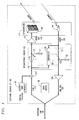
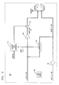
- FIG. 1 shows a telephone station set 100, which is a conventional set but for modifications described herein.
- set 100 includes a hookswitch 108, a conventional remote speakerphone 101, and a conventional speakerphone circuit 102 for controlling the operation of speakerphone 101.
- Speakerphone 101 includes a loudspeaker 140 and a microphone 141. The input of loudspeaker 140 and the output of microphone 141 are connected to speakerphone circuit 102 by an AUDIO OUT line 118 and an AUDIO IN line 128, respectively.
- Speakerphone circuit 102 connects lines 118 and 128 to LINE IN line 119 and LINE OUT line 129, respectively. Lines 119 and 129 are in turn connected, through conventional circuitry of set 100 (not shown) to a telephone line 106.
- Audio e.g., voice
- signals incoming on telephone line 106 appear on LINE IN line 119, and audio signals outgoing on telephone line 106 are supplied thereto by LINE OUT line 129.
- An output of speakerphone circuit 102 is connected to LINE OUT line 129 through a conventional amplifier 104.
- a second output of speakerphone circuit 102 is connected to AUDIO OUT line 118 through a conventional amplifier 103.
- Amplifiers 103 and 104 merely boost the signal strength of signals incoming thereto and transmit the boosted signals at their outputs.
- Circuit 110 is illustratively a conventional voltage-divider circuit that has a first resistor 113 in line with the input of amplifier 103, and a second resistor 111 that is selectively switched between ground and the signal path between LINE IN line 119 and amplifier 103 by a switch 112. Operation of switch 112 is controlled by controller 130 of speakerphone circuit 102.
- AUDIO IN line 128 is connected to the input of amplifier 104 through a switched attenuator circuit 120 of speakerphone circuit 102.
- Circuit 120 duplicates circuit 110 and includes a first resistor 123 in line with the input of amplifier 104, and a second resistor 121 that is selectively switched between ground and the signal path between AUDIO IN line 128 and amplifier 104 by a switch 122. Operation of switch 122 is also controlled by controller 130.
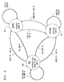
- Controller 130 exerts control on circuits 110 and 120 in response to activity that it senses on LINE IN line 119 and AUDIO IN line 128, in a manner that illustratively creates three operational states for circuit 102. This is illustrated in FIG.2.
- controller 130 sets circuit 102 into idle state 200, wherein both resistors 111 and 121 are switched into their respective signal paths.
- controller 130 senses presence of input signals, it causes circuit 102 to leave idle state 200 and to assume one of listening state 201 and talking state 202, depending upon the relative strength --volume-- of the line in and audio in signals. If the audio in signals are stronger than the line in signals, controller 130 causes circuit 102 to assume listening state 201, wherein resistor 111 is switched into its signal path to attenuate the line in signals input to loudspeaker 140.
- controller 130 causes circuit 102 to assume talking state 202, wherein attenuator 121 is switched into its signal path to attenuate the output of microphone 141 to LINE OUT line 129.
- controller 130 will keep circuit 102 in state 201 for as long as audio in signals are present, and will return circuit 102 to idle state 200 upon detecting absence of the audio in signals.
- talking state 202 was assumed by circuit 102
- controller 130 will keep circuit 102 in state 202 for as long as line in signals are present, and will return circuit 102 to idle state 200 upon detecting absence of the line in signal.
- idle state 200 the above-described check of the relative strengths of the audio in and line in signals is then repeated.
- controller 130 may switch between talking state 202 and listening state 201 as the relative signal strengths of the audio in and the line in signals change, and for idle state 200 to be resumed only when controller 130 ceases to sense any input signals.
- This alternative is shown by dashed lines in FIG. 2. It is not a favored alternative from a human factors standpoint.
- telephone station set 100 and its operation are conventional.
- telephone station set 100 would also include an alerting tone generator, e.g., ringing tone generator, operable when set 100 is on-hook and connected directly to the input of loudspeaker 140 for driving loudspeaker 140 with alerting signals that cause loudspeaker 140 to produce audible alerting signals having a constant volume.
- set 100 includes an alerting tone generator 105 whose output is connected to the input of loudspeaker 140 through switched attenuator circuit 110.
- the alerting signals that reach and drive loudspeaker 140 are controlled by the present state of speakerphone circuit 102. This causes loudspeaker 140 to produce audible alerting signals that vary in volume with the present state of speakerphone circuit 102.
- Alerting tone generator 105 is activated to produce alerting signals, and is deactivated, in a conventional manner, via a CONTROL signal supplied thereto by conventional circuitry of set 100.
- Generator 105 is also conventional, and produces at its output constant-volume alerting signals.
- the output of generator 105 is combined with the audio in signals from AUDIO IN line 119 by a conventional summing circuit 107, and the combined signals are supplied from the output of circuit 107 to the input of switched attenuator circuit 110 and the line-monitoring input of controller 130.
- the alerting operation of the above-described circuitry of set 100 is as follows.
- set 100 When set 100 is on-hook, no audio signals are present and speakerphone circuit 102 is in idle state 200.
- generator 105 is caused to generate and output alerting signals.
- the alerting signals pass through summing circuit 107 to speakerphone circuit 102. They are detected by controller 130, which responds by sending circuit 102 into talking state 202. Consequently, the alerting signals pass unattenuated through circuit 110 of speakerphone circuit 102 to amplifier 103, are amplified thereby, and then pass through AUDIO OUT line 118 to the input of loudspeaker 140. Being amplified and unattenuated alerting signals, they cause loudspeaker 140 to produce loud audible alerting signals.
- generator 105 When set 100 receives notice of abandonment of the incoming call before set 100 goes off-hook, or when set 100 goes off-hook, generator 105 is caused to cease producing alerting signals, the audible alerting signals produced by loudspeaker 140 stop, and speakerphone circuit 102 returns to idle state 200. If set 100 has gone off-hook, the call proceeds conventionally.
- speakerphone circuit 102 When set 100 is off-hook, e.g., a call is in progress, speakerphone circuit 102 is typically either in talking state 202 or listening state 201, depending upon whether the calling or the called party is talking, or talking the loudest. If set 100 receives notice of a second incoming call, e.g., as part of a call-waiting service, it again causes generator 105 to generate the alerting signals. The alerting signals are summed by circuit 107 with any voice signals incoming on LINE IN line 119. The combined signals pass through circuit 110 of speakerphone circuit 102 to amplifier 103, are amplified thereby, and then are passed to loudspeaker 140.
- speakerphone circuit 102 momentarily happens to be in idle state 200 at that instant, detection of the incoming signals by controller 130 sends speakerphone circuit 102 into talking state 202. If speakerphone circuit 102 is in listening state 201 or talking state 202, the appearance of the alerting signals in conjunction with otherwise-present audio signals has no effect on the state of speakerphone circuit 102 in the typical case described above in conjunction with FIG. 2. But in the alternative case there described, appearance of the alerting signals will cause circuit 102 to remain in talking state 202, or to switch from listening state 201 to talking state 202, depending on the present state.
- Alerting signals reaching loudspeaker 140 while circuit 102 is in talking state 202 are amplified and unattenuated.
- loudspeaker 140 produces loud audible alerting signals. This ensures that the user of set 100 is able to hear the audible alerting signals above the other incoming audio signals, e.g., voice signals, to which he or she is listening.
- the output of microphone 141 is attenuated by circuit 120 in talking state 202.
- the audible alerting signals are picked up by microphone 141, they are attenuated by circuit 120 so as not to cause call disruption and annoying feedback to the other, remote, party to the call.
- loudspeaker 140 produces quiet audible alerting signals. This is desirable for two reasons. Firstly, loudspeaker 140 is quiescent in listening state 201, so loud audible alerting signals would be startling and annoying to the speakerphone user. Nor are loud audible alerting signals needed in order to be heard above other audible signals reproduced by loudspeaker 140. Secondly, the quiet audible alerting signals ensure that they are not picked up at all, or are picked up only very faintly, by microphone 141, so as not to cause call disruption and annoying feedback to the remote party to the call.
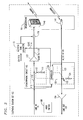
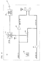
- FIG. 3 shows an alternative embodiment of the speakerphone state-controlled alerting arrangement.
- telephone station set 100 includes an alerting tone generator 115 that produces variable-strength alerting signals, and hence its output signals strength need not be controlled by switched attenuator circuit 110 of speakerphone circuit 102. Rather, the output of circuit 110 and the output of generator 115 are summed by a summing circuit 116 and the combined signals are applied thereby to the input of loudspeaker 140.
- Controller 130 of speakerphone circuit 102 has a state output connected by a STATE signal line 114 to a signal-strength control input of generator 115. Controller 130 generates on line 114 signals indicative of the present state of speakerphone circuit 102.
- Generator 115 receives these signals and responds to them by varying the strength of the alerting signals which it generates. Specifically, controller 130 keeps line 114 deasserted when circuit 102 is in idle state 200 and talking state 202, and asserts line 114 when circuit 102 is in listening state 201. Generator 115 generates full-strength alerting signals when line 114 is deasserted, and generates "attenuated", low-strength, alerting signals when line 114 is asserted.
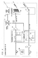
- FIG. 4 duplicates FIG. 3 with the exception that the output of generator 115 is not input to loudspeaker 140, but rather is input to, and drives, a separate audible alert producer 200, such as a ringer or a separate loudspeaker. Consequently, set 100 of FIG. 4 continues to use the same alerting mechanism while it is on-hook and off-hook, and the volume of the audible alerting signals continues to be controlled by the state of speakerphone circuit 102.
- FIG. 3 may be applied to an alternative embodiment of a set 100 that does not include a speakerphone, as shown in FIGS. 5 and 6.
- FIG. 5 shows a station set 100 that has no speakerphone, but has a headset 500 in place of a speakerphone. Consequently, a speakerphone circuit 102 is not required, and is absent.
- set 100 of FIG. 5 does retain a portion of the functionality of speakerphone circuit 102, namely the relative audio signal level-sensing function of controller 130 of FIG. 3.
- FIG. 5 retains controller 130 of FIG. 3 and merely eliminates attenuators 110 and 120 of speakerphone circuit 102 of FIG. 4, for the purpose of controlling the output of alerting tone generator 115 as a function of speakerphone circuit states.
- the alerting tones generated by generator 115 are combined with the audio out signals on AUDIO OUT line 118 by an adder 116, as in FIG. 3, but the output of adder 116 is fed into headset 500 to produce audible signals.
- a handset can be substituted for, or used in conjunction with headset 500.
- FIG. 6 duplicates FIG. 5 with the exception that headset 500 is replaced by a handset 600 and a separate audible alert producer 200 is included in station set 100 of FIG. 6, as in FIG. 4. Consequently, the output of alerting tone generator 115 is not combined with audio out signals, but is fed to the input of producer 200, as in FIG. 4. Like set 100 of FIG. 5, set 100 of FIG. 6 continues to use the same alerting mechanism while it is on-hook and off-hook, and the volume of the audible alerting signals continues to be controlled by speakerphone circuit states.
- a headset may be substituted for, or used in conjunction with handset 600.
- the terminal station set may be either an analog or a digital set.
- the terminal station set need not be a telephone station set, but may be a part of any telecommunications system.
- 3 basic speakerphone states have been illustrated, there may be more than 3 states, each representing a different level of attenuation and/or amplification.
Landscapes
- Engineering & Computer Science (AREA)
- Signal Processing (AREA)
- Telephone Function (AREA)
- Interconnected Communication Systems, Intercoms, And Interphones (AREA)
Claims (12)
- Sprechstellenapparat (100) mit ersten Mitteln (140) zum Umwandeln von empfangenen Warnsignalen in hörbare Warnsignale und auf von dem Sprechstellenapparat empfangene Kommunikationssignale reagierenden zweiten Mitteln (130) zur Erzeugung einer Mehrzahl von Lautfernsprecher-Steuerzustandssignalen, gekennzeichnet durch mit den ersten und zweiten Mitteln verbundene dritte Mittel (110, 105; 115) zur Zuführung der Warnsignale zu den ersten Mitteln, während der Sprechstellenapparat aufgelegt ist, und auch zur Umwandlung in hörbare Warnsignale, während der Sprechstellenapparat ausgehängt ist, wobei die dritten Mittel auf die Erzeugung eines ersten Steuerungszustandssignals durch die zweiten Mittel reagieren, um den ersten Mitteln erste Warnsignale zur Umwandlung in erste hörbare Warnsignale mit einer Lautstärke zuzuführen, und auf die Erzeugung eines zweiten Steuerungszustandssignals durch die zweiten Mittel reagieren, um den ersten Mitteln zweite Warnsignale zur Umwandlung in zweite hörbare Warnsignale mit einer sich von der Lautstärke der ersten hörbaren Warnsignale unterscheidenden Lautstärke zuzuführen.
- Sprechstellenapparat nach Anspruch 1, wobei die dritten Mittel einen Signalgenerator (115) zur Erzeugung einer Mehrzahl von verschiedenen Warnsignalen umfassen und auf die Erzeugung des ersten Zustandssignals durch die zweiten Mittel reagieren, um die ersten Warnsignale zu erzeugen, und auf die Erzeugung des zweiten Zustandssignals durch die zweiten Mittel reagieren, um die zweiten Warnsignale zu erzeugen.
- Sprechstellenapparat nach Anspruch 1 oder 2, wobei die zweiten Mittel eine Lautfernsprecher-Steuerschaltung (130) mit einer Mehrzahl von Steuerungszuständen zur Steuerung der Funktion eines Lautfernsprechers umfassen.
- Sprechstellenapparat nach Anspruch 3, wobei die ersten Mittel einen durch die Lautfernsprecher-Steuerschaltung gesteuerten Lautfernsprecher umfassen, der einen Lautsprecher (140) zur Umwandlung von empfangene Warnsignale umfassenden Empfangssignalen in hörbare Signale umfaßt.
- Sprechstellenapparat nach Anspruch 1 oder 2, wobei die zweiten Mittel sowohl auf von dem Sprechstellenapparat von einer externen Fernmeldeleitung (119) empfangene Kommunikationssignale als auch auf von einem Benutzer des Apparats empfangene Kommunikationssignale reagierende Mittel (130) zur Erzeugung einzelner eines (a) ersten einen ersten Zustand zur Dämpfung einer Ausgabe eines Lautfernsprechermikrophons darstellenden Signals und (b) eines zweiten einen zweiten Zustand zur Dämpfung einer Eingabe in einen Lautfernsprecherlautsprecher darstellenden Signals umfassen.
- Sprechstellenapparat nach Anspruch 5, wobei der Apparat keinen durch die zweiten Mittel gesteuerten Lautfernsprecher aufweist.
- Sprechstellenapparat nach Anspruch 6, wobei die ersten Mittel schallerzeugende Mittel (200) zur gezielten Umwandlung von empfangenen Warnsignalen in hörbare Warnsignale umfassen.
- Sprechstellenapparat nach Anspruch 6, wobei die ersten Mittel einen Kopfhörer (500) für den Benutzer des Apparats umfassen.
- Sprechstellenapparat nach Anspruch 1, wobei die ersten Mittel einen einen Lautsprecher (140) umfassenden Lautfernsprecher (101) umfassen, die zweiten Mittel eine mit dem Lautfernsprecher verbundene Lautfernsprecher-Steuerschaltung (130) umfassen, die eine Mehrzahl von Steuerungszuständen zur Steuerung der Funktion des Lautfernsprechers aufweist, und die dritten Mittel mit dem Lautsprecher und mit der Steuerschaltung verbundene Signalmittel (105, 110; 115) zur Erzeugung von Warnsignalen und Zuführung der Warnsignale zum Lautsprecher, während der Sprechstellenapparat aufgelegt ist und auch während der Sprechstellenapparat ausgehängt ist, zur Umwandlung in hörbare Warnsignale umfassen, wobei die Signalmittel darauf reagieren, daß sich die Steuerschaltung in einem ersten Steuerungszustand befindet, um dem Lautsprecher erste Warnsignale zur Umwandlung in erste hörbare Warnsignale mit einer Lautstärke zuzuführen, und darauf reagieren, daß sich die Steuerschaltung in einem zweiten Steuerungszustand befindet, um dem Lautsprecher zweite Warnsignale zur Umwandlung in zweite hörbare Warnsignale mit einer Lautstärke, die sich von der Lautstärke der ersten hörbaren Warnsignale unterscheidet, zuzuführen.
- Sprechstellenapparat nach Anspruch 9, wobei die Signalmittel folgendes umfassen: einen Signalgenerator (105) zur Erzeugung von Warnsignalen, die alle gleich sind; mit dem Generator verbundene Mittel (107) zum Kombinieren der erzeugten Warnsignale mit anderen am Lautsprecher ankommenden Signalen zur Umwandlung in hörbare Signale; und Mittel (110) in der Steuerschaltung zum Empfangen und Dämpfen der kombinierten Signale und Senden der gedämpften kombinierten Signale zum Lautsprecher, wenn sich die Steuerschaltung im ersten Zustand befindet, und zum Nichtdämpfen der kombinierten Signale und Senden der ungedämpften kombinierten Signale zum Lautsprecher, wenn sich die Steuerschaltung im zweiten Zustand befindet.
- Sprechstellenapparat nach Anspruch 9, wobei die Signalmittel einen Signalgenerator (115) zur Erzeugung einer Mehrzahl von verschiedenen Warnsignalen umfassen und darauf reagieren, daß sich die Steuerschaltung im ersten Zustand befindet, um die ersten Warnsignale zu erzeugen, und darauf reagieren, daß sich die Steuerschaltung im zweiten Zustand befindet, um die zweiten Warnsignale zu erzeugen.
- Sprechstellenapparat nach Anspruch 9, wobei die Steuerschaltung Mittel (110) zum Dämpfen von am Lautsprecher ankommenden Signalen zur Umwandlung in hörbare Signale und Senden der gedämpften Signale zum Lautsprecher, wenn sich die Steuerschaltung im ersten Zustand befindet, und zum Nichtdämpfen der ankommenden Signale und Senden der ungedämpften Signale zum Lautsprecher, wenn sich die Steuerschaltung im zweiten Zustand befindet, umfaßt; und die Signalmittel einen Signalgenerator (115) zum Erzeugen einer Mehrzahl von verschiedenen Warnsignalen umfassen und darauf reagieren, daß sich die Steuerschaltung im ersten Zustand befindet, um die ersten Warnsignale zur Umwandlung in die ersten hörbaren Warnsignale zu erzeugen, und darauf reagieren, daß sich die Steuerschaltung im zweiten Zustand befindet, um die zweiten Warnsignale zur Umwandlung in die zweiten hörbaren Warnsignale mit einer höheren Lautstärke als die Lautstärke der ersten hörbaren Warnsignale zu erzeugen, und mit dem Dämpfungsmittel, dem Signalgenerator und dem Lautsprecher verbundene Mittel (116) zum Kombinieren der vom Dämpfungsmittel gesandten Signale und der vom Signalgenerator erzeugten Warnsignale und Senden der kombinierten Signale zum Lautsprecher umfassen.
Applications Claiming Priority (2)
| Application Number | Priority Date | Filing Date | Title |
|---|---|---|---|
| US561034 | 1990-08-01 | ||
| US07/561,034 US5172408A (en) | 1990-08-01 | 1990-08-01 | Speakerphone state-controlled alerting arrangement |
Publications (3)
| Publication Number | Publication Date |
|---|---|
| EP0472289A2 EP0472289A2 (de) | 1992-02-26 |
| EP0472289A3 EP0472289A3 (de) | 1992-03-11 |
| EP0472289B1 true EP0472289B1 (de) | 1995-12-27 |
Family
ID=24240377
Family Applications (1)
| Application Number | Title | Priority Date | Filing Date |
|---|---|---|---|
| EP91306639A Expired - Lifetime EP0472289B1 (de) | 1990-08-01 | 1991-07-22 | Anordnung zur Zustandsumschaltung für Lautfernsprechgerät |
Country Status (6)
| Country | Link |
|---|---|
| US (1) | US5172408A (de) |
| EP (1) | EP0472289B1 (de) |
| JP (1) | JP2523237B2 (de) |
| CA (1) | CA2042786C (de) |
| DE (1) | DE69115794T2 (de) |
| HK (1) | HK124196A (de) |
Families Citing this family (15)
| Publication number | Priority date | Publication date | Assignee | Title |
|---|---|---|---|---|
| GB2269500B (en) * | 1992-07-02 | 1996-02-07 | Motorola Israel Ltd | Radio communications device |
| US5526416A (en) * | 1992-11-16 | 1996-06-11 | Dezonno; Anthony J. | Automatic call distribution system with an ISDN compatible call connection system and method |
| US5404582A (en) * | 1992-11-27 | 1995-04-04 | Motorola, Inc. | Aural annunciator circuit for a receiver |
| JP3508776B2 (ja) * | 1993-01-14 | 2004-03-22 | ソニー株式会社 | 送受信機 |
| JPH06338934A (ja) * | 1993-05-25 | 1994-12-06 | Exar Corp | 事象駆動型制御回路を有するスピーカーホーン |
| US5572587A (en) * | 1995-03-08 | 1996-11-05 | Advanced Micro Devices | Telephone system and method for easing wait time in queue |
| DE19610063C2 (de) * | 1996-03-14 | 2000-07-13 | Siemens Ag | Verfahren und Anordnung zum Erzeugen von Tönen in einem drahtlosen Telekommunikationssystem |
| US5768363A (en) * | 1996-06-11 | 1998-06-16 | Lucent Technologies Inc. | Programmable timer circuit for the signal generator of a communication device |
| FR2768580A1 (fr) * | 1997-09-17 | 1999-03-19 | Philips Electronics Nv | Utilisation d'un annuleur d'echo pour la detection des signaux cas |
| US5943407A (en) * | 1997-12-16 | 1999-08-24 | Lucent Techologies Inc. | Performance enhancement of tone detection and FSK detection using hybrid echo cancellation |
| EP0962085B1 (de) * | 1997-12-23 | 2006-08-02 | Koninklijke Philips Electronics N.V. | Anmeldungsverfahren und vorrichtung mit sprachmitteilungen von ereignissen über einen sprachkanal |
| TW200713015A (en) * | 2005-09-19 | 2007-04-01 | High Tech Comp Corp | Method for arbitrating audio signal output |
| EP1897359B1 (de) | 2006-07-06 | 2012-09-12 | Cinterion Wireless Modules GmbH | Schaltungsanordnung und verfahren zur erzeugung eines hörtons sowie kommunikationsendgerät |
| US8311590B2 (en) * | 2006-12-05 | 2012-11-13 | Hewlett-Packard Development Company, L.P. | System and method for improved loudspeaker functionality |
| US10297127B1 (en) * | 2017-12-18 | 2019-05-21 | Arris Enterprises Llc | Home security systems and Bluetooth Wi-Fi embedded set-tops and modems |
Family Cites Families (18)
| Publication number | Priority date | Publication date | Assignee | Title |
|---|---|---|---|---|
| CH369172A (de) * | 1954-02-08 | 1963-05-15 | Standard Telephon & Radio Ag | Telephonteilnehmerstation |
| FR2235556B1 (de) * | 1973-06-28 | 1978-09-08 | Person Jean Michel | |
| CA1058340A (en) * | 1975-06-30 | 1979-07-10 | International Standard Electric Corporation | Two-way loudspeaking device for telephone stations |
| US4185173A (en) * | 1976-10-01 | 1980-01-22 | Nippon Tsu Shin Kogyo K.K. | Key telephone call signalling circuit |
| US4315109A (en) * | 1979-11-20 | 1982-02-09 | Sava Jacobson | Electronic ring sounder for a speaker telephone |
| US4400581A (en) * | 1980-11-03 | 1983-08-23 | Sava Jacobson | Incoming audio detection circuit for a speaker telephone |
| JPS57173457U (de) * | 1981-04-24 | 1982-11-01 | ||
| FR2532133A1 (fr) * | 1982-08-17 | 1984-02-24 | Labo Cent Telecommunicat | Circuit de sonnerie pour poste telephonique, realisable en circuit integre |
| US4497980A (en) * | 1983-06-16 | 1985-02-05 | Itt Corporation | Handsfree circuit for telephone instrument |
| GB8317706D0 (en) * | 1983-06-29 | 1983-08-03 | Standard Telephones Cables Ltd | Telephone subsets |
| US4677661A (en) * | 1983-10-07 | 1987-06-30 | Baccaret Teledex, Inc. | Microprocessor controlled telephone unit |
| US4523058A (en) * | 1983-10-24 | 1985-06-11 | Uniden Corporation Of America | Ringer signal wave shaping circuit |
| US4716585A (en) * | 1985-04-05 | 1987-12-29 | Datapoint Corporation | Gain switched audio conferencing network |
| JPS6229227A (ja) * | 1985-07-29 | 1987-02-07 | Nec Corp | 会議電話装置 |
| US4700382A (en) * | 1986-03-03 | 1987-10-13 | American Telephone And Telegraph Company, At&T Information Systems, Inc. | Voice-switched telephone circuit with center idle state |
| JPH0683305B2 (ja) * | 1987-03-12 | 1994-10-19 | 日本電気株式会社 | 拡声電話機 |
| JP2751244B2 (ja) * | 1988-02-18 | 1998-05-18 | 日本電気株式会社 | ハンズフリー回路及びハンズフリー制御方式 |
| FR2641150B1 (de) * | 1988-12-28 | 1991-04-19 | Sgs Thomson Microelectronics |
-
1990
- 1990-08-01 US US07/561,034 patent/US5172408A/en not_active Expired - Lifetime
-
1991
- 1991-05-16 CA CA002042786A patent/CA2042786C/en not_active Expired - Fee Related
- 1991-07-22 DE DE69115794T patent/DE69115794T2/de not_active Expired - Fee Related
- 1991-07-22 EP EP91306639A patent/EP0472289B1/de not_active Expired - Lifetime
- 1991-07-30 JP JP3211325A patent/JP2523237B2/ja not_active Expired - Fee Related
-
1996
- 1996-07-11 HK HK124196A patent/HK124196A/en not_active IP Right Cessation
Also Published As
| Publication number | Publication date |
|---|---|
| JPH04234253A (ja) | 1992-08-21 |
| US5172408A (en) | 1992-12-15 |
| HK124196A (en) | 1996-07-19 |
| JP2523237B2 (ja) | 1996-08-07 |
| CA2042786C (en) | 1995-03-28 |
| EP0472289A2 (de) | 1992-02-26 |
| DE69115794D1 (de) | 1996-02-08 |
| DE69115794T2 (de) | 1996-05-23 |
| EP0472289A3 (de) | 1992-03-11 |
Similar Documents
| Publication | Publication Date | Title |
|---|---|---|
| US5687227A (en) | Telephone with user recorded ringing signal | |
| EP0472289B1 (de) | Anordnung zur Zustandsumschaltung für Lautfernsprechgerät | |
| US4497980A (en) | Handsfree circuit for telephone instrument | |
| US4175216A (en) | Intercom calling apparatus in a key telephone system | |
| JP2804114B2 (ja) | ボタン電話装置 | |
| JPH01305753A (ja) | 電話機 | |
| JP2002314465A (ja) | ハンズフリーフォン | |
| JPH04185037A (ja) | 電話呼出音発生装置 | |
| JP3251666B2 (ja) | 電話機 | |
| JPH10336283A (ja) | 電話機 | |
| JPS5962259A (ja) | 音声スイツチ装置 | |
| JPS6351754A (ja) | 電話応答方式 | |
| JPH0583332A (ja) | 電話機 | |
| JPH08125722A (ja) | ドアホン機能付き電話機 | |
| JPS62120765A (ja) | ハンドフリ−電話機の通話回路 | |
| JPH10500813A (ja) | 電話切換えインターフェース | |
| KR19990051169A (ko) | 자동응답전화기에서 배경음악 발생 방법 | |
| JPS63200653A (ja) | 電話機 | |
| JPS61105163A (ja) | 拡声電話機 | |
| JPH0373647A (ja) | ハンズフリー通話装置 | |
| JPS59215159A (ja) | 電話機 | |
| JPS6354278B2 (de) | ||
| JPS63232667A (ja) | 電話機の通話回路 | |
| JPS62221247A (ja) | オンフツクダイヤル電話機 | |
| JPH03112247A (ja) | 家庭用簡易交換システム |
Legal Events
| Date | Code | Title | Description |
|---|---|---|---|
| PUAI | Public reference made under article 153(3) epc to a published international application that has entered the european phase |
Free format text: ORIGINAL CODE: 0009012 |
|
| PUAL | Search report despatched |
Free format text: ORIGINAL CODE: 0009013 |
|
| AK | Designated contracting states |
Kind code of ref document: A2 Designated state(s): DE FR GB IT NL |
|
| AK | Designated contracting states |
Kind code of ref document: A3 Designated state(s): DE FR GB IT NL |
|
| 17P | Request for examination filed |
Effective date: 19920901 |
|
| RAP3 | Party data changed (applicant data changed or rights of an application transferred) |
Owner name: AT&T CORP. |
|
| 17Q | First examination report despatched |
Effective date: 19941121 |
|
| GRAA | (expected) grant |
Free format text: ORIGINAL CODE: 0009210 |
|
| AK | Designated contracting states |
Kind code of ref document: B1 Designated state(s): DE FR GB IT NL |
|
| ITF | It: translation for a ep patent filed | ||
| ET | Fr: translation filed | ||
| REF | Corresponds to: |
Ref document number: 69115794 Country of ref document: DE Date of ref document: 19960208 |
|
| PLBE | No opposition filed within time limit |
Free format text: ORIGINAL CODE: 0009261 |
|
| STAA | Information on the status of an ep patent application or granted ep patent |
Free format text: STATUS: NO OPPOSITION FILED WITHIN TIME LIMIT |
|
| 26N | No opposition filed | ||
| REG | Reference to a national code |
Ref country code: GB Ref legal event code: IF02 |
|
| PGFP | Annual fee paid to national office [announced via postgrant information from national office to epo] |
Ref country code: DE Payment date: 20080807 Year of fee payment: 18 |
|
| PGFP | Annual fee paid to national office [announced via postgrant information from national office to epo] |
Ref country code: NL Payment date: 20080703 Year of fee payment: 18 Ref country code: IT Payment date: 20080730 Year of fee payment: 18 Ref country code: FR Payment date: 20080718 Year of fee payment: 18 |
|
| PGFP | Annual fee paid to national office [announced via postgrant information from national office to epo] |
Ref country code: GB Payment date: 20080723 Year of fee payment: 18 |
|
| GBPC | Gb: european patent ceased through non-payment of renewal fee |
Effective date: 20090722 |
|
| NLV4 | Nl: lapsed or anulled due to non-payment of the annual fee |
Effective date: 20100201 |
|
| REG | Reference to a national code |
Ref country code: FR Ref legal event code: ST Effective date: 20100331 |
|
| PG25 | Lapsed in a contracting state [announced via postgrant information from national office to epo] |
Ref country code: FR Free format text: LAPSE BECAUSE OF NON-PAYMENT OF DUE FEES Effective date: 20090731 |
|
| PG25 | Lapsed in a contracting state [announced via postgrant information from national office to epo] |
Ref country code: GB Free format text: LAPSE BECAUSE OF NON-PAYMENT OF DUE FEES Effective date: 20090722 |
|
| PG25 | Lapsed in a contracting state [announced via postgrant information from national office to epo] |
Ref country code: DE Free format text: LAPSE BECAUSE OF NON-PAYMENT OF DUE FEES Effective date: 20100202 |
|
| PG25 | Lapsed in a contracting state [announced via postgrant information from national office to epo] |
Ref country code: IT Free format text: LAPSE BECAUSE OF NON-PAYMENT OF DUE FEES Effective date: 20090722 |
|
| PG25 | Lapsed in a contracting state [announced via postgrant information from national office to epo] |
Ref country code: NL Free format text: LAPSE BECAUSE OF NON-PAYMENT OF DUE FEES Effective date: 20100201 |