EP0962085B1 - Anmeldungsverfahren und vorrichtung mit sprachmitteilungen von ereignissen über einen sprachkanal - Google Patents
Anmeldungsverfahren und vorrichtung mit sprachmitteilungen von ereignissen über einen sprachkanal Download PDFInfo
- Publication number
- EP0962085B1 EP0962085B1 EP98957068A EP98957068A EP0962085B1 EP 0962085 B1 EP0962085 B1 EP 0962085B1 EP 98957068 A EP98957068 A EP 98957068A EP 98957068 A EP98957068 A EP 98957068A EP 0962085 B1 EP0962085 B1 EP 0962085B1
- Authority
- EP
- European Patent Office
- Prior art keywords
- speech
- application
- distinctive
- item
- outputting
- Prior art date
- Legal status (The legal status is an assumption and is not a legal conclusion. Google has not performed a legal analysis and makes no representation as to the accuracy of the status listed.)
- Expired - Lifetime
Links
- 238000000034 method Methods 0.000 title claims description 17
- 230000002238 attenuated effect Effects 0.000 claims description 2
- 238000001514 detection method Methods 0.000 claims 1
- 230000000007 visual effect Effects 0.000 description 8
- 230000011664 signaling Effects 0.000 description 6
- 238000010586 diagram Methods 0.000 description 5
- 230000008901 benefit Effects 0.000 description 2
- 238000004891 communication Methods 0.000 description 2
- 238000005516 engineering process Methods 0.000 description 2
- 230000006870 function Effects 0.000 description 2
- 230000004913 activation Effects 0.000 description 1
- 230000005540 biological transmission Effects 0.000 description 1
- 230000001419 dependent effect Effects 0.000 description 1
- 230000007257 malfunction Effects 0.000 description 1
- 230000007246 mechanism Effects 0.000 description 1
- 230000008520 organization Effects 0.000 description 1
- 230000008447 perception Effects 0.000 description 1
- 230000003068 static effect Effects 0.000 description 1
- 230000002194 synthesizing effect Effects 0.000 description 1
- 230000001052 transient effect Effects 0.000 description 1
Images
Classifications
-
- H—ELECTRICITY
- H04—ELECTRIC COMMUNICATION TECHNIQUE
- H04M—TELEPHONIC COMMUNICATION
- H04M1/00—Substation equipment, e.g. for use by subscribers
- H04M1/60—Substation equipment, e.g. for use by subscribers including speech amplifiers
- H04M1/6016—Substation equipment, e.g. for use by subscribers including speech amplifiers in the receiver circuit
-
- H—ELECTRICITY
- H04—ELECTRIC COMMUNICATION TECHNIQUE
- H04M—TELEPHONIC COMMUNICATION
- H04M1/00—Substation equipment, e.g. for use by subscribers
-
- H—ELECTRICITY
- H04—ELECTRIC COMMUNICATION TECHNIQUE
- H04M—TELEPHONIC COMMUNICATION
- H04M1/00—Substation equipment, e.g. for use by subscribers
- H04M1/72—Mobile telephones; Cordless telephones, i.e. devices for establishing wireless links to base stations without route selection
- H04M1/724—User interfaces specially adapted for cordless or mobile telephones
- H04M1/72448—User interfaces specially adapted for cordless or mobile telephones with means for adapting the functionality of the device according to specific conditions
-
- H—ELECTRICITY
- H04—ELECTRIC COMMUNICATION TECHNIQUE
- H04M—TELEPHONIC COMMUNICATION
- H04M1/00—Substation equipment, e.g. for use by subscribers
- H04M1/26—Devices for calling a subscriber
- H04M1/27—Devices whereby a plurality of signals may be stored simultaneously
- H04M1/271—Devices whereby a plurality of signals may be stored simultaneously controlled by voice recognition
Definitions
- the invention relates to a method as recited in the preamble of Claim 1.
- Various types of portable and battery fed devices allow for presenting application-speech and require that the device be kept close to the user's ear. Often, the latter type of usage is transient, as the device may be left lying around for most of the time. For signalling information to the user such device will generally have a visual display that may communicate various conditions. However, when the device is actually being listened to, it will be kept so close to the user's head that the visual display gets out of the field of sight. In particular, dynamic events will then get lost to a user. It would be good for the user to perceive certain events immediately.
- application speech may have a content that is irrelevant to the operation of the device proper.
- system speech is directly linked to the operation of the device; the meaning for such operation is generally programmed in advance.
- the invention is characterized as recited in the characterizing part of Claim 1.
- a unique audio signalling such as a beep
- a visual indication of the nature of the event This would however necessitate a user to interrupt a telephone call for several seconds at least, which would be felt as annoying.
- Kobayashi (D1, US 5,499,286) has a portable device of the same technical field, and which portable device also has speech generated by the device itself.
- the reference apparatus has a particular function key that indicates a read operation from the operating section. This means that manual intervention by the user person is necessary to let the speech generated by the portable device itself be outputted.
- D1 indeed uses a multiplexer , the present application likewise claiming a multiplexer facility in present Claim 3.
- D1 may want to store the operator's own voice as corresponding to the function key.
- the first event is produced by the operating system of the portable device itself (battery low), whereas the other three events are produced by the application system (i.e. the organization of the telephone communication). Of these latter three, the second and fourth events find their cause outside the portable apparatus proper. Finally, the third event, non-recognition of the user's voice, is also outside the user's manual control. In fact, all four examples pertain to signalling actual or impending malfunctioning of some aspect of the apparatus' operation.
- D1 has a multiplexer, which for being operative, should be operated in a static manner, wherein either the application speech, or alternatively, the speech from the speech synthesizer is transmitted, whereby only one of them will be rendered audible at a time.
- the present invention has the distinctive speech item as a kind of interference for the application speech, the latter being nevertheless continued, so that the application speech will not be interrupted.
- speech interruption of "only a few seconds" were annoying, recognize that an interruption should be many times smaller, perhaps only a small fraction of a second, if perception should remain at approximately the same level.
- D3 (EP A2 472 289) uses a speakerphone loudspeaker for signalling to a user at various different signal strengths. Given the alternatives in its Figs. 5 and 6 that use a head-set and a hand-set, respectively, the problem solved by the invention is fully unthinkable in the reference. D3 has its apparatus placed far from the head, whereas the present invention has the device closer to the ear than to the eyes of the user, and will therefor "mix" the two kinds of speech. D3 could use signalling by visual means, and specifying of the conditions could be done visually.
- the invention also relates to a device for implementing the method. Further advantageous aspects of the invention are recited in dependent Claims.
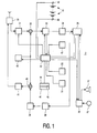
- Figure 1 is a block diagram of a portable telephone.
- the invention has been conceived in particular for use with a portable telephone, various other portable and battery powered application-speech outputting devices would benefit from the invention.
- the device may be organized as a receiver only without transmitter facility.
- the set-up of Figure has been organized largely according to European Patent EP 494 526 B1.
- the diagram has device 3 comprising a reception path and a transmission path, both coupled to antenna switch 30.
- the reception path comprises a cascade of a tunable filter 31, a mixer 32, a switchable IF_filter 33, a detector 34, a Time division Multiplex (TDMA) controller 35, a modolator 38 , an offset oscillator 39, a mixer 40, and a power amplifier 41 .
- TDMA Time division Multiplex
- a microprocessor 42 has been provided for controlling the functionality of the telephone.
- the non-volatile memory part 45 comprises a telephone functionality program.
- the device comprises power leads 48 and 49, interconnected to an exchangeable battery 51 for powering the device. By way of implication, only the powering of microprocessor 42 has been indicated.
- the device contains a microphone 27 and a loudspeaker 37 .
- the loudspeaker is low-volume, and the microphone low-sensitivity, so that during a call, the device must be kept at most a few centimeters from a user person's head.
- the housing of the device has not been indicated, but is generally conventional.
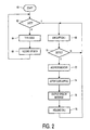
- Figure 2 is a flow diagram of a procedure according to the invention.
- operational functionalities such as by dialling a number, or even only when the device enters an application state wherein application-speech may be outputted in principle.
- application-speech could then relate to an actual telephone call, or to speech recorded on an automatic answering functionality within or remote from the device in question.
- the visual display could be used for signalling various events, in a manner that would be less distracting or less annoying to an environment. If required, the outputting of the speech items may go in parallel with the visual display.
- the device detects, such as from the actuating of a programming button, whether or not a user wants to program the device with the user's own voice. If the user signals that none or no further speech item needs to be recorded (Y), the device exits to block 68.
- the recording is executed in blocks 64, 66.
- the user inputs a particular code that has been assigned to any of a set of events that has been specified in the device's manual.
- the speech item to be outputted in relation to the particular event is recorded in the (non)volatile memory. In particular, this may be a so-called flash memory that stores the speech in compressed form.
- the compressing may be done according to one of several known procedures.
- the user programming is considered advantageous, because otherwise the number of different messages times the number of languages could overtax memory capacity.
- the loop consisting of the latter two blocks may in principle be traversed an unlimited number of times. For brevity, procedures for erasing and/or overwriting of messages have been ignored for brevity.
- the calling functionality of the device has been symbolized by block 68. By itself, this functionality is well-known and has not been detailed further.
- the device may leave the flow chart as shown, thereby allowing a next entering into block 60. Alternatively, terminating a call may automatically start such entering.
- the device may be continually looping through block 70, for therein detecting the occurrence of any of the prespecified events. If the code pertaining to a particular event is received, in block 72 the speech storing memory is addressed with an address that is derived immediately from the event code. Next, in block 74 the application-speech produced by the actual telephone call is attenuated by a certain amount, such as a few dB.
- the speech item pertaining to the event in question is outputted in superposition to the application speech present at that instant if any.
- the outputted application speech pertaining to the telephone call is resumed again at full volume, and it is left to the user person to take any appropriate measures in relation to the event just signalled.
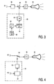
- Figure 3 shows a first embodiment of the invention as generally corresponding to the procedure of Figure 2.
- item 80 symbolizes the forming of application speech that should be presented to a user person. For a telephone application, this may be the speech communicated from the other party to a conversation.
- Attenuator element 82 is controllable through the mechanism that drives the co-presentation of the speech presentation items.
- Element 84 is an analog adder with two inputs.
- Element 86 is an analog audio amplifier.
- Element 88 is a loudspeaker.
- microcontroller element 96 provides the speech items through addressing ROM/RAM 98 with appropriate addresses. Activation of the microcontroller is through detecting the various conditions listed supra.
- Speech synthesizer item 94 is activated by the information from memory 98 and may operate according to standard speech synthesizing technology.
- Digital to analog converter item 92 converts the codes received from the speech synthesizer to analog speech signals, for presentation to analog adder 84, for superposing on the signals from the application speech channel.
- Figure 4 is a second embodiment of the invention, that has various items corresponding to Figure 3 and carrying identical labels. Instead of superposing, the embodiment has multiplexing on the speech output channel. This is effected by multiplexing switch 100 that is again controlled by the features according to the invention.
Landscapes
- Engineering & Computer Science (AREA)
- Signal Processing (AREA)
- Human Computer Interaction (AREA)
- Computer Networks & Wireless Communication (AREA)
- Telephone Function (AREA)
- Mobile Radio Communication Systems (AREA)
- Meter Arrangements (AREA)
- Machine Translation (AREA)
Claims (8)
- Verfahren, um in einer tragbaren Einrichtung, die eine Sprachverarbeitungsanwendung ausführt, und durch diese Anwendung Anwendungssprache zur Präsentation auf einem Sprachausgabekanal (36, 37) auszugeben, wobei die Einrichtung in der Nähe einer Benutzerperson positioniert ist, während in der Einrichtung ein oder mehrere, unabhängig von der Einrichtung generierte dynamische Ereignisse selektiv detektiert werden (70) und dann eine visuelle Darstellung eines dynamischen Ereignisses visuell angezeigt wird,
gekennzeichnet durch Umwandeln eines detektierten dynamischen Ereignisses in ein zugeordnetes kennzeichnendes Sprachelement (72) und Leiten des kennzeichnenden Sprachelements an den Sprachausgabekanal zur Präsentation des kennzeichnenden Sprachelements (76) an die Benutzerperson bei gleichzeitigem Fortsetzen des Ausgebens der Anwendungssprache, wodurch der Ausgabekanal alternativ in einem von zwei Zuständen gesteuert wird, um in einem ersten Zustand die Anwendungssprache allein auszugeben (78) und in einem zweiten Zustand sowohl die Anwendungssprache als auch das kennzeichnende Sprachelement auszugeben und dabei beide auf einem hinreichend wahrnehmbaren Pegel zu halten. - Verfahren nach Anspruch 1, wobei das kennzeichnende Sprachelement auf dem Anwendungssprachausgabekanal der Anwendungssprache überlagert wird (84), um das kennzeichnende Sprachelement und die Anwendungssprache in der Wahrnehmung der Benutzerperson zu kombinieren.
- Verfahren nach Anspruch 1, wobei das kennzeichnende Sprachelement mit der Anwendungssprachpräsentation an die Benutzerperson elektronisch multiplexiert wird (100).
- Verfahren nach Anspruch 1, wobei das kennzeichnende Sprachelement im Voraus von der Benutzerperson aufgezeichnet und später durch eine maschinelle Detektion des dynamischen Ereignisses selektiv zugänglich gemacht wird.
- Verfahren nach Anspruch 1 und Auswählen eines dynamischen Elements aus einem Satz von Ereignissen, der sowohl die Sprachverarbeitungsanwendung betreffende dynamische Ereignisse als auch das Einrichtungssystem betreffende dynamische Einrichtungsereignisse umfasst.
- Verfahren nach Anspruch 2, wobei die Anwendungssprache während des Überlagerns vorübergehend gedämpft wird (74).
- Tragbare Einrichtung, die zum Implementieren eines Verfahrens nach Anspruch 1 eingerichtet ist, wobei die tragbare Einrichtung zum Ausführen einer Sprachverarbeitungsanwendung eingerichtet ist und Folgendes umfasst: einen Sprachausgabekanal (88) zum Ausgeben von durch die Anwendung generierter Anwendungssprache zur Präsentation, wenn die tragbare Einrichtung in der Nähe einer Benutzerperson positioniert ist, sowie ferner Detektionsmittel (70) zum Detektieren eines oder mehrerer, unabhängig von der Einrichtung ohne Eingriff durch die Benutzerperson generierter dynamischer Ereignisse der Einrichtung und Anzeigemittel zum visuellen Anzeigen einer Darstellung eines dynamischen Ereignisses,
dadurch gekennzeichnet, dass die tragbare Einrichtung Folgendes umfasst: Umwandlungsmittel zum Umwandeln des detektierten dynamischen Ereignisses der Einrichtung in ein zugeordnetes kennzeichnendes Sprachelement (94) sowie Leitmittel zum Leiten des kennzeichnenden Sprachelements an den Sprachausgabekanal zur Präsentation der Anwendungssprache an die Benutzerperson bei gleichzeitigem Fortsetzen des Ausgebens der Anwendungssprache zusammen mit dem kennzeichnenden Sprachelement, wobei die Einrichtung Zustandssteuerungsmittel aufweist, um in einem ersten Zustand die Anwendungssprache allein auszugeben und in einem zweiten Zustand sowohl die Anwendungssprache als auch die kennzeichnenden Sprachelemente auszugeben und dabei beide auf einem hinreichend wahrnehmbaren Pegel zu halten. - Tragbare Einrichtung nach Anspruch 7 und implementiert als tragbares Gegensprechtelefon.
Priority Applications (1)
| Application Number | Priority Date | Filing Date | Title |
|---|---|---|---|
| EP98957068A EP0962085B1 (de) | 1997-12-23 | 1998-12-14 | Anmeldungsverfahren und vorrichtung mit sprachmitteilungen von ereignissen über einen sprachkanal |
Applications Claiming Priority (4)
| Application Number | Priority Date | Filing Date | Title |
|---|---|---|---|
| EP97403135 | 1997-12-23 | ||
| EP97403135 | 1997-12-23 | ||
| PCT/IB1998/002008 WO1999034573A2 (en) | 1997-12-23 | 1998-12-14 | A method and a device for speech presentation of events on a speech channel |
| EP98957068A EP0962085B1 (de) | 1997-12-23 | 1998-12-14 | Anmeldungsverfahren und vorrichtung mit sprachmitteilungen von ereignissen über einen sprachkanal |
Publications (2)
| Publication Number | Publication Date |
|---|---|
| EP0962085A2 EP0962085A2 (de) | 1999-12-08 |
| EP0962085B1 true EP0962085B1 (de) | 2006-08-02 |
Family
ID=8229933
Family Applications (1)
| Application Number | Title | Priority Date | Filing Date |
|---|---|---|---|
| EP98957068A Expired - Lifetime EP0962085B1 (de) | 1997-12-23 | 1998-12-14 | Anmeldungsverfahren und vorrichtung mit sprachmitteilungen von ereignissen über einen sprachkanal |
Country Status (7)
| Country | Link |
|---|---|
| EP (1) | EP0962085B1 (de) |
| JP (1) | JP2001513309A (de) |
| KR (1) | KR100620540B1 (de) |
| CN (1) | CN100384193C (de) |
| DE (1) | DE69835417T2 (de) |
| ES (1) | ES2270535T3 (de) |
| WO (1) | WO1999034573A2 (de) |
Citations (3)
| Publication number | Priority date | Publication date | Assignee | Title |
|---|---|---|---|---|
| US4737976A (en) * | 1985-09-03 | 1988-04-12 | Motorola, Inc. | Hands-free control system for a radiotelephone |
| EP0472289A2 (de) * | 1990-08-01 | 1992-02-26 | AT&T Corp. | Anordnung zur Zustandsumschaltung für Lautfernsprechgerät |
| WO1996019069A1 (en) * | 1994-12-12 | 1996-06-20 | Qualcomm Incorporated | Digital cellular telephone with voice feedback |
Family Cites Families (1)
| Publication number | Priority date | Publication date | Assignee | Title |
|---|---|---|---|---|
| JP2503863B2 (ja) * | 1992-08-13 | 1996-06-05 | 日本電気株式会社 | 無線電話機 |
-
1998
- 1998-12-14 EP EP98957068A patent/EP0962085B1/de not_active Expired - Lifetime
- 1998-12-14 KR KR1019997007579A patent/KR100620540B1/ko not_active Expired - Fee Related
- 1998-12-14 JP JP53469399A patent/JP2001513309A/ja active Pending
- 1998-12-14 WO PCT/IB1998/002008 patent/WO1999034573A2/en not_active Ceased
- 1998-12-14 CN CNB988041022A patent/CN100384193C/zh not_active Expired - Fee Related
- 1998-12-14 DE DE69835417T patent/DE69835417T2/de not_active Expired - Fee Related
- 1998-12-14 ES ES98957068T patent/ES2270535T3/es not_active Expired - Lifetime
Patent Citations (3)
| Publication number | Priority date | Publication date | Assignee | Title |
|---|---|---|---|---|
| US4737976A (en) * | 1985-09-03 | 1988-04-12 | Motorola, Inc. | Hands-free control system for a radiotelephone |
| EP0472289A2 (de) * | 1990-08-01 | 1992-02-26 | AT&T Corp. | Anordnung zur Zustandsumschaltung für Lautfernsprechgerät |
| WO1996019069A1 (en) * | 1994-12-12 | 1996-06-20 | Qualcomm Incorporated | Digital cellular telephone with voice feedback |
Also Published As
| Publication number | Publication date |
|---|---|
| DE69835417T2 (de) | 2007-07-05 |
| KR100620540B1 (ko) | 2006-09-06 |
| CN1252199A (zh) | 2000-05-03 |
| EP0962085A2 (de) | 1999-12-08 |
| WO1999034573A2 (en) | 1999-07-08 |
| JP2001513309A (ja) | 2001-08-28 |
| WO1999034573A3 (en) | 1999-09-02 |
| CN100384193C (zh) | 2008-04-23 |
| KR20000075520A (ko) | 2000-12-15 |
| ES2270535T3 (es) | 2007-04-01 |
| DE69835417D1 (de) | 2006-09-14 |
Similar Documents
| Publication | Publication Date | Title |
|---|---|---|
| EP2114059B1 (de) | Zellulare Mobiltelefonvorrichtung | |
| USRE39231E1 (en) | Communication terminal equipment and call incoming control method | |
| US6061435A (en) | Cordless telephone system having a handset with non-telephone functionality | |
| GB2308944A (en) | Cordless telephone with telephone answering device | |
| EP0962085B1 (de) | Anmeldungsverfahren und vorrichtung mit sprachmitteilungen von ereignissen über einen sprachkanal | |
| JPH0430646A (ja) | ボタン電話装置 | |
| EP1524827A1 (de) | Aufzeichnungssteuerungsverfahren für Mobiltelefon mit Diktierfunktionalität | |
| KR930017387A (ko) | 메세지 전달방법 및 회로 | |
| JPS647712B2 (de) | ||
| KR970005440B1 (ko) | 침입자 출현 신고 및 실황녹음 기능을 갖는 전화장치 | |
| KR100360897B1 (ko) | 메모리응답기능을 이용한 무음통화 이동전화기 | |
| KR19990005829A (ko) | 메시지 처리가 가능한 도어폰 장치 | |
| JP2687472B2 (ja) | 留守番電話装置 | |
| JP2635970B2 (ja) | 留守番電話機 | |
| JP3449184B2 (ja) | 給湯装置の遠隔制御システム | |
| KR100247052B1 (ko) | 자동응답 전화기에서 통화중 음성메시지 전송방법 | |
| JP2549641B2 (ja) | 留守番電話機能付きフアクシミリ装置 | |
| JPH10271189A (ja) | 携帯電話機 | |
| JP2753188B2 (ja) | 有線通信端末機 | |
| KR950001547B1 (ko) | 자동응답 전화기의 송출 메세지 스킵에 의한 수신 메세지 저장방법 | |
| JPH0612910B2 (ja) | 機能電話機 | |
| KR20030003832A (ko) | 휴대용 통신단말기에서의 자동응답을 제공하는 방법 | |
| JPH04299645A (ja) | コードレスホン付ファクシミリ装置 | |
| KR970009108A (ko) | 전화착신 자동녹음 장치 | |
| JPH10210136A (ja) | 携帯電話機 |
Legal Events
| Date | Code | Title | Description |
|---|---|---|---|
| PUAI | Public reference made under article 153(3) epc to a published international application that has entered the european phase |
Free format text: ORIGINAL CODE: 0009012 |
|
| 17P | Request for examination filed |
Effective date: 19990923 |
|
| AK | Designated contracting states |
Kind code of ref document: A2 Designated state(s): DE ES FR GB IT |
|
| 17Q | First examination report despatched |
Effective date: 20050617 |
|
| GRAP | Despatch of communication of intention to grant a patent |
Free format text: ORIGINAL CODE: EPIDOSNIGR1 |
|
| GRAS | Grant fee paid |
Free format text: ORIGINAL CODE: EPIDOSNIGR3 |
|
| GRAA | (expected) grant |
Free format text: ORIGINAL CODE: 0009210 |
|
| AK | Designated contracting states |
Kind code of ref document: B1 Designated state(s): DE ES FR GB IT |
|
| REG | Reference to a national code |
Ref country code: GB Ref legal event code: FG4D |
|
| REF | Corresponds to: |
Ref document number: 69835417 Country of ref document: DE Date of ref document: 20060914 Kind code of ref document: P |
|
| ET | Fr: translation filed | ||
| REG | Reference to a national code |
Ref country code: ES Ref legal event code: FG2A Ref document number: 2270535 Country of ref document: ES Kind code of ref document: T3 |
|
| PLBE | No opposition filed within time limit |
Free format text: ORIGINAL CODE: 0009261 |
|
| STAA | Information on the status of an ep patent application or granted ep patent |
Free format text: STATUS: NO OPPOSITION FILED WITHIN TIME LIMIT |
|
| 26N | No opposition filed |
Effective date: 20070503 |
|
| PGFP | Annual fee paid to national office [announced via postgrant information from national office to epo] |
Ref country code: IT Payment date: 20081217 Year of fee payment: 11 |
|
| PGFP | Annual fee paid to national office [announced via postgrant information from national office to epo] |
Ref country code: ES Payment date: 20090129 Year of fee payment: 11 |
|
| PGFP | Annual fee paid to national office [announced via postgrant information from national office to epo] |
Ref country code: DE Payment date: 20090220 Year of fee payment: 11 |
|
| PGFP | Annual fee paid to national office [announced via postgrant information from national office to epo] |
Ref country code: FR Payment date: 20081219 Year of fee payment: 11 |
|
| PGFP | Annual fee paid to national office [announced via postgrant information from national office to epo] |
Ref country code: GB Payment date: 20091230 Year of fee payment: 12 |
|
| REG | Reference to a national code |
Ref country code: FR Ref legal event code: ST Effective date: 20100831 |
|
| PG25 | Lapsed in a contracting state [announced via postgrant information from national office to epo] |
Ref country code: FR Free format text: LAPSE BECAUSE OF NON-PAYMENT OF DUE FEES Effective date: 20091231 |
|
| PG25 | Lapsed in a contracting state [announced via postgrant information from national office to epo] |
Ref country code: DE Free format text: LAPSE BECAUSE OF NON-PAYMENT OF DUE FEES Effective date: 20100701 |
|
| PG25 | Lapsed in a contracting state [announced via postgrant information from national office to epo] |
Ref country code: IT Free format text: LAPSE BECAUSE OF NON-PAYMENT OF DUE FEES Effective date: 20091214 |
|
| REG | Reference to a national code |
Ref country code: ES Ref legal event code: FD2A Effective date: 20110408 |
|
| PG25 | Lapsed in a contracting state [announced via postgrant information from national office to epo] |
Ref country code: ES Free format text: LAPSE BECAUSE OF NON-PAYMENT OF DUE FEES Effective date: 20110324 |
|
| GBPC | Gb: european patent ceased through non-payment of renewal fee |
Effective date: 20101214 |
|
| PG25 | Lapsed in a contracting state [announced via postgrant information from national office to epo] |
Ref country code: ES Free format text: LAPSE BECAUSE OF NON-PAYMENT OF DUE FEES Effective date: 20091215 |
|
| PG25 | Lapsed in a contracting state [announced via postgrant information from national office to epo] |
Ref country code: GB Free format text: LAPSE BECAUSE OF NON-PAYMENT OF DUE FEES Effective date: 20101214 |