EP0472037B1 - Vollschlauchzapfventil - Google Patents
Vollschlauchzapfventil Download PDFInfo
- Publication number
- EP0472037B1 EP0472037B1 EP91113080A EP91113080A EP0472037B1 EP 0472037 B1 EP0472037 B1 EP 0472037B1 EP 91113080 A EP91113080 A EP 91113080A EP 91113080 A EP91113080 A EP 91113080A EP 0472037 B1 EP0472037 B1 EP 0472037B1
- Authority
- EP
- European Patent Office
- Prior art keywords
- valve
- full
- dispensing nozzle
- outlet
- pulse generator
- Prior art date
- Legal status (The legal status is an assumption and is not a legal conclusion. Google has not performed a legal analysis and makes no representation as to the accuracy of the status listed.)
- Expired - Lifetime
Links
- 239000000446 fuel Substances 0.000 title claims abstract description 5
- 230000001105 regulatory effect Effects 0.000 claims abstract description 4
- 239000007788 liquid Substances 0.000 claims abstract 2
- 238000002156 mixing Methods 0.000 claims description 18
- 230000006835 compression Effects 0.000 claims description 5
- 238000007906 compression Methods 0.000 claims description 5
- 230000001141 propulsive effect Effects 0.000 claims 3
- 238000007789 sealing Methods 0.000 description 4
- 230000000712 assembly Effects 0.000 description 3
- 238000000429 assembly Methods 0.000 description 3
- 238000001704 evaporation Methods 0.000 description 3
- 230000008020 evaporation Effects 0.000 description 3
- 239000012528 membrane Substances 0.000 description 3
- 239000000203 mixture Substances 0.000 description 3
- 230000015572 biosynthetic process Effects 0.000 description 2
- 238000011161 development Methods 0.000 description 2
- 230000018109 developmental process Effects 0.000 description 2
- 230000002159 abnormal effect Effects 0.000 description 1
- 238000000889 atomisation Methods 0.000 description 1
- 230000005540 biological transmission Effects 0.000 description 1
- 230000001276 controlling effect Effects 0.000 description 1
- 230000007423 decrease Effects 0.000 description 1
- 238000006073 displacement reaction Methods 0.000 description 1
- 230000000694 effects Effects 0.000 description 1
- 239000000945 filler Substances 0.000 description 1
- 239000012530 fluid Substances 0.000 description 1
- 239000006260 foam Substances 0.000 description 1
- 238000005187 foaming Methods 0.000 description 1
- 238000000034 method Methods 0.000 description 1
- 230000001681 protective effect Effects 0.000 description 1
Images
Classifications
-
- B—PERFORMING OPERATIONS; TRANSPORTING
- B67—OPENING, CLOSING OR CLEANING BOTTLES, JARS OR SIMILAR CONTAINERS; LIQUID HANDLING
- B67D—DISPENSING, DELIVERING OR TRANSFERRING LIQUIDS, NOT OTHERWISE PROVIDED FOR
- B67D7/00—Apparatus or devices for transferring liquids from bulk storage containers or reservoirs into vehicles or into portable containers, e.g. for retail sale purposes
- B67D7/06—Details or accessories
- B67D7/42—Filling nozzles
- B67D7/44—Filling nozzles automatically closing
- B67D7/46—Filling nozzles automatically closing when liquid in container to be filled reaches a predetermined level
- B67D7/48—Filling nozzles automatically closing when liquid in container to be filled reaches a predetermined level by making use of air suction through an opening closed by the rising liquid
-
- B—PERFORMING OPERATIONS; TRANSPORTING
- B67—OPENING, CLOSING OR CLEANING BOTTLES, JARS OR SIMILAR CONTAINERS; LIQUID HANDLING
- B67D—DISPENSING, DELIVERING OR TRANSFERRING LIQUIDS, NOT OTHERWISE PROVIDED FOR
- B67D7/00—Apparatus or devices for transferring liquids from bulk storage containers or reservoirs into vehicles or into portable containers, e.g. for retail sale purposes
- B67D7/06—Details or accessories
- B67D7/42—Filling nozzles
- B67D7/44—Filling nozzles automatically closing
- B67D7/52—Filling nozzles automatically closing and provided with additional flow-controlling valve means
Definitions
- the invention relates to a full hose nozzle according to the preamble of claim 1.
- a disadvantage of these nozzle valves is not only the mechanical connection of the main valve and the pulse generator, which is expensive.
- a fuel-air mixture is also delivered with these nozzle valves by the addition of air by means of jet systems for actuating the main valve, which has the consequence that the added air has higher flow velocities and thus causes faster atomization of the jet, which favors more intensive fuel evaporation.
- the fuel-air mixture dissolves again in the tank, and it is not uncommon for large air bubbles to form in the tank during full refueling, which gush out intermittently and allow fuel to spill out of the filler neck.
- the automatic switch-off only speaks at approx. 5 1 / min. Dispensing quantity so that when the valve is open and due to abnormal throttling of the inflow quantity, automatic closing is no longer guaranteed.
- the object of the invention is to provide a dispensing valve for full hose dispensing systems which is switchable even at a low flow rate, does not promote foam formation in the medium emitted by admixing air, avoids loss of medium due to design and reduces the evaporation of medium and is easy to operate and can be manufactured and maintained inexpensively.
- This inventive design of the nozzle with a hydraulically controlled main valve and the inventive division of the essential elements of the nozzle in the assembly, namely the main valve, the control valve and the pulse generator, can be dispensed with structurally complex mechanical elements that connect these assemblies, whereby a particularly light nozzle is obtained and adjustment and adjustment work is largely eliminated.
- the hydraulic control not only prevents the nozzle from opening when the inlet pressure is too low.
- the main valve is also gently closed, since no mechanical interlocks have to be released for this, in particular in the case of automatic switch-off, as a result of which pressure surges or impacts in the supply system of the valve are prevented.
- control valve has a valve cone attached to a push rod which can be adjusted by the actuating lever and a membrane which seals the valve housing and the push rod to the outside. This also ensures that when the nozzle is switched off automatically due to the increasing pressure of the medium in the control valve, not only is this valve closed, but at the same time the push rod and thus the actuating lever are returned to the starting position.
- the pulse generator has a propulsion jet nozzle which is connected to the control valve and blows off the medium supplied to it from the control valve into a mixing tube which is movably arranged in the pulse generator, with one between the mixing tube and the propulsion jet nozzle the vacuum chamber connected to the outlet of the nozzle and formed on the opposite of the jet nozzle
- the housing of a poppet valve is provided, the valve disk of which is connected to the mixing tube.
- This inventive design of the pulse generator as an ejector or jet pump and the mixing tube with attached valve disk of a poppet valve as a slide sliding in the pulse generator provides a simple control element which not only initiates the automatic closing of the nozzle when the container is full, but also prevents the nozzle from opening when its outlet points upwards.
- the operating lever can be locked.
- the actuating lever with a locking mechanism which can be set against the restoring force exerted by the membrane on the push rod, and which unlocks when the valve is closed, so that the actuating lever can be returned to its initial position.
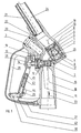
- the full hose nozzle shown consists of a housing 15 in which the three main assemblies, the main valve 1, the control valve 2 and the hydraulic pulse generator 3, which can be installed independently of one another, are used.
- the hydraulically controlled main valve 1 has one Valve guide 4, in which a valve body 5 slides, which is provided on the inside with a sealing disk 6, on which the valve cone 7 of a servo valve comes to rest.
- a control bore 18 is machined into the valve body 5, via which the interior of the valve can be filled with medium.
- the valve cone 7 of the servo valve slides in a guide sleeve 8.
- the pressure chamber 9 formed within the valve cone 7 and the guide sleeve 8 is filled with a medium under pressure in the inlet 23 via a bore 16 acting as a nozzle in the housing 11 of the control valve 2 and the connecting channel 17 . As a result, the valve cone 7 is pressed against the sealing disk 6.
- This control valve 2 with which the main valve 1 can be regulated, opened, closed or the desired flow rate of the nozzle valve can be set, also has a pushrod 26 attached to the valve cone 12 and adjustable by the actuating lever 14, and a diaphragm 13 which seals the valve housing 11 and the push rod 26 seals to the outside.
- the pressure chamber 9 is simultaneously filled with medium. There is a pressure equalization of the pressure in the inlet 23 of the nozzle via the control valve 2 to the pressure chamber 9.
- the pressure in the valve housing 11 decreases as soon as the control valve 2 is opened by lifting the valve cone 12. As a result, the pressure in the pressure chamber 9 also drops, so that the main valve opens.
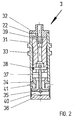
- This pulse generator 3 is a switching element that takes over switching functions with low media flow from low pressure and controls the automatic switching off of the nozzle valve.
- This pulse generator has a drive jet nozzle 32 which is connected to the control valve 2 via the channel 19 and which blows off the medium supplied to it from the channel 19 into a mixing tube 33 which is movably arranged in the pulse generator housing 31.
- a vacuum chamber 39 is formed between the mixing tube 33 and the driving jet nozzle 32 and is connected via a channel 22 to a channel 21 provided in the outlet 24 of the nozzle.
- a poppet valve housing 34 is also provided on the side of the mixing tube 33 opposite the driving jet nozzle 32, the valve disc 35 of which is connected to the mixing tube 33 via a valve rod 37 and a bolt 38. With the valve disc 35, which is perforated, an annular groove 41 can be closed, via which the pulse generator 3 supplied medium in the channel 20 to the outlet 24.
- the medium supplied to the pulse generator 3 and emerging from the jet nozzle 32 sucks air from the container to be filled with the nozzle via the vacuum chamber 39 and the channels 21 and 22.
- This air mixes in the mixing tube 33 with the medium from the jet nozzle 32 and flows as a mixture via the annular groove 41 and the channel 20 into the outlet 24. If the air supply, for. B. because the mouth of the channel 21, not shown, was closed by the medium fed into the container to be filled, hindered or interrupted via the channel 22 to the vacuum chamber 39, the mixing tube 33 moves as a result of the increasing negative pressure effect in the vacuum chamber 39 in the direction of the jet nozzle 32 and closes the mouth of the channel 22 into the vacuum chamber 39.
- the poppet valve disk 35 is also moved closer to the annular groove 41 and hinders the outflow of the medium which has entered the pulse generator 3 via the channel 19.
- the annular groove 41 creates a space 40 between this disk 35 and the bottom 36 of the pulse generator 3, into which medium can flow. This supports the displacement of the mixing tube 33 in the direction of the jet nozzle 32 and the poppet valve disc 35 is drawn against the annular groove 41.
- the hydraulic pulse generator 3 is now closed, so that no medium can flow out of the channel 19, which creates a pressure build-up in this channel and the pressure in the control valve 2 and the pressure chamber 9 increases and the main valve 1 closes.
- the control valve 2 is still open because the switching off of the nozzle valve was caused by the hydraulic pulse generator 3. Due to the still open control valve 2, the increasing pressure also acts on the diaphragm 13, which is fastened to the push rod 26 of the valve cone 12 and not only brings the actuating lever 14 into its starting position, but also closes the control valve 2. The closing function of the nozzle valve is again taken over by the now closed control valve 2. The pressure in the still closed pulse generator 3 is not only balanced between the two sides through the perforated poppet valve disk 35.
- a locking device which comprises a pawl 42.
- the pawl 42 is articulated on a sliding piece 44 which can be displaced in the actuating lever 14 against the force of a compression spring 43 and can be hooked into a recess of a locking bar 27 on the protective bracket 28 of the nozzle valve against a force of a leg spring 42 acting on the pawl 42 in a clockwise direction.
- the actuating lever 14 is adjusted until the desired amount of media is dispensed from the nozzle and in this position is determined by the locking mechanism, by means of a latch lever 30 likewise articulated on the actuating lever 14, the pawl in such a position in which the axes of the pawl 42 and the sliding piece 44 are not aligned and the end of the pawl 42 to be hooked away from the housing 15 of the nozzle valve is brought into engagement with the corresponding recess of the locking bar 27.
- the holding force of the pawl 42 is only so great that it withstands the low pressure in the control valve 2 when the pulse generator 3 is open.
- This holding force can be determined via an adjusting nut 45 on the sliding piece 44, by adjusting the support angle of the pawl 42 by changing the position of the sliding piece 44 in the actuating lever 14.
- the main valve 1 is used in the nozzle so that there is a small flow path between the main valve 1 and the outlet 24, which is emptied immediately when the valve is closed.
- the control valve 2 is opened, the hydraulic pulse generator 3 is ready for operation before the main valve 1 begins to open.
- the shut-off valve can be switched off automatically even when the quantity dispensed is very low.
- the formation of the mixing tube 33 as a slidable slide in the hydraulic pulse generator 3 also causes the nozzle to close itself when the outlet 24 is pointing upwards, so that no media delivery is possible in this state.
Landscapes
- Engineering & Computer Science (AREA)
- Mechanical Engineering (AREA)
- Loading And Unloading Of Fuel Tanks Or Ships (AREA)
- Multiple-Way Valves (AREA)
- Mechanically-Actuated Valves (AREA)
- Catching Or Destruction (AREA)
- On-Site Construction Work That Accompanies The Preparation And Application Of Concrete (AREA)
Priority Applications (1)
| Application Number | Priority Date | Filing Date | Title |
|---|---|---|---|
| AT91113080T ATE97389T1 (de) | 1990-08-08 | 1991-08-03 | Vollschlauchzapfventil. |
Applications Claiming Priority (2)
| Application Number | Priority Date | Filing Date | Title |
|---|---|---|---|
| DD90343318A DD297136A5 (de) | 1990-08-08 | 1990-08-08 | Zapfventil fuer vollschlauch-zapfanlagen |
| DD343318 | 1990-08-08 |
Publications (2)
| Publication Number | Publication Date |
|---|---|
| EP0472037A1 EP0472037A1 (de) | 1992-02-26 |
| EP0472037B1 true EP0472037B1 (de) | 1993-11-18 |
Family
ID=5620180
Family Applications (1)
| Application Number | Title | Priority Date | Filing Date |
|---|---|---|---|
| EP91113080A Expired - Lifetime EP0472037B1 (de) | 1990-08-08 | 1991-08-03 | Vollschlauchzapfventil |
Country Status (7)
| Country | Link |
|---|---|
| EP (1) | EP0472037B1 (cs) |
| JP (1) | JPH05170300A (cs) |
| AT (1) | ATE97389T1 (cs) |
| CA (1) | CA2048833A1 (cs) |
| CS (1) | CS241091A3 (cs) |
| DD (1) | DD297136A5 (cs) |
| DE (2) | DE9109596U1 (cs) |
Family Cites Families (3)
| Publication number | Priority date | Publication date | Assignee | Title |
|---|---|---|---|---|
| US3152623A (en) * | 1961-06-09 | 1964-10-13 | Satam Sa Pour Tous App S Mecan | Liquid flow control apparatus |
| US3638689A (en) * | 1969-05-29 | 1972-02-01 | Ljungmans Verkstader Ab | Automatic dispensing nozzle |
| DE3528612C1 (de) * | 1985-08-09 | 1986-12-11 | Karlheinz 2000 Hamburg Ehlers | Zapfpistole fuer Kraftstoff mit fuellhoehenabhaengiger Abschaltautomatik und pumpendruckabhaengiger Sicherheitsvorrichtung |
-
1990
- 1990-08-08 DD DD90343318A patent/DD297136A5/de not_active IP Right Cessation
-
1991
- 1991-08-02 CS CS912410A patent/CS241091A3/cs unknown
- 1991-08-02 DE DE9109596U patent/DE9109596U1/de not_active Expired - Lifetime
- 1991-08-03 DE DE91113080T patent/DE59100607D1/de not_active Expired - Fee Related
- 1991-08-03 EP EP91113080A patent/EP0472037B1/de not_active Expired - Lifetime
- 1991-08-03 AT AT91113080T patent/ATE97389T1/de not_active IP Right Cessation
- 1991-08-08 JP JP3199044A patent/JPH05170300A/ja active Pending
- 1991-08-08 CA CA002048833A patent/CA2048833A1/en not_active Abandoned
Also Published As
| Publication number | Publication date |
|---|---|
| EP0472037A1 (de) | 1992-02-26 |
| CS241091A3 (en) | 1992-03-18 |
| CA2048833A1 (en) | 1992-02-09 |
| JPH05170300A (ja) | 1993-07-09 |
| DE9109596U1 (de) | 1992-01-30 |
| DE59100607D1 (de) | 1993-12-23 |
| DD297136A5 (de) | 1992-01-02 |
| ATE97389T1 (de) | 1993-12-15 |
Similar Documents
| Publication | Publication Date | Title |
|---|---|---|
| DE69812414T2 (de) | Ventil | |
| DE2023721A1 (de) | Spritzpistole | |
| EP2427678A1 (de) | Fluidventil, insbesondere rückführventil für eine lackieranlage | |
| DE2900835A1 (de) | Steuerventil | |
| WO1999013253A1 (de) | Überströmventil | |
| DE3528612C1 (de) | Zapfpistole fuer Kraftstoff mit fuellhoehenabhaengiger Abschaltautomatik und pumpendruckabhaengiger Sicherheitsvorrichtung | |
| DE2746037A1 (de) | Hochdruckreinigungsgeraet | |
| DE3105284C2 (cs) | ||
| DE1273884B (de) | Druckregulierungseinrichtung | |
| DE3446651A1 (de) | Druckbetaetigtes ventil fuer treibstoffzapfstutzen | |
| EP0472037B1 (de) | Vollschlauchzapfventil | |
| DE2531393A1 (de) | Druckgesteuerte ventilanordnung | |
| DE69413756T2 (de) | Einspritz- und Regelvorrichtung für atmosphärische Gasbrenner von Heizgeräte, insbesondere der Infrarottyp | |
| DE9011041U1 (de) | Vollschlauchzapfventil | |
| DE2813242A1 (de) | Automatisch absperrender zapfhahn | |
| DE1625216B2 (de) | Verfahren zur betriebssteuerung einer spritzvorrichtung fuer verschiedene reinigungsfluessigkeiten und vorrichtung zur ausfuehrung des verfahrens | |
| DE2239484B2 (de) | Druckgesteuerte Dosiervorrichtung für Flüssigkeiten | |
| DE2346299A1 (de) | Regelbare strahlpumpe, insbesondere fuer heizungsanlagen | |
| DE628474C (de) | Druckregler fuer das Druckregelventil der Fluessigkeitsbremse eines Kraftfahrzeuges | |
| DE2302220A1 (de) | Vorrichtung zum fuellen von behaeltern | |
| EP3974374B1 (de) | Zapfpistole mit schalter zwischen zwei maximalen durchflussraten | |
| EP0473001B1 (de) | Anordnung zur Durchflussmengenregelung und zum Öffnen eines Durchflusskanals für unter Druck stehende Flüssigkeiten | |
| DE1900938C3 (de) | Automatische Geschwindigkeitssteuerung für den Antrieb eines Kraftfahrzeuges | |
| DE728849C (de) | Umsteuervorrichtung fuer Fluessigkeiten oder Gase | |
| DD295424A5 (de) | Hydraulischer impulsgeber |
Legal Events
| Date | Code | Title | Description |
|---|---|---|---|
| PUAI | Public reference made under article 153(3) epc to a published international application that has entered the european phase |
Free format text: ORIGINAL CODE: 0009012 |
|
| AK | Designated contracting states |
Kind code of ref document: A1 Designated state(s): AT BE CH DE DK ES FR GB GR IT LI NL SE |
|
| 17P | Request for examination filed |
Effective date: 19920327 |
|
| 17Q | First examination report despatched |
Effective date: 19920703 |
|
| GRAA | (expected) grant |
Free format text: ORIGINAL CODE: 0009210 |
|
| AK | Designated contracting states |
Kind code of ref document: B1 Designated state(s): AT BE CH DE DK ES FR GB GR IT LI NL SE |
|
| PG25 | Lapsed in a contracting state [announced via postgrant information from national office to epo] |
Ref country code: IT Free format text: LAPSE BECAUSE OF FAILURE TO SUBMIT A TRANSLATION OF THE DESCRIPTION OR TO PAY THE FEE WITHIN THE PRE;WARNING: LAPSES OF ITALIAN PATENTS WITH EFFECTIVE DATE BEFORE 2007 MAY HAVE OCCURRED AT ANY TIME BEFORE 2007. THE CORRECT EFFECTIVE DATE MAY BE DIFFERENT FROM THE ONE RECORDED.SCRIBED TIME-LIMIT Effective date: 19931118 Ref country code: ES Free format text: THE PATENT HAS BEEN ANNULLED BY A DECISION OF A NATIONAL AUTHORITY Effective date: 19931118 Ref country code: GR Free format text: LAPSE BECAUSE OF FAILURE TO SUBMIT A TRANSLATION OF THE DESCRIPTION OR TO PAY THE FEE WITHIN THE PRESCRIBED TIME-LIMIT Effective date: 19931118 Ref country code: BE Effective date: 19931118 Ref country code: DK Effective date: 19931118 Ref country code: GB Effective date: 19931118 Ref country code: FR Free format text: THE PATENT HAS BEEN ANNULLED BY A DECISION OF A NATIONAL AUTHORITY Effective date: 19931118 Ref country code: NL Effective date: 19931118 Ref country code: SE Effective date: 19931118 |
|
| REF | Corresponds to: |
Ref document number: 97389 Country of ref document: AT Date of ref document: 19931215 Kind code of ref document: T |
|
| REF | Corresponds to: |
Ref document number: 59100607 Country of ref document: DE Date of ref document: 19931223 |
|
| NLV1 | Nl: lapsed or annulled due to failure to fulfill the requirements of art. 29p and 29m of the patents act | ||
| GBV | Gb: ep patent (uk) treated as always having been void in accordance with gb section 77(7)/1977 [no translation filed] |
Effective date: 19931118 |
|
| PG25 | Lapsed in a contracting state [announced via postgrant information from national office to epo] |
Ref country code: AT Effective date: 19940803 |
|
| PG25 | Lapsed in a contracting state [announced via postgrant information from national office to epo] |
Ref country code: CH Effective date: 19940831 Ref country code: LI Effective date: 19940831 |
|
| PLBE | No opposition filed within time limit |
Free format text: ORIGINAL CODE: 0009261 |
|
| STAA | Information on the status of an ep patent application or granted ep patent |
Free format text: STATUS: NO OPPOSITION FILED WITHIN TIME LIMIT |
|
| 26N | No opposition filed | ||
| REG | Reference to a national code |
Ref country code: CH Ref legal event code: PL |
|
| PG25 | Lapsed in a contracting state [announced via postgrant information from national office to epo] |
Ref country code: DE Effective date: 19950503 |