EP0471171A2 - Dispositif pour la régulation et le limitation de la puissance d'une surface de chauffage en céramique ou un matériau similaire - Google Patents
Dispositif pour la régulation et le limitation de la puissance d'une surface de chauffage en céramique ou un matériau similaire Download PDFInfo
- Publication number
- EP0471171A2 EP0471171A2 EP91110463A EP91110463A EP0471171A2 EP 0471171 A2 EP0471171 A2 EP 0471171A2 EP 91110463 A EP91110463 A EP 91110463A EP 91110463 A EP91110463 A EP 91110463A EP 0471171 A2 EP0471171 A2 EP 0471171A2
- Authority
- EP
- European Patent Office
- Prior art keywords
- heating
- temperature
- glass ceramic
- zone
- heating elements
- Prior art date
- Legal status (The legal status is an assumption and is not a legal conclusion. Google has not performed a legal analysis and makes no representation as to the accuracy of the status listed.)
- Granted
Links
Images


Classifications
-
- H—ELECTRICITY
- H05—ELECTRIC TECHNIQUES NOT OTHERWISE PROVIDED FOR
- H05B—ELECTRIC HEATING; ELECTRIC LIGHT SOURCES NOT OTHERWISE PROVIDED FOR; CIRCUIT ARRANGEMENTS FOR ELECTRIC LIGHT SOURCES, IN GENERAL
- H05B3/00—Ohmic-resistance heating
- H05B3/68—Heating arrangements specially adapted for cooking plates or analogous hot-plates
- H05B3/74—Non-metallic plates, e.g. vitroceramic, ceramic or glassceramic hobs, also including power or control circuits
- H05B3/746—Protection, e.g. overheat cutoff, hot plate indicator
-
- H—ELECTRICITY
- H05—ELECTRIC TECHNIQUES NOT OTHERWISE PROVIDED FOR
- H05B—ELECTRIC HEATING; ELECTRIC LIGHT SOURCES NOT OTHERWISE PROVIDED FOR; CIRCUIT ARRANGEMENTS FOR ELECTRIC LIGHT SOURCES, IN GENERAL
- H05B2213/00—Aspects relating both to resistive heating and to induction heating, covered by H05B3/00 and H05B6/00
- H05B2213/04—Heating plates with overheat protection means
-
- H—ELECTRICITY
- H05—ELECTRIC TECHNIQUES NOT OTHERWISE PROVIDED FOR
- H05B—ELECTRIC HEATING; ELECTRIC LIGHT SOURCES NOT OTHERWISE PROVIDED FOR; CIRCUIT ARRANGEMENTS FOR ELECTRIC LIGHT SOURCES, IN GENERAL
- H05B2213/00—Aspects relating both to resistive heating and to induction heating, covered by H05B3/00 and H05B6/00
- H05B2213/05—Heating plates with pan detection means
-
- H—ELECTRICITY
- H05—ELECTRIC TECHNIQUES NOT OTHERWISE PROVIDED FOR
- H05B—ELECTRIC HEATING; ELECTRIC LIGHT SOURCES NOT OTHERWISE PROVIDED FOR; CIRCUIT ARRANGEMENTS FOR ELECTRIC LIGHT SOURCES, IN GENERAL
- H05B2213/00—Aspects relating both to resistive heating and to induction heating, covered by H05B3/00 and H05B6/00
- H05B2213/07—Heating plates with temperature control means
Definitions
- the invention relates to a method for power control and limitation in a heating surface made of glass ceramic or a comparable material, in particular a glass ceramic cooking surface, the individual heating zones of the heating surface being heated in a manner known per se with heating devices with a plurality of independently switchable and controllable heating elements.
- the invention further relates to a preferred device for carrying out the method in a hob with a glass ceramic hob.
- Heating surfaces made of glass ceramic or a comparable material are also used, for example, as wall or ceiling radiators, heat exchangers or other large-area heating devices which can be heated in any way.
- the heating power for the heating devices is set permanently by the user or electronically, electromechanically or, in the case of gas stoves, by means of a selectable time program via valves, purely mechanically controlled.
- Corresponding controls are described for example in the patent specification DE-PS 3 639 186 A1.
- DE-OS 33 14 501 A 1 describes a heating plate with two concentric heating circuits, in which the outer heating circuit is designed as an auxiliary heating circuit.
- DE-PS 34 06 604 relates to a heating device in which the heating zone is heated by means of several high and normal temperature radiation heating elements.
- the heating elements are arranged in such a way that the heating point is divided into two concentric zones, the inner zone being heated only by the high-temperature radiation heating elements which can preferably be used as auxiliary heating elements in the boiling phase and the outer zone by the normal-temperature radiation heating elements.
- a comparable arrangement of several radiant heating elements in the area of a cooking zone can also be found in US Pat. No. 4,639,579.
- a heating device with a gas burner which has two burner chambers which can be acted upon independently of one another and which, for example, Can limit concentric zones in the cooking zone area is described in US Pat. No. 4,083,355.
- Protective temperature limiter for example between the heating elements and the glass ceramic surface mostly along a diameter arranged rod expansion switches, which usually switch off the heating device completely or reduce its performance when a certain limit temperature is exceeded. After running through a hysteresis, the full heating output is switched on again. From DE-OS 3 314 501, for example, a rod expansion switch with two different switching points is known, which switches accordingly at two different temperatures.
- the abnormal loading conditions described above can lead to damage to the glass ceramic cooktop on the one hand and on the other hand considerably impair the efficiency of the cooking system.
- the object of the invention is to provide an improved method for power control and limitation in the case of a heating surface made of glass ceramic or a comparable material, in particular in the case of a glass ceramic cooking surface, which enables the cooking system to be used optimally even when poor cookware is used, but also the thermal load to keep the heating surface small.
- Another object of the invention is to provide a suitable device for carrying out the method in a hob with a glass ceramic hob.
- the temperature distribution in the heating zone is recorded with a plurality of independent temperature sensors arranged in the area of a heating zone, which can be integrated into the cooking zone area, for example, and the temperature signals obtained therefrom are used to detect the temperature distribution in the heating zone Switching and controlling the heating elements or heating circuits assigned to the heating zone independently of one another in such a way that the power distribution and thus the surface load of the heating zone is adapted to the locally different heat flow, which, for example, depends on the geometry of the support surface of the pots placed on the hob.
- heating takes place, for example, even when the pot quality is poor, with optimal heating output, while in places where there is little heat extraction, the heating output is prevented by overheating by reducing the number of cycles, for example.
- the conversion of the temperature measurement signals into control signals for the power supply of the heating elements is carried out with the help of control devices known per se.
- the power supply for the heating elements is interrupted until the temperature in the assigned overheated cooking zone area is again below the threshold temperature.
- the full heating output is then switched on again.
- the power supply for the heating elements is reduced continuously or stepwise at intervals, for example to a level which is reduced by at least 10%, until the heating power of the heating elements is optimally matched to the maximum possible heat removal in the assigned area of the heating zone is adapted.
- the gradual power reduction at different switching temperatures can take place in a manner known per se in such a way that for each switching temperature there is a separate temperature sensor in the area of the heating zone assigned to the respective heating element.
- Mutually independent temperature sensors in the sense of this invention can be, for example, electromechanical temperature sensors with a plurality of mutually independent switching contacts, such as the known rod expansion switches, for example in the form of capillaries filled with molten salt, with several, but at least two, mutually independent switching contacts.
- the switching contact which limits the maximum surface temperature, should advantageously respond at a temperature which is at least 10 K above the switching temperatures of the other switching contacts, with the aid of which the power is reduced.
- Thermally conductive rods or sheets or the like can also be used as temperature sensors, to which the actual temperature sensor is coupled outside the radiator or the heated zone.
- thermocouples or other suitable temperature sensors arranged in the form of a grid in the area of the heating zone. In order to ensure sufficient thermal contact with the heating surface, these must be pressed onto the heating surface. Such temperature sensors can also be integrated into the heating surface. For example, thermocouples can be embedded or rolled into the heating surface.
- the temperature sensors known from DE-PS 21 39 828 and integrated into the heating surfaces are preferably used.
- two parallel conductor tracks are applied to the heating surface in the area of the heating zones in a manner known per se, for example by means of screen printing or vapor deposition or other methods, and then baked.
- the very strong temperature-dependent electrical resistance of the glass ceramic delimited between the conductor tracks represents the actual temperature sensor.
- large-scale temperature sensors of any shape can be implemented in a simple manner, which permit area-wide temperature monitoring.
- This can also be used, for example Monitor and control large-area heat radiators and heat exchangers with heating surfaces made of glass ceramic, glass or similar materials.
- the geometrical arrangement of the conductor tracks in the region of a heating zone is expediently adapted to the geometrical arrangement of the heating elements and to the expected temperature distribution in the case of known anomalous thermal load cases.
- the temperature sensors advantageously detect all essential parts of the heated areas of the heating zone assigned to the heating elements, so that local overheating is also detected. For example, heating coil loops or in the area of flame tips, e.g. with gas heating, higher temperatures occur at these points than neighboring points. These temperature peaks must be recorded, otherwise the heating surface can be damaged at these points.
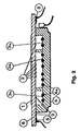
- FIGS. 1 and 2 show an example of a device which is particularly suitable for carrying out the method according to the invention in a hob with a glass ceramic hob.
- gold conductor tracks (2) are arranged within the cooking zone (1) of a glass ceramic hob on the glass ceramic underside.
- the conductor track is selected such that the outer circle (3a) and the inner circle (3b) of a two-circuit heating element (4) are each covered with ring-shaped conductor tracks.
- the connection areas (5) lie outside the cooking zone (1) for protection against thermal loads.
- Figure 2 shows the arrangement consisting of the glass ceramic plate (6), the two-circuit heating element (4) with the heating coils (4a) and the printed conductors (2) printed on the underside of the glass ceramic and the connection areas (5) in section.
- the invention is in no way limited to the use of the two-circuit heating elements shown in FIGS. 1 and 2.
- any heating device can be used that is composed of several heating elements that can be switched and controlled independently of one another in the area of a cooking zone.
- the invention can e.g. can also be used with gas burners, e.g. also in the gas burner known from US Pat. No. 4,083,355 with two burner chambers which can be acted upon independently of one another by fuel.
- the heating elements can e.g. be arranged in a grid below the cooking zone.
- the geometric arrangement of the heating elements is advantageously adapted to the geometry of the cookware or to the temperature distribution in the cooking zone area in the case of known anomalous thermal loads, so that effective control of the power distribution to the locally different heat extraction is possible.
- the conductor tracks (2) cover only a small part of the cooking zone. Track widths of ⁇ 3 mm are preferred. In the present case, the conductor tracks are 1-2 mm wide, so that the total area of the conductor tracks is small in relation to the area of the heated zone. Influencing the This minimizes the total heat flow.
- the surface resistance of these interconnect layers is ⁇ 50 m ⁇ / ⁇ with layer thicknesses below 1 ⁇ m.
- FIGS. 3a and 3b show corresponding arrangements for square and oval multi-circuit heating elements.
- the parallel conductor tracks (2) within the cooking zone (1) delimit narrow circular or linear temperature measuring zones in which the glass ceramic volume delimited by the conductor tracks serves as a temperature-dependent resistor.
- the temperature coefficient of these measuring resistors is negative. It is strongly temperature-dependent and is e.g. for glass ceramics of the SiO2-Al2O3-Li2O system at 300 ° C 3.3% / ° C.
- the constants a and b are constants dependent on the geometry of the conductor tracks and on the glass ceramic (a in Ohm * cm and b in Kelvin).
- T i is the absolute temperature of each differential resistor in Kelvin.
- the total electrical resistance is determined by the smallest resistance at the point of the highest temperature of the sensor zones, which results in an automatic display of the maximum temperature in the respective sensor zone. Locally occurring high temperatures cause one or more differential resistors to become low-ohmic in relation to the other differential resistors that are in colder zones, so that the total resistance of a sensor according to Eq. 2 becomes very small.
- FIG. 4 schematically shows a section of the opposite conductor tracks (2) for clarification.
- the glass ceramic defined between them can be understood as a parallel connection of many temperature-dependent differential resistors.
- the conversion of the temperature-dependent change in conductivity of the glass ceramic into a measurement signal can be implemented in a voltage divider supplied with AC voltage, in which a resistance is formed by the temperature-dependent resistance of the sensor surfaces.
- the fixed resistors of the voltage divider must be selected so that at temperatures that exceed the permissible temperature / time load, sufficient signal changes can be picked up on the voltage divider for further processing.
- the temperature range in which the largest signal swing occurs can be changed by adjusting the fixed resistors.
- the fixed resistors also serve to limit the current.
- the AC voltage is necessary to avoid polarization effects of the glass ceramic and the associated electrochemical decomposition due to the ion migration. Frequencies in the range between 50 Hz and 1000 Hz are preferred for the applied AC voltage.
- FIG. 5a schematically shows the circuit arrangement according to the invention, a voltage divider (7) for each temperature sensor being shown in each case.
- Both voltage dividers are supplied by an AC voltage source (8), shown here as a transformer. This ensures that the glass ceramic, shown here as a temperature-dependent resistor (9), is not flowed through by direct current.
- the two fixed resistors (10a) and (10b) were chosen so that a large signal change in the range from 500 to 600 ° C occurs. This temperature range is characteristic of the surface temperatures that occur in practice within the cooking zones (1) of glass ceramic hobs.
- the AC voltage signal present at the voltage divider is rectified via a rectifier circuit and fed to a suitable electronic circuit.
- a rectifier circuit can be operational amplifiers, which are connected as comparators, or other circuits and components known from electronics, such as ⁇ -processors or the like.
- the signals supplied by the sensors are processed in these circuits in such a way that a signal is available at their output with which the individual heating circuits can be controlled via relays or power semiconductor components such as triac's or MOS-FET's.
- the power control can take place, for example, by means of phase control, half or full wave packet control with different duty cycles, so that constant temperature controls are also possible.
- the output signal of the control electronics can also be supplied to the semiconductor components described above via optocouplers or other circuits which serve for the electrical isolation between control electronics and power section. So-called zero voltage switches can also be implemented, which only switch the individual heating circuits of the heating elements at zero voltage crossing.
- the signal tapped at the voltage divider (7) is fed via a rectifier circuit (11) to the one input of an operational amplifier (12) connected as a comparator.
- the comparator has the task of comparing the temperature-dependent signal originating from the sensor arrangement with a fixed voltage value, the threshold voltage Us in FIG. 5b. If the voltage from the sensor is above the threshold voltage, which would be the case in the present arrangement at relatively low temperatures, e.g. when using good dishes, the output of the comparator is switched through.
- This signal is fed via a diode (13) and an optocoupler (14) to a semiconductor AC switch (triac) with an integrated zero voltage switch (15) which controls the heating coil (4a) of a heating circuit. It is particularly important that the present arrangement provides galvanic isolation between the electronic measuring circuit and the power section.
- the output of the comparator (12) switches to negative potential.
- the diode (13) blocks, so that the triac (15) also blocks.
- the corresponding heating circuit is switched off.
- the temperature of the glass ceramic decreases again, as a result of which the electrical resistance of the sensors increases again.
- This increases the voltage at the output of the voltage divider back to.
- the output of the comparator (12) switches back to positive potential, as a result of which the triac (15), which is now conductive again, ignites at zero crossing and thus the corresponding one Heating coil is switched on. With this arrangement, regulation is thus possible, separately for each heating circuit.
- FIG. 6a shows the voltage curve over time for U i (inner circle) and U a (outer circle).
- pots of good quality are provided with the full nominal output, which, based on the area of the cooking zone, can be considerably higher than that of the heating elements previously used in glass ceramic cooktops. This significantly increases the performance of the cooking system.
- the power distribution is changed so that the temperature / time load on the glass ceramic is reduced under the pan base. In the areas of the cooking zone in which the pot stands up and good heat extraction takes place, an increased power density compared to conventional heating systems is maintained, while in areas with poor thermal contact the power is reduced accordingly. Overall, the cooking time is reduced due to the higher average power offered for parboiling with poor dishes.
Landscapes
- Chemical & Material Sciences (AREA)
- Engineering & Computer Science (AREA)
- Ceramic Engineering (AREA)
- Control Of Resistance Heating (AREA)
- Electric Stoves And Ranges (AREA)
- Resistance Heating (AREA)
- Control Of Temperature (AREA)
- Glass Compositions (AREA)
- Re-Forming, After-Treatment, Cutting And Transporting Of Glass Products (AREA)
Applications Claiming Priority (2)
| Application Number | Priority Date | Filing Date | Title |
|---|---|---|---|
| DE4022846 | 1990-07-18 | ||
| DE4022846A DE4022846C2 (de) | 1990-07-18 | 1990-07-18 | Vorrichtung zur Leistungssteuerung und -begrenzung bei einer Heizfläche aus Glaskeramik oder einem vergleichbaren Material |
Publications (3)
| Publication Number | Publication Date |
|---|---|
| EP0471171A2 true EP0471171A2 (fr) | 1992-02-19 |
| EP0471171A3 EP0471171A3 (en) | 1992-08-05 |
| EP0471171B1 EP0471171B1 (fr) | 1995-01-11 |
Family
ID=6410522
Family Applications (1)
| Application Number | Title | Priority Date | Filing Date |
|---|---|---|---|
| EP91110463A Expired - Lifetime EP0471171B1 (fr) | 1990-07-18 | 1991-06-25 | Dispositif pour la régulation et le limitation de la puissance d'une surface de chauffage en céramique ou un matériau similaire |
Country Status (6)
| Country | Link |
|---|---|
| US (1) | US5352864A (fr) |
| EP (1) | EP0471171B1 (fr) |
| JP (1) | JP2715193B2 (fr) |
| AT (1) | ATE117157T1 (fr) |
| DE (2) | DE4022846C2 (fr) |
| ES (1) | ES2066280T3 (fr) |
Cited By (9)
| Publication number | Priority date | Publication date | Assignee | Title |
|---|---|---|---|---|
| EP0531987A2 (fr) † | 1991-09-12 | 1993-03-17 | E.G.O. Elektro-Geräte Blanc und Fischer GmbH & Co. KG | Dispositif de chauffage électrique |
| WO1994024490A1 (fr) * | 1993-04-13 | 1994-10-27 | Redring Electric Limited | Plaque de chaleur |
| EP0711098A1 (fr) * | 1994-11-04 | 1996-05-08 | Compagnie Europeenne Pour L'equipement Menager "Cepem" | Appareil de cuisson à induction |
| EP0786923A2 (fr) * | 1996-01-26 | 1997-07-30 | AEG Hausgeräte GmbH | Système de commutation pour une protection contre le suréchauffement d'une plaque vitro-céramique d'une aire de cuisson |
| DE10103299A1 (de) * | 2001-01-25 | 2002-08-01 | Bsh Bosch Siemens Hausgeraete | Kochmuldenheizvorrichtung |
| DE10307246A1 (de) * | 2003-02-17 | 2004-08-26 | E.G.O. Elektrogerätebau GmbH | Heizungseinrichtung mit zwei Bereichen |
| WO2007124891A1 (fr) * | 2006-04-28 | 2007-11-08 | E.G.O. Elektro-Gerätebau GmbH | Procédé et dispositif de mesure de température d'un dispositif de chauffage par induction |
| EP2983449A1 (fr) * | 2014-08-08 | 2016-02-10 | BSH Hausgeräte GmbH | Procede d'acceleration d'un processus de cuisson, dispositif de commande et appareil de cuisson correspondant |
| WO2022022978A1 (fr) * | 2020-07-30 | 2022-02-03 | BSH Hausgeräte GmbH | Système de plaque de cuisson et procédé de fonctionnement de système de plaque de cuisson |
Families Citing this family (36)
| Publication number | Priority date | Publication date | Assignee | Title |
|---|---|---|---|---|
| DE4345472C2 (de) * | 1993-10-28 | 2001-05-10 | Aeg Hausgeraete Gmbh | Verfahren zum Zubereiten von Speisen in einem wenigstens teilweise mit Wasser gefüllten Kochgeschirr auf einem Kochfeld aus Keramik, insbesondere Glaskeramik |
| DE4445426A1 (de) | 1994-12-20 | 1996-06-27 | Schott Glaswerke | Strahlungsbrenner mit einer gasdurchlässigen Brennerplatte |
| US5640947A (en) * | 1995-02-15 | 1997-06-24 | Shute; Alan B. | Counter-top cooking unit using natural stone |
| DE19604306C2 (de) * | 1996-02-07 | 2000-05-11 | Ako Werke Gmbh & Co | Strahlungsheizkörper |
| DE19646826C5 (de) * | 1996-02-22 | 2008-10-16 | AEG Hausgeräte GmbH | Vorrichtung zur Temperaturmessung an Kochstellen |
| DE19643698C2 (de) * | 1996-05-11 | 2000-04-13 | Aeg Hausgeraete Gmbh | Vorrichtung zur Abschirmung von für kapazitive Messungen verwendeten Leiterbahnen eines Kochfeldes |
| DE19632057C2 (de) * | 1996-08-09 | 2000-06-21 | Schott Glas | Verfahren zum Kalibrieren von Temperaturmeßwiderständen auf Trägern aus Glas, Glaskeramik oder dergleichen |
| DE19654773C1 (de) * | 1996-12-31 | 1998-04-23 | Schott Glaswerke | Verfahren und Vorrichtung zur betrieblichen Messung der Temperatur in mindestens einer Kochzone eines Kochfeldes mit einer Glaskeramikplatte |
| DE19700753C2 (de) * | 1997-01-11 | 2000-09-14 | Schott Glas | Kochfeld mit einer nicht-metallischen Kochplatte |
| GB2327541A (en) * | 1997-07-17 | 1999-01-27 | Ceramaspeed Ltd | Electric heater control for a glass-ceramic top cooking appliance |
| US5973298A (en) * | 1998-04-27 | 1999-10-26 | White Consolidated Industries, Inc. | Circular film heater and porcelain enamel cooktop |
| DE19828052A1 (de) * | 1998-06-24 | 1999-12-30 | Cherry Gmbh | Einrichtung zur Temperaturbegrenzung eines Glaskeramikkochfelds |
| DE19845103A1 (de) * | 1998-09-30 | 2000-04-06 | Bsh Bosch Siemens Hausgeraete | Kontaktwärmeübertragendes elektrisches Kochsystem und Verfahren zum Betreiben eines entsprechenden Kochsystems |
| DE19851029C2 (de) * | 1998-11-05 | 2000-12-21 | Schott Glas | Verfahren zum Anpassen des Grenzwertes der Betriebstemperatur einer Glas-/Glaskeramikkochfläche und Vorrichtung zur Durchführung des Verfahrens |
| DE19906115C1 (de) | 1999-02-13 | 2000-08-31 | Schott Glas | Verfahren zum Erkennen des Leerkochens von Geschirr bei Kochfeldern mit einer Glaskeramik-Kochfläche und zugehörige Vorrichtung |
| US6127659A (en) * | 1999-04-26 | 2000-10-03 | Hardt Equipment Manufacturing Inc. | Food warmer |
| US6242722B1 (en) * | 1999-07-01 | 2001-06-05 | Thermostone Usa, Llc | Temperature controlled thin film circular heater |
| US6225608B1 (en) | 1999-11-30 | 2001-05-01 | White Consolidated Industries, Inc. | Circular film heater |
| DE10023179C2 (de) * | 2000-05-11 | 2002-07-18 | Schott Glas | Vorrichtung und deren Verwendung Steuerung von Kochfeldern mit Glaskeramikkochflächen |
| DE10041967A1 (de) * | 2000-08-25 | 2002-03-21 | Schott Glas | Kochfläche aus Glaskeramik |
| EP1355214A3 (fr) * | 2002-04-17 | 2004-12-15 | Diamond H Controls Limited | Capteur thermique, procédé de fabrication et utilisation comme détecteur d'absence de flamme |
| GB2391725A (en) * | 2002-04-17 | 2004-02-11 | Diamond H Controls Ltd | Control device with thermal sensor |
| GB0313831D0 (en) * | 2003-06-16 | 2003-07-23 | Ceramaspeed Ltd | Apparatus and method for detecting abnormal temperature rise associated with a cooking arrangement |
| FR2856881B1 (fr) * | 2003-06-30 | 2005-08-26 | Frima Sa | Plaque chauffante avec une pluralite de pistes chauffantes, ainsi qu'un appareil de cuisson comprenant une telle plaque chauffante |
| US7025893B2 (en) * | 2003-08-12 | 2006-04-11 | Thermo Stone Usa, Llc | Structure and method to compensate for thermal edge loss in thin film heaters |
| KR20050026598A (ko) * | 2003-09-09 | 2005-03-15 | 삼성전자주식회사 | 전기조리기 및 그 제어방법 |
| FR2859867B1 (fr) * | 2003-09-16 | 2006-04-14 | Frima Sa | Element chauffant pour appareil de cuisson |
| DE102004034204A1 (de) * | 2004-07-14 | 2006-02-09 | Meier Vakuumtechnik Gmbh | Heizplatte, insbesondere für einen Laminator |
| EP1946615A4 (fr) * | 2005-10-05 | 2015-04-01 | Evo Inc | Appareil de cuisson electrique |
| DE102007012379A1 (de) * | 2007-03-14 | 2008-09-18 | BSH Bosch und Siemens Hausgeräte GmbH | Kochfeldvorrichtung |
| DE102008041184B4 (de) * | 2008-08-12 | 2023-08-17 | BSH Hausgeräte GmbH | Verfahren und Vorrichtung zum Betreiben einer Kochstelle eines Kochfeldes |
| ES2356780B1 (es) | 2009-01-20 | 2012-03-13 | Bsh Electrodomésticos España, S.A. | Campo de cocción con al menos una zona de calentamiento de varios elementos de calentamiento. |
| US9282593B2 (en) * | 2011-06-03 | 2016-03-08 | General Electric Company | Device and system for induction heating |
| US9909764B2 (en) * | 2016-07-11 | 2018-03-06 | Haier Us Appliance Solutions, Inc. | Cooking appliance and method for limiting cooking utensil temperatures using dual control modes |
| KR102069583B1 (ko) * | 2017-06-26 | 2020-01-23 | 엘지전자 주식회사 | 유도 가열 장치 및 유도 가열 장치의 용기 감지 방법 |
| US11562913B2 (en) * | 2019-04-25 | 2023-01-24 | Watlow Electric Manufacturing Company | Multi-zone azimuthal heater |
Citations (3)
| Publication number | Priority date | Publication date | Assignee | Title |
|---|---|---|---|---|
| GB2060329A (en) * | 1979-10-11 | 1981-04-29 | Thorn Domestic Appliances Ltd | Cooking hobs |
| GB2138659A (en) * | 1980-01-14 | 1984-10-24 | Johnson Matthey Plc | Glass Ceramic Hob including Temperature Sensor |
| EP0138314A1 (fr) * | 1983-08-31 | 1985-04-24 | THORN EMI Appliances Limited | Appareil de chauffage |
Family Cites Families (22)
| Publication number | Priority date | Publication date | Assignee | Title |
|---|---|---|---|---|
| US3622754A (en) * | 1970-07-24 | 1971-11-23 | Gen Electric | Glass plate surface heating unit with even temperature distribution |
| DE2139828C3 (de) * | 1971-08-09 | 1974-02-14 | Jenaer Glaswerk Schott & Gen., 6500 Mainz | Temperaturmeßwiderstand mit großer Temperaturwechselbeständigkeit aus Glaskeramik |
| NL176301C (nl) * | 1974-08-24 | Schwank Gmbh | Toestel met ten minste een gasbrander voor een kookplaat. | |
| US4237368A (en) * | 1978-06-02 | 1980-12-02 | General Electric Company | Temperature sensor for glass-ceramic cooktop |
| FR2476308A1 (fr) * | 1980-01-14 | 1981-08-21 | Johnson Matthey Co Ltd | Plaque en vitre ceramique comprenant un dispositif de mesure de la temperature |
| NZ196104A (en) * | 1980-02-01 | 1984-08-24 | Micropore International Ltd | Cooker plate with twin element:thermal cut-out for one |
| US4394546A (en) * | 1980-10-09 | 1983-07-19 | Alps Electric Co., Ltd. | Composite switch assembly |
| DE3117205A1 (de) * | 1981-04-30 | 1982-12-02 | Ernst Dipl.-Kfm. Dr. 7100 Heilbronn Haag | Optoelektronische kochfeldsteuerung |
| FR2515790B1 (fr) * | 1981-10-29 | 1986-12-12 | Dietrich De | Perfectionnement aux indicateurs de chaleur residuelle pour tables ou plans de cuisson a energie electrique |
| US4394564A (en) * | 1981-12-21 | 1983-07-19 | General Electric Company | Solid plate heating unit |
| DE3314501A1 (de) * | 1983-04-21 | 1984-10-25 | Ego Elektro Blanc & Fischer | Heizelement, insbesondere strahlungs-heizelement fuer die beheizung von glaskeramikplatten |
| DE3234349A1 (de) * | 1982-09-16 | 1984-03-22 | Ego Elektro Blanc & Fischer | Heizkoerper fuer glaskeramikkochflaechen |
| GB8412339D0 (en) * | 1984-05-15 | 1984-06-20 | Thorn Emi Domestic Appliances | Heating apparatus |
| DE3639186A1 (de) * | 1986-11-15 | 1988-05-26 | Ego Elektro Blanc & Fischer | Elektro-schaltgeraet, insbesondere zur leistungssteuerung |
| US4755655A (en) * | 1986-12-04 | 1988-07-05 | General Electric Company | Thermal protection arrangement for solid disk glass cooktop |
| US4740664A (en) * | 1987-01-05 | 1988-04-26 | General Electric Company | Temperature limiting arrangement for a glass-ceramic cooktop appliance |
| DE3736005A1 (de) * | 1987-10-23 | 1989-05-03 | Bosch Siemens Hausgeraete | Steuereinheit fuer elektronische kochstellen-temperaturregelung mit temperatursensor |
| DE8914470U1 (fr) * | 1988-12-09 | 1990-06-21 | Redring Electric Ltd., Peterborough, Gb | |
| US5001423A (en) * | 1990-01-24 | 1991-03-19 | International Business Machines Corporation | Dry interface thermal chuck temperature control system for semiconductor wafer testing |
| DE4022844C1 (fr) * | 1990-07-18 | 1992-02-27 | Schott Glaswerke, 6500 Mainz, De | |
| DE4022845A1 (de) * | 1990-07-18 | 1992-01-23 | Schott Glaswerke | Temperatursensor oder -sensoranordnung aus glaskeramik und kontaktierenden filmwiderstaenden |
| GB2263379B (en) * | 1992-01-10 | 1995-07-26 | Ceramaspeed Ltd | Radiant heater having multiple heating zones |
-
1990
- 1990-07-18 DE DE4022846A patent/DE4022846C2/de not_active Expired - Fee Related
-
1991
- 1991-06-25 ES ES91110463T patent/ES2066280T3/es not_active Expired - Lifetime
- 1991-06-25 AT AT91110463T patent/ATE117157T1/de not_active IP Right Cessation
- 1991-06-25 EP EP91110463A patent/EP0471171B1/fr not_active Expired - Lifetime
- 1991-06-25 DE DE59104213T patent/DE59104213D1/de not_active Expired - Fee Related
- 1991-07-18 JP JP3202205A patent/JP2715193B2/ja not_active Expired - Fee Related
- 1991-07-18 US US07/731,775 patent/US5352864A/en not_active Expired - Fee Related
Patent Citations (3)
| Publication number | Priority date | Publication date | Assignee | Title |
|---|---|---|---|---|
| GB2060329A (en) * | 1979-10-11 | 1981-04-29 | Thorn Domestic Appliances Ltd | Cooking hobs |
| GB2138659A (en) * | 1980-01-14 | 1984-10-24 | Johnson Matthey Plc | Glass Ceramic Hob including Temperature Sensor |
| EP0138314A1 (fr) * | 1983-08-31 | 1985-04-24 | THORN EMI Appliances Limited | Appareil de chauffage |
Cited By (14)
| Publication number | Priority date | Publication date | Assignee | Title |
|---|---|---|---|---|
| EP0531987B2 (fr) † | 1991-09-12 | 2003-11-05 | E.G.O. Elektro-Gerätebau GmbH | Dispositif de chauffage électrique |
| EP0531987A2 (fr) † | 1991-09-12 | 1993-03-17 | E.G.O. Elektro-Geräte Blanc und Fischer GmbH & Co. KG | Dispositif de chauffage électrique |
| WO1994024490A1 (fr) * | 1993-04-13 | 1994-10-27 | Redring Electric Limited | Plaque de chaleur |
| EP0711098A1 (fr) * | 1994-11-04 | 1996-05-08 | Compagnie Europeenne Pour L'equipement Menager "Cepem" | Appareil de cuisson à induction |
| FR2726634A1 (fr) * | 1994-11-04 | 1996-05-10 | Europ Equip Menager | Appareil de cuisson a induction |
| EP0786923A2 (fr) * | 1996-01-26 | 1997-07-30 | AEG Hausgeräte GmbH | Système de commutation pour une protection contre le suréchauffement d'une plaque vitro-céramique d'une aire de cuisson |
| EP0786923A3 (fr) * | 1996-01-26 | 1998-01-07 | AEG Hausgeräte GmbH | Système de commutation pour une protection contre le suréchauffement d'une plaque vitro-céramique d'une aire de cuisson |
| DE10103299A1 (de) * | 2001-01-25 | 2002-08-01 | Bsh Bosch Siemens Hausgeraete | Kochmuldenheizvorrichtung |
| DE10103299B4 (de) * | 2001-01-25 | 2010-08-05 | BSH Bosch und Siemens Hausgeräte GmbH | Kochmuldenheizvorrichtung |
| DE10307246A1 (de) * | 2003-02-17 | 2004-08-26 | E.G.O. Elektrogerätebau GmbH | Heizungseinrichtung mit zwei Bereichen |
| US7053340B2 (en) | 2003-02-17 | 2006-05-30 | E.G.O. Elektro-Geraetebau Gmbh | Heating device with two areas |
| WO2007124891A1 (fr) * | 2006-04-28 | 2007-11-08 | E.G.O. Elektro-Gerätebau GmbH | Procédé et dispositif de mesure de température d'un dispositif de chauffage par induction |
| EP2983449A1 (fr) * | 2014-08-08 | 2016-02-10 | BSH Hausgeräte GmbH | Procede d'acceleration d'un processus de cuisson, dispositif de commande et appareil de cuisson correspondant |
| WO2022022978A1 (fr) * | 2020-07-30 | 2022-02-03 | BSH Hausgeräte GmbH | Système de plaque de cuisson et procédé de fonctionnement de système de plaque de cuisson |
Also Published As
| Publication number | Publication date |
|---|---|
| DE4022846C2 (de) | 1994-08-11 |
| EP0471171B1 (fr) | 1995-01-11 |
| JPH05347177A (ja) | 1993-12-27 |
| DE4022846A1 (de) | 1992-01-23 |
| ES2066280T3 (es) | 1995-03-01 |
| JP2715193B2 (ja) | 1998-02-18 |
| EP0471171A3 (en) | 1992-08-05 |
| DE59104213D1 (de) | 1995-02-23 |
| US5352864A (en) | 1994-10-04 |
| ATE117157T1 (de) | 1995-01-15 |
Similar Documents
| Publication | Publication Date | Title |
|---|---|---|
| EP0471171B1 (fr) | Dispositif pour la régulation et le limitation de la puissance d'une surface de chauffage en céramique ou un matériau similaire | |
| EP0467134B1 (fr) | Procédé et appareil pour indiquer un état de charge anormal thermique d'un panneau chauffé | |
| DE3744372C2 (de) | Leistungssteuerungsverfahren zum Schutz von Glaskeramikkochflächen | |
| DE4130337C2 (de) | Verfahren zum Betrieb einer elektrischen Heizeinheit und elektrische Heizeinheit | |
| EP0467133B1 (fr) | Capteur de températures ou dispositif de mesure de la température en céramique de verre pourvu de résistances en couches minces | |
| DE69832329T2 (de) | Verfahren und Vorrichtung zur Regelung eines elektrischen Heizelementes | |
| EP0250880B1 (fr) | Corps de chauffage à rayonnement | |
| DD253137A5 (de) | Glaskeramik-kochfeld mit heizkoerpern mit in der anheizphase schnell gluehenden heizleitern | |
| CH654966A5 (de) | Elektrischer kochherd. | |
| DE4345472C2 (de) | Verfahren zum Zubereiten von Speisen in einem wenigstens teilweise mit Wasser gefüllten Kochgeschirr auf einem Kochfeld aus Keramik, insbesondere Glaskeramik | |
| AT389612B (de) | Elektrische strahlungsheizeinheit | |
| DE10111734A1 (de) | Keramisches Kochsystem mit Glaskeramikplatte, Isolationsschicht und Heizelementen | |
| EP0967839A2 (fr) | Plaque de cuisson munie d'une unité de commande dans le but de déterminer le niveau de puissance fournie | |
| DE4413979C2 (de) | Sensorgesteuerte Garungseinheit und Gargerät | |
| DE19646826A1 (de) | Vorrichtung und Verfahren zur Temperaturmessung und Topferkennung an Kochstellen | |
| EP0777169A1 (fr) | Dispositif de régulation de puissance pour un élément de chauffage par rayonnement | |
| WO2001062046A1 (fr) | Ensemble plaque de cuisson dote d'un capteur de temperature | |
| DE19500448A1 (de) | Heizeinheit | |
| DE102017114951A1 (de) | Verfahren zum Betrieb einer Kochstelle eines Induktionskochfelds mit einem Kochgeschirr | |
| DE2914304C2 (fr) | ||
| DE19526091A1 (de) | Einrichtung zur Temperaturbegrenzung eines elektrischen Wärmegerätes | |
| EP1074823A1 (fr) | Table de cuisson avec capteur de poids | |
| DE60220784T2 (de) | Verfahren und vorrichtung zum regeln eines kochgerätes | |
| EP0754918B1 (fr) | Table de cuisson avec un dispositif détecteur pour éléments chauffants des cuisinières. | |
| DE3601634C2 (de) | Vorrichtung zum Regeln oder Begrenzen der Temperatur von Strahlungs- oder Kontaktheizkörpern |
Legal Events
| Date | Code | Title | Description |
|---|---|---|---|
| PUAI | Public reference made under article 153(3) epc to a published international application that has entered the european phase |
Free format text: ORIGINAL CODE: 0009012 |
|
| AK | Designated contracting states |
Kind code of ref document: A2 Designated state(s): AT CH DE ES FR GB IT LI |
|
| PUAL | Search report despatched |
Free format text: ORIGINAL CODE: 0009013 |
|
| AK | Designated contracting states |
Kind code of ref document: A3 Designated state(s): AT CH DE ES FR GB IT LI |
|
| 17P | Request for examination filed |
Effective date: 19920821 |
|
| 17Q | First examination report despatched |
Effective date: 19931123 |
|
| GRAA | (expected) grant |
Free format text: ORIGINAL CODE: 0009210 |
|
| AK | Designated contracting states |
Kind code of ref document: B1 Designated state(s): AT CH DE ES FR GB IT LI |
|
| REF | Corresponds to: |
Ref document number: 117157 Country of ref document: AT Date of ref document: 19950115 Kind code of ref document: T |
|
| ET | Fr: translation filed | ||
| GBT | Gb: translation of ep patent filed (gb section 77(6)(a)/1977) |
Effective date: 19950119 |
|
| REF | Corresponds to: |
Ref document number: 59104213 Country of ref document: DE Date of ref document: 19950223 |
|
| REG | Reference to a national code |
Ref country code: ES Ref legal event code: FG2A Ref document number: 2066280 Country of ref document: ES Kind code of ref document: T3 |
|
| ITF | It: translation for a ep patent filed |
Owner name: STUDIO TORTA SOCIETA' SEMPLICE |
|
| PLBE | No opposition filed within time limit |
Free format text: ORIGINAL CODE: 0009261 |
|
| STAA | Information on the status of an ep patent application or granted ep patent |
Free format text: STATUS: NO OPPOSITION FILED WITHIN TIME LIMIT |
|
| 26N | No opposition filed | ||
| REG | Reference to a national code |
Ref country code: GB Ref legal event code: IF02 |
|
| PGFP | Annual fee paid to national office [announced via postgrant information from national office to epo] |
Ref country code: FR Payment date: 20050610 Year of fee payment: 15 |
|
| PGFP | Annual fee paid to national office [announced via postgrant information from national office to epo] |
Ref country code: GB Payment date: 20050613 Year of fee payment: 15 Ref country code: DE Payment date: 20050613 Year of fee payment: 15 |
|
| PGFP | Annual fee paid to national office [announced via postgrant information from national office to epo] |
Ref country code: CH Payment date: 20050614 Year of fee payment: 15 |
|
| PGFP | Annual fee paid to national office [announced via postgrant information from national office to epo] |
Ref country code: ES Payment date: 20050615 Year of fee payment: 15 Ref country code: AT Payment date: 20050615 Year of fee payment: 15 |
|
| REG | Reference to a national code |
Ref country code: CH Ref legal event code: PUE Owner name: SCHOTT AG Free format text: SCHOTT GLASWERKE#HATTENBERGSTRASSE 10#D-55122 MAINZ 1 (DE) -TRANSFER TO- SCHOTT AG#HATTENBERGSTRASSE 10#55122 MAINZ (DE) |
|
| PG25 | Lapsed in a contracting state [announced via postgrant information from national office to epo] |
Ref country code: GB Free format text: LAPSE BECAUSE OF NON-PAYMENT OF DUE FEES Effective date: 20060625 Ref country code: AT Free format text: LAPSE BECAUSE OF NON-PAYMENT OF DUE FEES Effective date: 20060625 |
|
| PG25 | Lapsed in a contracting state [announced via postgrant information from national office to epo] |
Ref country code: ES Free format text: LAPSE BECAUSE OF NON-PAYMENT OF DUE FEES Effective date: 20060626 |
|
| PG25 | Lapsed in a contracting state [announced via postgrant information from national office to epo] |
Ref country code: LI Free format text: LAPSE BECAUSE OF NON-PAYMENT OF DUE FEES Effective date: 20060630 Ref country code: CH Free format text: LAPSE BECAUSE OF NON-PAYMENT OF DUE FEES Effective date: 20060630 |
|
| PGFP | Annual fee paid to national office [announced via postgrant information from national office to epo] |
Ref country code: IT Payment date: 20060630 Year of fee payment: 16 |
|
| PG25 | Lapsed in a contracting state [announced via postgrant information from national office to epo] |
Ref country code: DE Free format text: LAPSE BECAUSE OF NON-PAYMENT OF DUE FEES Effective date: 20070103 |
|
| REG | Reference to a national code |
Ref country code: CH Ref legal event code: PL |
|
| GBPC | Gb: european patent ceased through non-payment of renewal fee |
Effective date: 20060625 |
|
| REG | Reference to a national code |
Ref country code: FR Ref legal event code: ST Effective date: 20070228 |
|
| REG | Reference to a national code |
Ref country code: ES Ref legal event code: FD2A Effective date: 20060626 |
|
| PG25 | Lapsed in a contracting state [announced via postgrant information from national office to epo] |
Ref country code: FR Free format text: LAPSE BECAUSE OF NON-PAYMENT OF DUE FEES Effective date: 20060630 |
|
| PG25 | Lapsed in a contracting state [announced via postgrant information from national office to epo] |
Ref country code: IT Free format text: LAPSE BECAUSE OF NON-PAYMENT OF DUE FEES Effective date: 20070625 |