EP0463155B1 - Absperrarmatur mit einer abdichtvorrichtung - Google Patents
Absperrarmatur mit einer abdichtvorrichtung Download PDFInfo
- Publication number
- EP0463155B1 EP0463155B1 EP91903713A EP91903713A EP0463155B1 EP 0463155 B1 EP0463155 B1 EP 0463155B1 EP 91903713 A EP91903713 A EP 91903713A EP 91903713 A EP91903713 A EP 91903713A EP 0463155 B1 EP0463155 B1 EP 0463155B1
- Authority
- EP
- European Patent Office
- Prior art keywords
- shut
- sealing
- packing
- ring
- fitment according
- Prior art date
- Legal status (The legal status is an assumption and is not a legal conclusion. Google has not performed a legal analysis and makes no representation as to the accuracy of the status listed.)
- Expired - Lifetime
Links
- 238000007789 sealing Methods 0.000 claims abstract description 38
- 238000012856 packing Methods 0.000 claims abstract description 36
- 239000002184 metal Substances 0.000 claims abstract description 7
- 210000004907 gland Anatomy 0.000 claims description 6
- 229910002804 graphite Inorganic materials 0.000 claims description 6
- 239000010439 graphite Substances 0.000 claims description 6
- OKTJSMMVPCPJKN-UHFFFAOYSA-N Carbon Chemical compound [C] OKTJSMMVPCPJKN-UHFFFAOYSA-N 0.000 claims description 5
- 230000006835 compression Effects 0.000 claims description 5
- 238000007906 compression Methods 0.000 claims description 5
- 238000004806 packaging method and process Methods 0.000 abstract 1
- 230000003068 static effect Effects 0.000 description 4
- 230000000694 effects Effects 0.000 description 3
- 238000001125 extrusion Methods 0.000 description 3
- 238000010276 construction Methods 0.000 description 2
- 230000002950 deficient Effects 0.000 description 1
- 238000011161 development Methods 0.000 description 1
- 230000018109 developmental process Effects 0.000 description 1
- 230000000630 rising effect Effects 0.000 description 1
Images


Classifications
-
- F—MECHANICAL ENGINEERING; LIGHTING; HEATING; WEAPONS; BLASTING
- F16—ENGINEERING ELEMENTS AND UNITS; GENERAL MEASURES FOR PRODUCING AND MAINTAINING EFFECTIVE FUNCTIONING OF MACHINES OR INSTALLATIONS; THERMAL INSULATION IN GENERAL
- F16K—VALVES; TAPS; COCKS; ACTUATING-FLOATS; DEVICES FOR VENTING OR AERATING
- F16K41/00—Spindle sealings
- F16K41/02—Spindle sealings with stuffing-box ; Sealing rings
Definitions
- the invention relates to a shut-off valve with a sealing device according to the preamble of claim 1.
- gland packing as seals for the spindles or shafts of shut-off valves. These seals are subject to high wear when the spindle or shaft is rotated, which is essentially caused by the dynamic loading of the sealing elements. Slider fittings with spindle back seals (cone, labyrinth) are also known which only take effect when the slider is fully open and then represent an additional static seal. This form of sealing essentially serves the purpose of being able to replace worn packing glands. Solutions with previously known stuffing box packings do not achieve the sealing effects that are required according to the legal provisions applicable in Germany today.
- a shut-off valve with a sealing packing known from US Pat. No. 2,780,233 also has the disadvantage that it has a comparatively large overall height.
- the use of only one seal packing serving as the main sealing element in the various operating positions cannot meet the legal regulations applicable in Germany even with this known solution.
- the fulfillment of the relevant tightness requirement is particularly not guaranteed when the seal packs have to be replaced, since a rear sealing element is completely missing.
- the structural design of the solution known from US Pat. No. 2,780,233 is comparatively complicated, so that a plurality of housing parts must be removed and installed when changing the seal pack.
- the object of the invention is a shut-off valve or to create a sealing device for a shut-off valve, which avoids the disadvantages of the known solutions and is characterized by the fulfillment of very high requirements for tightness.
- a fitting is intended in particular to meet the critical provisions of the German legal regulation, known under the short name "TAffy” and dated February 27, 1986.
- shut-off valve In the shut-off valve according to the invention, a design of the sealing area is provided which, due to a larger inner diameter, is not exposed to wear when the spindle or shaft rotates. The sealing elements are only subjected to pressure shortly before the valve closes.
- the majority of large fittings are in operation for a long time, either in the open or closed position Condition, since these are not control valves that change their operating states often.
- the periods between the operations of the large fittings are therefore very long, for example up to two years.
- the invention does justice to such static operation, which is far more than 99%, in that an additional static seal is provided in the sealing area both when the slide valve is closed and when it is in an intermediate position. This additional seal is not dynamically stressed during valve actuation and is therefore subject to practically no wear.
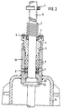
- a shut-off valve which is designed as a slide valve 12.
- the slide valve has a valve housing 14 in which a slide wedge, not shown here, is accommodated can be actuated via a spindle 13.
- the spindle 13 is guided in a cylindrical packing housing 19 of a sealing device 18, which is firmly connected to the valve housing 14.
- the cylindrical packing housing 19 is provided at its end in the valve housing 14 with a sealing seat 20 for receiving a spindle back seal 15, which takes effect when the slide is open (FIG. 3) and to which a threaded part 32 is fastened, which can be screwed into a threaded bore 31 is.
- the cylindrical packing housing 19 contains a guide bore 34 for the spindle 13, a bore 21 and a threaded bore 22 with an internal thread 26.
- the bore 21 is used to guide - in the example two - grooved metal rings 7 which are sealed against the by O-rings 23 Support the bore 21 or the spindle 13.
- the stuffing box 5 has a first extension part 25 which is provided with an external thread 10 which can be screwed into the cylindrical packing housing 10 via the internal thread 26 and serves to apply the required packing pressure to the graphite packing rings 6.
- a second extension part 27 of the stuffing box 5 has an extension bore 28 in which an axial bearing 3 is accommodated.
- the extension part 25 has a bevel 29, in which an O-ring 4 is accommodated, which is supported against the axial bearing 3.
- the axial bearing 3 is fixed by a retaining ring 9, which is held by fastening elements 16, in the example by screws, which engage in threaded bores 30 of the second extension part 27.
- a threaded hole 8 is provided in the cylindrical packing housing 19 in the area of the grooved metal rings 7 to accommodate a packing extrusion device, not shown here.
- a spring 2 is attached to the spindle 13 and is held by a height-adjustable locking ring 1. The latter can be fixed via a fastening element 17.
- the operation of the sealing device 18 is as follows:
- the locking ring 1 is fixed in accordance with FIG. 1 so that when the slide is closed, it exerts a precisely defined pressure on the O-ring 4, which has not been loaded until then, via the spring 2 and the axial bearing 3.
- the axial bearing 3 compensates for the radial forces and thus serves as wear protection.
- the design of the dynamically loaded sealing elements has been optimized.
- the grooved metal rings 7 with inserted O-rings 23 represent when changing the packing rings 6 in addition to the already known Spindle back seal 15 represents an additional sealing element.
- the metal rings 7 serve as an extrusion aid for the graphite packing rings 6.
- the contact pressure required for the graphite packing rings 6 is applied via the stuffing box 5 by screwing the external thread 10 into the internal thread 26.
- the threaded hole 8 is provided for the connection of a package extrusion device, not shown.
- a package extrusion device not shown.
- the retaining ring 9 serves to fix the only statically loaded O-ring 4 when the spindle is actuated.
- the spindle 13 With the help of the threaded part 32 arranged above the spindle back seal 15, which is screwed into the threaded bore 31, the spindle 13 can be locked with the slide open, so that the graphite packing rings 6 can be removed and installed undivided.
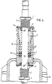
- the rear seal can be very similar the seal shown in the upper area of the drawing figures are carried out, as can be seen from Figure 4.
- the package housing 19 has at its lower end instead of the otherwise provided oblique sealing seat 20 with threaded bore 31 a circular cylindrical bore in which an annular body 3 'is located, which in the open position of the spindle 13 from a lower to the compression spring 2 analog Compression spring 2 'is applied.
- This additional annular body 3 'provided for the back seal presses an annular seal 4', which is preferably designed as an O-ring, into an inclined groove rising towards the center.
- the ring body 3 ' is secured by a retaining ring 9'.
- the described construction of the back seal corresponds in its basic structure to the sealing device which is effective at the upper end of the stuffing box 5. In the position according to FIG. 4, the rear seal is not effective, since this is an intermediate position. Rather, this back seal only becomes effective when the gate valve has moved into its open position.
- the stuffing box is fed in by twisting in a threaded bore.
- the sealing elements of the pack can also be acted upon by a stuffing box which can only be displaced in the axial direction and cannot be rotated and which is pressed against the pack via a compression spring which is effective in the axial direction.
Landscapes
- Engineering & Computer Science (AREA)
- General Engineering & Computer Science (AREA)
- Mechanical Engineering (AREA)
- Details Of Valves (AREA)
- Sealing Devices (AREA)
Applications Claiming Priority (2)
| Application Number | Priority Date | Filing Date | Title |
|---|---|---|---|
| DE4001233 | 1990-01-18 | ||
| DE4001233A DE4001233A1 (de) | 1990-01-18 | 1990-01-18 | Absperrarmatur |
Publications (2)
| Publication Number | Publication Date |
|---|---|
| EP0463155A1 EP0463155A1 (de) | 1992-01-02 |
| EP0463155B1 true EP0463155B1 (de) | 1993-12-15 |
Family
ID=6398251
Family Applications (1)
| Application Number | Title | Priority Date | Filing Date |
|---|---|---|---|
| EP91903713A Expired - Lifetime EP0463155B1 (de) | 1990-01-18 | 1991-01-17 | Absperrarmatur mit einer abdichtvorrichtung |
Country Status (4)
| Country | Link |
|---|---|
| EP (1) | EP0463155B1 (enExample) |
| JP (1) | JPH04504464A (enExample) |
| DE (2) | DE4001233A1 (enExample) |
| WO (1) | WO1991010855A1 (enExample) |
Families Citing this family (4)
| Publication number | Priority date | Publication date | Assignee | Title |
|---|---|---|---|---|
| EP0579569A1 (en) * | 1992-06-23 | 1994-01-19 | Purgadores De Condensado, S.L. | Self-protecting seat valve absolutely free of gaskets |
| JP5192285B2 (ja) * | 2008-05-20 | 2013-05-08 | 株式会社オーケーエム | バタフライ弁装置 |
| JP5689621B2 (ja) * | 2010-06-30 | 2015-03-25 | 株式会社キッツ | 高圧用回転弁の軸封構造 |
| CN119508507A (zh) * | 2024-11-14 | 2025-02-25 | 浙江中控流体技术有限公司 | 具有防卡防尘耐高温外置定位导向结构的蝶阀 |
Family Cites Families (9)
| Publication number | Priority date | Publication date | Assignee | Title |
|---|---|---|---|---|
| GB817426A (en) * | 1956-05-22 | 1959-07-29 | Alexander Samuel Volpin | Stem and stuffing box construction for non-rising stem gate valves |
| US2780233A (en) * | 1951-03-06 | 1957-02-05 | Alexander S Volpin | Through conduit gate valve |
| GB726795A (en) * | 1952-07-23 | 1955-03-23 | Magnesium Elektron Ltd | Improvements in or relating to valves |
| GB702736A (en) * | 1953-04-27 | 1954-01-20 | Alfred Jensen | Improvements in and relating to valves for atomizing fluids |
| DE1247103B (de) * | 1964-06-24 | 1967-08-10 | Philipp Kreis | Handbetaetigtes Schnellschlussventil |
| US3523551A (en) * | 1968-03-18 | 1970-08-11 | Milwaukee Faucets | Faucet construction |
| DE7001220U (de) * | 1970-01-14 | 1970-04-23 | Klein & Becker Ag | Vorrichtung zum ausbau von stopfbuchspackungen an armaturen |
| DE2412698A1 (de) * | 1974-03-16 | 1975-09-25 | Uhde Gmbh Friedrich | Stopfbuchspackungen fuer hochdruckventile |
| US4886241A (en) * | 1987-09-16 | 1989-12-12 | Fisher Controls International, Inc. | Valve stem packing containment for high pressure, high temperature |
-
1990
- 1990-01-18 DE DE4001233A patent/DE4001233A1/de active Granted
-
1991
- 1991-01-17 EP EP91903713A patent/EP0463155B1/de not_active Expired - Lifetime
- 1991-01-17 JP JP3503683A patent/JPH04504464A/ja active Pending
- 1991-01-17 WO PCT/EP1991/000074 patent/WO1991010855A1/de not_active Ceased
- 1991-01-17 DE DE91903713T patent/DE59100719D1/de not_active Expired - Fee Related
Also Published As
| Publication number | Publication date |
|---|---|
| DE4001233C2 (enExample) | 1992-12-10 |
| JPH04504464A (ja) | 1992-08-06 |
| WO1991010855A1 (de) | 1991-07-25 |
| DE59100719D1 (de) | 1994-01-27 |
| EP0463155A1 (de) | 1992-01-02 |
| DE4001233A1 (de) | 1991-08-01 |
Similar Documents
| Publication | Publication Date | Title |
|---|---|---|
| DE69118804T3 (de) | Gefederte Packungsstopfbuchse | |
| DE4001731C2 (de) | Stopfbuchs-Dichtungsanordnung | |
| DE3738571A1 (de) | Gelenkbolzenbaueinheit | |
| DE3218751A1 (de) | Dichtungseinrichtung | |
| DE69618803T2 (de) | Spindelabdichtung für kugelventile | |
| DE69113265T2 (de) | Schliessventilanordnung. | |
| DE68907710T2 (de) | Ventil mit nichtsteigender Spindel und Verfahren zum Ersetzen einer permanenten Dichtung. | |
| EP0733822A1 (de) | Mit Fluid gefüllte Zylinder-Kolbenstangen-Einheit, insbesondere Gasfeder | |
| DE69707237T2 (de) | Heizkörperventil | |
| DE69310469T2 (de) | Ventilanordung | |
| EP0463155B1 (de) | Absperrarmatur mit einer abdichtvorrichtung | |
| DE3002425A1 (de) | Druckbehaelterdichtung | |
| DE102019007550A1 (de) | Druckgasbehälter | |
| DE2332331C3 (de) | Kolbenventil mit geradem Durchgang und einem Propfen aus gummiartigem Werkstoff | |
| DE2851011A1 (de) | Mit ventilen ausgestattete kupplung fuer hochdruck-fluids | |
| DE29809529U1 (de) | Deckelloser Ventileinbau für Stopfbuchsventile | |
| DE4343562A1 (de) | Metallische Lamellendichtung für Klappenventile | |
| EP0411652B1 (de) | Schaltwellenabdichtung bei Armaturen | |
| DE3212982C2 (de) | Deckel für ein Pumpengehäuse | |
| EP0519582B1 (de) | Gasdichte Rohrverbindung | |
| DD267541A5 (de) | Schnellschluss-absperrschieber | |
| DE3116267C2 (de) | Abdichtungsvorrichtung für eine drehbar gelagerte Spindel eines Ventils | |
| DE19614982C1 (de) | Hochdruckleitungsanschluß | |
| DD213737A5 (de) | Ventil mit ventilgehaeuse | |
| DE4329342C1 (de) | Absperrhahn für Rohrleitungen, mit feuersicherer Federspaltabdichtung |
Legal Events
| Date | Code | Title | Description |
|---|---|---|---|
| PUAI | Public reference made under article 153(3) epc to a published international application that has entered the european phase |
Free format text: ORIGINAL CODE: 0009012 |
|
| AK | Designated contracting states |
Kind code of ref document: A1 Designated state(s): BE DE FR GB IT NL |
|
| 17P | Request for examination filed |
Effective date: 19911122 |
|
| 17Q | First examination report despatched |
Effective date: 19930429 |
|
| GRAA | (expected) grant |
Free format text: ORIGINAL CODE: 0009210 |
|
| AK | Designated contracting states |
Kind code of ref document: B1 Designated state(s): BE DE FR GB IT NL |
|
| PG25 | Lapsed in a contracting state [announced via postgrant information from national office to epo] |
Ref country code: IT Free format text: LAPSE BECAUSE OF FAILURE TO SUBMIT A TRANSLATION OF THE DESCRIPTION OR TO PAY THE FEE WITHIN THE PRESCRIBED TIME-LIMIT;WARNING: LAPSES OF ITALIAN PATENTS WITH EFFECTIVE DATE BEFORE 2007 MAY HAVE OCCURRED AT ANY TIME BEFORE 2007. THE CORRECT EFFECTIVE DATE MAY BE DIFFERENT FROM THE ONE RECORDED. Effective date: 19931215 Ref country code: GB Effective date: 19931215 |
|
| REF | Corresponds to: |
Ref document number: 59100719 Country of ref document: DE Date of ref document: 19940127 |
|
| ET | Fr: translation filed | ||
| GBV | Gb: ep patent (uk) treated as always having been void in accordance with gb section 77(7)/1977 [no translation filed] |
Effective date: 19931215 |
|
| PLBE | No opposition filed within time limit |
Free format text: ORIGINAL CODE: 0009261 |
|
| STAA | Information on the status of an ep patent application or granted ep patent |
Free format text: STATUS: NO OPPOSITION FILED WITHIN TIME LIMIT |
|
| PGFP | Annual fee paid to national office [announced via postgrant information from national office to epo] |
Ref country code: DE Payment date: 19941205 Year of fee payment: 5 |
|
| 26N | No opposition filed | ||
| PGFP | Annual fee paid to national office [announced via postgrant information from national office to epo] |
Ref country code: FR Payment date: 19950113 Year of fee payment: 5 |
|
| PGFP | Annual fee paid to national office [announced via postgrant information from national office to epo] |
Ref country code: BE Payment date: 19950118 Year of fee payment: 5 |
|
| PGFP | Annual fee paid to national office [announced via postgrant information from national office to epo] |
Ref country code: NL Payment date: 19950131 Year of fee payment: 5 |
|
| PG25 | Lapsed in a contracting state [announced via postgrant information from national office to epo] |
Ref country code: BE Effective date: 19960131 |
|
| BERE | Be: lapsed |
Owner name: EISENWERK HEINRICH SCHILLING G.M.B.H. & CO. Effective date: 19960131 |
|
| PG25 | Lapsed in a contracting state [announced via postgrant information from national office to epo] |
Ref country code: NL Effective date: 19960801 |
|
| PG25 | Lapsed in a contracting state [announced via postgrant information from national office to epo] |
Ref country code: FR Effective date: 19960930 |
|
| NLV4 | Nl: lapsed or anulled due to non-payment of the annual fee |
Effective date: 19960801 |
|
| PG25 | Lapsed in a contracting state [announced via postgrant information from national office to epo] |
Ref country code: DE Effective date: 19961001 |
|
| REG | Reference to a national code |
Ref country code: FR Ref legal event code: ST |