EP0463155B1 - Shut-off fitting with sealing device - Google Patents
Shut-off fitting with sealing device Download PDFInfo
- Publication number
- EP0463155B1 EP0463155B1 EP91903713A EP91903713A EP0463155B1 EP 0463155 B1 EP0463155 B1 EP 0463155B1 EP 91903713 A EP91903713 A EP 91903713A EP 91903713 A EP91903713 A EP 91903713A EP 0463155 B1 EP0463155 B1 EP 0463155B1
- Authority
- EP
- European Patent Office
- Prior art keywords
- shut
- sealing
- packing
- ring
- fitment according
- Prior art date
- Legal status (The legal status is an assumption and is not a legal conclusion. Google has not performed a legal analysis and makes no representation as to the accuracy of the status listed.)
- Expired - Lifetime
Links
Images


Classifications
-
- F—MECHANICAL ENGINEERING; LIGHTING; HEATING; WEAPONS; BLASTING
- F16—ENGINEERING ELEMENTS AND UNITS; GENERAL MEASURES FOR PRODUCING AND MAINTAINING EFFECTIVE FUNCTIONING OF MACHINES OR INSTALLATIONS; THERMAL INSULATION IN GENERAL
- F16K—VALVES; TAPS; COCKS; ACTUATING-FLOATS; DEVICES FOR VENTING OR AERATING
- F16K41/00—Spindle sealings
- F16K41/02—Spindle sealings with stuffing-box ; Sealing rings
Definitions
- the invention relates to a shut-off valve with a sealing device according to the preamble of claim 1.
- gland packing as seals for the spindles or shafts of shut-off valves. These seals are subject to high wear when the spindle or shaft is rotated, which is essentially caused by the dynamic loading of the sealing elements. Slider fittings with spindle back seals (cone, labyrinth) are also known which only take effect when the slider is fully open and then represent an additional static seal. This form of sealing essentially serves the purpose of being able to replace worn packing glands. Solutions with previously known stuffing box packings do not achieve the sealing effects that are required according to the legal provisions applicable in Germany today.
- a shut-off valve with a sealing packing known from US Pat. No. 2,780,233 also has the disadvantage that it has a comparatively large overall height.
- the use of only one seal packing serving as the main sealing element in the various operating positions cannot meet the legal regulations applicable in Germany even with this known solution.
- the fulfillment of the relevant tightness requirement is particularly not guaranteed when the seal packs have to be replaced, since a rear sealing element is completely missing.
- the structural design of the solution known from US Pat. No. 2,780,233 is comparatively complicated, so that a plurality of housing parts must be removed and installed when changing the seal pack.
- the object of the invention is a shut-off valve or to create a sealing device for a shut-off valve, which avoids the disadvantages of the known solutions and is characterized by the fulfillment of very high requirements for tightness.
- a fitting is intended in particular to meet the critical provisions of the German legal regulation, known under the short name "TAffy” and dated February 27, 1986.
- shut-off valve In the shut-off valve according to the invention, a design of the sealing area is provided which, due to a larger inner diameter, is not exposed to wear when the spindle or shaft rotates. The sealing elements are only subjected to pressure shortly before the valve closes.
- the majority of large fittings are in operation for a long time, either in the open or closed position Condition, since these are not control valves that change their operating states often.
- the periods between the operations of the large fittings are therefore very long, for example up to two years.
- the invention does justice to such static operation, which is far more than 99%, in that an additional static seal is provided in the sealing area both when the slide valve is closed and when it is in an intermediate position. This additional seal is not dynamically stressed during valve actuation and is therefore subject to practically no wear.
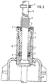
- a shut-off valve which is designed as a slide valve 12.
- the slide valve has a valve housing 14 in which a slide wedge, not shown here, is accommodated can be actuated via a spindle 13.
- the spindle 13 is guided in a cylindrical packing housing 19 of a sealing device 18, which is firmly connected to the valve housing 14.
- the cylindrical packing housing 19 is provided at its end in the valve housing 14 with a sealing seat 20 for receiving a spindle back seal 15, which takes effect when the slide is open (FIG. 3) and to which a threaded part 32 is fastened, which can be screwed into a threaded bore 31 is.
- the cylindrical packing housing 19 contains a guide bore 34 for the spindle 13, a bore 21 and a threaded bore 22 with an internal thread 26.
- the bore 21 is used to guide - in the example two - grooved metal rings 7 which are sealed against the by O-rings 23 Support the bore 21 or the spindle 13.
- the stuffing box 5 has a first extension part 25 which is provided with an external thread 10 which can be screwed into the cylindrical packing housing 10 via the internal thread 26 and serves to apply the required packing pressure to the graphite packing rings 6.
- a second extension part 27 of the stuffing box 5 has an extension bore 28 in which an axial bearing 3 is accommodated.
- the extension part 25 has a bevel 29, in which an O-ring 4 is accommodated, which is supported against the axial bearing 3.
- the axial bearing 3 is fixed by a retaining ring 9, which is held by fastening elements 16, in the example by screws, which engage in threaded bores 30 of the second extension part 27.
- a threaded hole 8 is provided in the cylindrical packing housing 19 in the area of the grooved metal rings 7 to accommodate a packing extrusion device, not shown here.
- a spring 2 is attached to the spindle 13 and is held by a height-adjustable locking ring 1. The latter can be fixed via a fastening element 17.
- the operation of the sealing device 18 is as follows:
- the locking ring 1 is fixed in accordance with FIG. 1 so that when the slide is closed, it exerts a precisely defined pressure on the O-ring 4, which has not been loaded until then, via the spring 2 and the axial bearing 3.
- the axial bearing 3 compensates for the radial forces and thus serves as wear protection.
- the design of the dynamically loaded sealing elements has been optimized.
- the grooved metal rings 7 with inserted O-rings 23 represent when changing the packing rings 6 in addition to the already known Spindle back seal 15 represents an additional sealing element.
- the metal rings 7 serve as an extrusion aid for the graphite packing rings 6.
- the contact pressure required for the graphite packing rings 6 is applied via the stuffing box 5 by screwing the external thread 10 into the internal thread 26.
- the threaded hole 8 is provided for the connection of a package extrusion device, not shown.
- a package extrusion device not shown.
- the retaining ring 9 serves to fix the only statically loaded O-ring 4 when the spindle is actuated.
- the spindle 13 With the help of the threaded part 32 arranged above the spindle back seal 15, which is screwed into the threaded bore 31, the spindle 13 can be locked with the slide open, so that the graphite packing rings 6 can be removed and installed undivided.
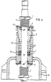
- the rear seal can be very similar the seal shown in the upper area of the drawing figures are carried out, as can be seen from Figure 4.
- the package housing 19 has at its lower end instead of the otherwise provided oblique sealing seat 20 with threaded bore 31 a circular cylindrical bore in which an annular body 3 'is located, which in the open position of the spindle 13 from a lower to the compression spring 2 analog Compression spring 2 'is applied.
- This additional annular body 3 'provided for the back seal presses an annular seal 4', which is preferably designed as an O-ring, into an inclined groove rising towards the center.
- the ring body 3 ' is secured by a retaining ring 9'.
- the described construction of the back seal corresponds in its basic structure to the sealing device which is effective at the upper end of the stuffing box 5. In the position according to FIG. 4, the rear seal is not effective, since this is an intermediate position. Rather, this back seal only becomes effective when the gate valve has moved into its open position.
- the stuffing box is fed in by twisting in a threaded bore.
- the sealing elements of the pack can also be acted upon by a stuffing box which can only be displaced in the axial direction and cannot be rotated and which is pressed against the pack via a compression spring which is effective in the axial direction.
Abstract
Description
Die Erfindung betrifft eine Absperrarmatur mit einer Abdichtvorrichtung nach dem Oberbegriff des Anspruchs 1.The invention relates to a shut-off valve with a sealing device according to the preamble of
Es ist allgemeiner Stand der Technik, Stopfbuchspackungen als Dichtungen für die Spindeln bzw. Wellen von Absperrarmaturen einzusetzen. Diese Dichtungen unterliegen beim Drehen der Spindel bzw. Welle einem hohem Verschleiß, der im wesentlichen durch die dynamische Beanspruchung der Dichtelemente verursacht wird. Es sind auch Schieberarmaturen mit Spindelrückdichtungen (Konus, Labyrinth) bekannt, die lediglich bei vollständig geöffnetem Schieber wirksam werden und dann eine zusätzliche statische Abdichtung darstellen. Diese Form der Abdichtung dient im wesentlichen dem Zweck, verschlissene Stopfbuchspackungen austauschen zu können. Lösungen mit bisher bekannten Stopfbuchspackungen erreichen nicht die Dichtungswirkungen, wie sie nach den heute in Deutschland geltenden gesetzlichen Bestimmungen gefordert werden.It is general state of the art to use gland packing as seals for the spindles or shafts of shut-off valves. These seals are subject to high wear when the spindle or shaft is rotated, which is essentially caused by the dynamic loading of the sealing elements. Slider fittings with spindle back seals (cone, labyrinth) are also known which only take effect when the slider is fully open and then represent an additional static seal. This form of sealing essentially serves the purpose of being able to replace worn packing glands. Solutions with previously known stuffing box packings do not achieve the sealing effects that are required according to the legal provisions applicable in Germany today.
Es ist weiterhin bereits bekannt, Spindel- und Wellenabdichtungen mit einem Faltenbalg auszurüsten. Diese Möglichkeit ist bisher nur bei kleineren Nennweiten (unter DN 200) angewendet worden. Die Faltenbalg-Ausführung erfordert eine Bauhöhe, die dem Drei- bis Vierfachen des Rohrleitungsdurchmessers entspricht und daher in vielen Fällen bereits wegen Platzmangels nicht einsetzbar ist. Ein weiterer Nachteil der Faltenbalg-Lösung besteht darin, daß bei defektem Faltenbalg ein Austauschen der kompletten Absperrarmatur erforderlich wird.It is also already known to equip spindle and shaft seals with a bellows. So far, this option has only been used for smaller nominal diameters (below DN 200). The bellows version requires a construction height that corresponds to three to four times the pipe diameter and therefore cannot be used in many cases due to lack of space. Another disadvantage of the bellows solution is that if the bellows is defective, the entire shut-off valve must be replaced.
Auch eine aus der US-PS 2,780,233 bekannte Absperrarmatur mit Dichtungspackung weist den Nachteil auf, daß sie eine vergleichsweise große Bauhöhe besitzt. Die Verwendung nur einer als Hauptdichtelement dienenden Dichtungspackung in den verschiedenen Betriebsstellungen kann auch bei dieser bekannten Lösung nicht die in Deutschland geltenden gesetzlichen Vorschriften erfüllen. Die Erfüllung der maßgeblichen Anforderung an die Dichtheit ist insbesondere auch nicht bei den erforderlichen Auswechslungen der Dichtungspackungen gewährleistet,da ein Rückdichtelement vollständig fehlt. Schließlich ist der konstruktive Aufbau der aus der US-PS 2,780,233 bekannten Lösung vergleichsweise kompliziert, so daß bei einem Dichtungspackungswechsel eine Mehrzahl von Gehäuseteilen aus- und eingebaut werden muß.A shut-off valve with a sealing packing known from US Pat. No. 2,780,233 also has the disadvantage that it has a comparatively large overall height. The use of only one seal packing serving as the main sealing element in the various operating positions cannot meet the legal regulations applicable in Germany even with this known solution. The fulfillment of the relevant tightness requirement is particularly not guaranteed when the seal packs have to be replaced, since a rear sealing element is completely missing. Finally, the structural design of the solution known from US Pat. No. 2,780,233 is comparatively complicated, so that a plurality of housing parts must be removed and installed when changing the seal pack.
Ausgehend von dem vorstehend genannten Stand der Technik liegt der Erfindung die Aufgabe zugrunde, eine Absperrarmatur bzw. eine Abdichtvorrichtung für eine Absperrarmatur zu schaffen, welche die Nachteile der bekannten Lösungen vermeidet und sich durch Erfüllung sehr hoher Anforderungen an die Dichtigkeit auszeichnet. Es sollen mit einer derartigen Armatur insbesondere die kritischen Bestimmungen der deutschen gesetzlichen Vorschrift erfüllt werden, die unter der Kurzbezeichnung "TA Luft" bekannt ist und vom 27.02.1986 datiert. Es soll eine besonders dichte Absperrarmatur, die kleine Bauhöhen ermöglicht, geschaffen werden und diese Armatur soll auch bei Rohrleiten mit größeren Nennweiten, also über DN 200, verwendbar und kostengünstig sein.Starting from the above-mentioned prior art, the object of the invention is a shut-off valve or to create a sealing device for a shut-off valve, which avoids the disadvantages of the known solutions and is characterized by the fulfillment of very high requirements for tightness. Such a fitting is intended in particular to meet the critical provisions of the German legal regulation, known under the short name "TA Luft" and dated February 27, 1986. A particularly tight shut-off valve, which enables small overall heights, is to be created, and this valve should also be usable and inexpensive for pipes with larger nominal diameters, that is to say over DN 200.
Die Lösung dieser Aufgabe erfolgt mit den Merkmalen des Kennzeichnungsteils von Anspruch 1. In den Unteransprüchen sind zweckmäßige Weiterbildungen der Absperrarmatur beschrieben.This object is achieved with the features of the characterizing part of
Bei der erfindungsgemäßen Absperrarmatur wird eine Ausgestaltung des Abdichtungsbereichs vorgesehen, der aufgrund eines größeren Innendurchmessers beim Drehen der Spindel bzw. Welle keinem Verschleiß ausgesetzt ist. Die Abdichtungselemente werden dabei erst kurz vor Beendigung des Schließvorgangs der Armatur auf Druck beansprucht.In the shut-off valve according to the invention, a design of the sealing area is provided which, due to a larger inner diameter, is not exposed to wear when the spindle or shaft rotates. The sealing elements are only subjected to pressure shortly before the valve closes.
Damit wird eine Optimierung der Gestaltung des Stopfbuchsbereichs erzielt, die einschlägigen gesetzlichen Bestimmungen sicher zu erfüllen, d.h. die Dichtung der Armatur gegenüber der äußeren Umwelt wird hierdurch zuverlässig gewährleistet.This optimizes the design of the stuffing box area so that it can safely comply with the relevant statutory provisions, i.e. the seal of the valve against the external environment is thereby reliably guaranteed.
Die Mehrzahl der Großarmaturen befinden sich im Betrieb jeweils längere Zeit entweder in geöffnetem oder geschlossenem Zustand, da es sich hierbei nicht um Regelarmaturen, die ihre Betriebszustände oft wechseln, handelt. Die Zeiträume zwischen den Bedienungsvorgängen der Großarmaturen sind folglich sehr lang, beispielsweise bis zu zwei Jahren. Einem solchen, zu weit über 99 % statischen Betrieb wird die Erfindung gerecht, indem im Abdichtungsbereich eine zusätzliche statische Abdichtung sowohl bei geschlossenem als auch bei in einer Zwischenstellung befindlichem Schieber vorgesehen ist. Diese zusätzliche Abdichtung wird bei Armaturbetätigungen nicht dynamisch beansprucht und unterliegt deshalb praktisch keinerlei Verschleiß.The majority of large fittings are in operation for a long time, either in the open or closed position Condition, since these are not control valves that change their operating states often. The periods between the operations of the large fittings are therefore very long, for example up to two years. The invention does justice to such static operation, which is far more than 99%, in that an additional static seal is provided in the sealing area both when the slide valve is closed and when it is in an intermediate position. This additional seal is not dynamically stressed during valve actuation and is therefore subject to practically no wear.
In der Zeichnung zeigen:
- Figur 1 -
- eine Schieberarmatur in geschlossener Stellung,
- Figur 2 -
- die Schieberarmatur nach
Figur 1 in einer Zwischenstellung, - Figur 3 -
- die Schieberarmatur gemäß
Figur 1 in geöffneter Stellung, - Figur 4 -
- eine alternative Ausführungsform
analog Figur 2.
- Figure 1 -
- a slide valve in the closed position,
- Figure 2 -
- the slide valve according to Figure 1 in an intermediate position,
- Figure 3 -
- the slide valve according to Figure 1 in the open position,
- Figure 4 -
- an alternative embodiment analogous to Figure 2.
In den Figuren 1 bis 3 ist eine Absperrarmatur dargestellt, die als Schieberarmatur 12 ausgebildet ist. Die Schieberarmatur weist ein Armaturengehäuse 14 auf, in dem ein hier nicht dargestellter Schieberkeil untergebracht ist, der über eine Spindel 13 betätigbar ist. Die Spindel 13 ist in einem zylindrischen Packungsgehäuse 19 einer Abdichtvorrichtung 18 geführt, die fest mit dem Armaturengehäuse 14 verbunden ist.In Figures 1 to 3, a shut-off valve is shown, which is designed as a
Das zylindrische Packungsgehäuse 19 ist an seinem im Armaturengehäuse 14 befindlichen Ende mit einem Dichtsitz 20 versehen zur Aufnahme einer Spindel-Rückdichtung 15, die bei geöffneter Schieberstellung (Figur 3) wirksam wird und an der ein Gewindeteil 32 befestigt ist, der in eine Gewindebohrung 31 einschraubbar ist. Das zylindrische Packungsgehäuse 19 enthält eine Führungsbohrung 34 für die Spindel 13, eine Aufbohrung 21 sowie eine Gewindebohrung 22 mit Innengewinde 26. Die Aufbohrung 21 dient zur Führung von - im Beispiel zwei - genuteten Metallringen 7, die sich über O-Ringe 23 dichtend gegen die Aufbohrung 21 bzw. die Spindel 13 abstützen. Weiterhin sind in der Aufbohrung 21 - siehe Figur 3 - Graphit-Packungsringe 6 untergebracht, die den genuteten Metallringen 7 aufsitzen und gegen die eine Stopfbuchse 5 anpreßbar ist, deren Bohrung 33 sich über O-Ringe 24 gegen die Spindel 13 und deren Dichtsitz 11 sich über O-Ringe 24 gegen die Aufbohrung 21 abstützen.The
Die Stopfbuchse 5 weist einen ersten Erweiterungsteil 25 auf, der mit einem Außengewinde 10 versehen ist, das über das Innengewinde 26 in das zylindrische Packungsgehäuse 10 einschraubbar ist und zum Aufbringen der erforderlichen Packungspressung auf die Graphit-Packungsringe 6 dient. Ein zweiter Erweiterungsteil 27 der Stopfbuchse 5 weist eine Erweiterungsbohrung 28 auf,in der ein Achsiallager 3 untergebracht ist. Der Erweiterungsteil 25 hat eine Abschrägung 29, in der ein O-Ring 4 untergebracht ist, der sich gegen das Achsiallager 3 abstützt.The
Das Achsiallager 3 wird durch einen Rückhaltering 9 fixiert, der über Befestigungselemente 16, im Beispiel durch Schrauben, gehalten wird, die in Gewindebohrungen 30 des zweiten Erweiterungsteiles 27 eingreifen.The axial bearing 3 is fixed by a
Zur Aufnahme einer hier nicht dargestellten Packungsauspreß-Vorrichtung ist im Bereich der genuteten Metallringe 7 ein Gewindeloch 8 im zylindrischen Packungsgehäuse 19 vorgesehen.A threaded
Auf die Spindel 13 ist eine Feder 2 aufgesteckt, die durch einen höhenverstellbaren Feststellring 1 gehalten wird. Letzterer ist über ein Befestigungselement 17 fixierbar.A
Die Wirkungsweise der Abdichtvorrichtung 18 ist folgende:The operation of the
Schieber geschlossen:Slider closed:
Der Feststellring 1 ist gemäß Figur 1 so fixiert, daß er beim Schließen des Schiebers über die Feder 2 und das Achsiallager 3 einen genau definierten Druck auf den bis zu diesem Zeitpunkt unbelasteten O-Ring 4 ausübt. Das Achsiallager 3 kompensiert dabei die aufretenden Radialkräfte und dient somit als Verschleißschutz. Im Zusammenhang mit dieser statischen Dichtung ist die Gestaltung der dynamisch belasteten Dichtungselemente optimiert worden. Die genuteten Metallringe 7 mit eingesetzten O-Ringen 23 stellen beim Wechseln der Packungsringe 6 neben der bereits für sich bekannten Spindel-Rückdichtung 15 ein zusätzliches Abdichtungselement dar. Außerdem dienen die Metallringe 7 als Auspreßhilfe für die Graphit-Packungsringe 6. Der für die Graphit-Packungsringe 6 erforderliche Anpreßdruck wird über die Stopfbuchse 5 durch Eindrehen des Außengewindes 10 in das Innengewinde 26 aufgebracht.The
Das Gewindeloch 8 ist für den Anschluß einer nicht dargestellten Packungsauspreß-Vorrichtung vorgesehen. Bei Anwendung dieser Vorrichtung werden Spindel- und Dichtungsflächen-Beschädigungen vermieden, die ansonsten beim Entfernen der Packungsringe 6 mittels Packungszieher (-Nadel) häufig auftreten. Der Rückhaltering 9 dient der Fixierung des nur statisch belasteten O-Ringes 4 bei Spindelbetätigung.The threaded
Mit Hilfe des oberhalb der Spindel-Rückdichtung 15 angeordneten Gewindeteils 32, das in die Gewindebohrung 31 eingedreht wird, kann die Spindel 13 bei geöffnetem Schieber arretiert werden,so daß die Graphit-Packungsringe 6 ungeteilt aus- und eingebaut werden können.With the help of the threaded
Schieber in Zwischenstellung:Slider in intermediate position:
Bei dieser Stellung entsprechend Figur 2, die vergleichsweise selten notwendig ist, wird gemäß dem geänderten Öffnungsverhältnis der Feststellring 1 höher auf der Spindel 13 neu fixiert.In this position according to FIG. 2, which is comparatively rarely necessary, the
Statt der in den Zeichnungsfiguren 1 bis 3 dargestellten und vorstehend beschriebenen Rückdichtung mit Dichtsitz 20 und Spindelrückdichtung 15 kann die Rückdichtung sehr ähnlich der im oberen Bereich der Zeichnungsfiguren dargestellten Dichtung ausgeführt werden, wie dies aus Figur 4 ersichtlich ist. Bei dieser alternativen Ausführungsform besitzt das Päckungsgehäuse 19 an seinem unteren Ende statt des dort sonst vorgesehenen schräg verlaufenden Dichtsitzes 20 mit Gewindebohrung 31 eine kreiszylindrische Bohrung, in der ein Ringkörper 3' liegt, der in der Öffnungsstellung der Spindel 13 von einer zur Druckfeder 2 analogen unteren Druckfeder 2' beaufschlagt wird. Dieser für die Rückdichtung vorgesehene zusätzliche Ringkörper 3' drückt eine vorzugsweise als O-Ring ausgebildete Ringdichtung 4' in eine zum Zentrum ansteigende Schrägnut. Der Ringkörper 3' ist über einen Rückhaltering 9' gesichert. Die beschriebene Konstruktion der Rückdichtung entspricht in ihrem grundsätzlichen Aufbau der Dichtungseinrichtung, die am oberen Ende der Stopfbuchse 5 wirksam ist. In der Stellung gemäß Figur 4 ist die Rückdichtung nicht wirksam, da es sich hier um eine Zwischenstellung handelt. Diese Rückdichtung wird vielmehr erst wirksam, wenn der Absperrschieber in seine Öffnungsstellung gefahren ist.Instead of the rear seal with sealing
In der dargestellten Ausführungsform erfolgt die Zustellung der Stopfbuchse über ein Verdrehen in einer Gewindebohrung. Statt dessen können die Dichtelemente der Packung auch durch eine lediglich in Achsrichtung verschiebbare, nicht verdrehbare Stopfbuchse beaufschlagt werden, welche über eine in Achsrichtung wirksame Druckfeder gegen die Packung gedrückt wird.In the embodiment shown, the stuffing box is fed in by twisting in a threaded bore. Instead, the sealing elements of the pack can also be acted upon by a stuffing box which can only be displaced in the axial direction and cannot be rotated and which is pressed against the pack via a compression spring which is effective in the axial direction.
Claims (12)
- Shut-off fitment with a sealing device (18) comprising a packing casing (19) and stuffing box gland (5) for the operating element (13) of the shut-off element, wherein the packing casing (19) has a bore (21) for a sealing packing (6) which serves as the main sealing element, and a guide bore (34) is provided for the operating element (13),
characterised in thata) the sealing packing has at least one grooved metal ring (7) with elastic sealing rings (23) opposite the operating element (13) and the bore (21),b) the stuffing box gland (5) has an incline (29) dropping towards the centre as a seat for an elastic sealing ring (4) which is biased in the longitudinal axial direction of the operating element (13) by the force of a spring (2). - Shut-off fitment according to claim 1,
characterised in that it has a return sealing device (15, 20; 4', 3', 2', 1'). - Shut-off fitment according to claim 1 or 2
characterised in that the ring body (3) is biased by a compression spring (2) enclosing the operating element (13) and designed to adjoin the ring body (3) on one side and a stop (1) of the operating element (13) on the other. - Shut-off fitment according to claim 3
characterised in that the stop (1) is formed by a ring (1) fixed on the operating element (13). - Shut-off fitment according to one or more of claims 1 to 4 characterised in that the return seal likewise has a ring body (3') which is biased by the force of a spring (2') and likewise presses an elastic ring seal (4') into an inclined groove (29') which falls towards the centre and which is provided on the side of the packing casing (19) facing the shut-off element , wherein the ring seal (4') seals between the inclined groove (29') of the packing casing (19) and the circumference of the operating element (13).
- Shut-off fitment according to one or more of claims 1 to 5 characterised in that the ring body (3) is guided in a surrounding bore (28) of the stuffing box gland (5) and is held on same by means of a screwed-on retaining element which engages over same.
- Shut-off fitment according to claim 6
characterised in that the retaining element is a retaining ring (9). - Shut-off fitment according to one or more of claims 1 to 7 characterised in that the ring body (3) is an axial bearing.
- Shut-off fitment according to one or more of claims 1 to 8 characterised in that graphite packing rings (6) are used as the sealing elements of the sealing packing.
- Shut-off fitment according to one or more of claims 1 to 9 characterised in that the sealing elements (6;7) can be connected by a threaded hole (8) to a packing ejector device.
- Shut-off fitment according to one or more of claims 1 to 10 characterised in that the stuffing box gland (5) is pretensioned against the sealing elements (6;7) by a compression spring element acting in the longitudinal axial direction.
- Shut-off fitment according to one or more of claims 1 to 11 characterised in that the sealing rings (4; 23; 24) are O-rings.
Applications Claiming Priority (2)
| Application Number | Priority Date | Filing Date | Title |
|---|---|---|---|
| DE4001233A DE4001233A1 (en) | 1990-01-18 | 1990-01-18 | SHUT-OFF ARMATURE |
| DE4001233 | 1990-01-18 |
Publications (2)
| Publication Number | Publication Date |
|---|---|
| EP0463155A1 EP0463155A1 (en) | 1992-01-02 |
| EP0463155B1 true EP0463155B1 (en) | 1993-12-15 |
Family
ID=6398251
Family Applications (1)
| Application Number | Title | Priority Date | Filing Date |
|---|---|---|---|
| EP91903713A Expired - Lifetime EP0463155B1 (en) | 1990-01-18 | 1991-01-17 | Shut-off fitting with sealing device |
Country Status (4)
| Country | Link |
|---|---|
| EP (1) | EP0463155B1 (en) |
| JP (1) | JPH04504464A (en) |
| DE (2) | DE4001233A1 (en) |
| WO (1) | WO1991010855A1 (en) |
Families Citing this family (3)
| Publication number | Priority date | Publication date | Assignee | Title |
|---|---|---|---|---|
| EP0579569A1 (en) * | 1992-06-23 | 1994-01-19 | Purgadores De Condensado, S.L. | Self-protecting seat valve absolutely free of gaskets |
| JP5192285B2 (en) * | 2008-05-20 | 2013-05-08 | 株式会社オーケーエム | Butterfly valve device |
| JP5689621B2 (en) * | 2010-06-30 | 2015-03-25 | 株式会社キッツ | Shaft seal structure of rotary valve for high pressure |
Family Cites Families (9)
| Publication number | Priority date | Publication date | Assignee | Title |
|---|---|---|---|---|
| GB817426A (en) * | 1956-05-22 | 1959-07-29 | Alexander Samuel Volpin | Stem and stuffing box construction for non-rising stem gate valves |
| US2780233A (en) * | 1951-03-06 | 1957-02-05 | Alexander S Volpin | Through conduit gate valve |
| GB726795A (en) * | 1952-07-23 | 1955-03-23 | Magnesium Elektron Ltd | Improvements in or relating to valves |
| GB702736A (en) * | 1953-04-27 | 1954-01-20 | Alfred Jensen | Improvements in and relating to valves for atomizing fluids |
| DE1247103B (en) * | 1964-06-24 | 1967-08-10 | Philipp Kreis | Manually operated quick-closing valve |
| US3523551A (en) * | 1968-03-18 | 1970-08-11 | Milwaukee Faucets | Faucet construction |
| DE7001220U (en) * | 1970-01-14 | 1970-04-23 | Klein & Becker Ag | DEVICE FOR REMOVING Gland Packings from FITTINGS |
| DE2412698A1 (en) * | 1974-03-16 | 1975-09-25 | Uhde Gmbh Friedrich | PACKING BOX FOR HIGH PRESSURE VALVES |
| US4886241A (en) * | 1987-09-16 | 1989-12-12 | Fisher Controls International, Inc. | Valve stem packing containment for high pressure, high temperature |
-
1990
- 1990-01-18 DE DE4001233A patent/DE4001233A1/en active Granted
-
1991
- 1991-01-17 EP EP91903713A patent/EP0463155B1/en not_active Expired - Lifetime
- 1991-01-17 WO PCT/EP1991/000074 patent/WO1991010855A1/en active IP Right Grant
- 1991-01-17 JP JP3503683A patent/JPH04504464A/en active Pending
- 1991-01-17 DE DE91903713T patent/DE59100719D1/en not_active Expired - Fee Related
Also Published As
| Publication number | Publication date |
|---|---|
| JPH04504464A (en) | 1992-08-06 |
| WO1991010855A1 (en) | 1991-07-25 |
| DE4001233A1 (en) | 1991-08-01 |
| EP0463155A1 (en) | 1992-01-02 |
| DE59100719D1 (en) | 1994-01-27 |
| DE4001233C2 (en) | 1992-12-10 |
Similar Documents
| Publication | Publication Date | Title |
|---|---|---|
| DE3153338C2 (en) | Actuating device for a valve | |
| EP0173115B1 (en) | Solenoid valve for vacuum application | |
| DE3738571A1 (en) | JOINT BOLT UNIT | |
| DE2943327C2 (en) | Sealing device for a slide spindle | |
| DE3218751A1 (en) | SEALING DEVICE | |
| DE4001731C2 (en) | Gland packing arrangement | |
| EP0733822A1 (en) | Cylinder-piston unit filled with a fluid,especially a gasspring | |
| DE1525702A1 (en) | Seal for a rotating shaft | |
| EP0463155B1 (en) | Shut-off fitting with sealing device | |
| DE3002425A1 (en) | PRESSURE TANK SEAL | |
| EP0544997B1 (en) | Device for holding a stopper and stopper | |
| DE2332331C3 (en) | Piston valve with straight passage and a plug made of rubber-like material | |
| DE2851011A1 (en) | VALVED COUPLING FOR HIGH PRESSURE FLUIDS | |
| EP0663549A1 (en) | Metallic seal for butterfly valves | |
| EP0411652B1 (en) | Valve spindle sealing | |
| DE102019007550A1 (en) | Pressurized gas container | |
| DE3212982C2 (en) | Cover for a pump housing | |
| DE3303877C2 (en) | Single piston valve | |
| EP0519582B1 (en) | Gas-tight pipe coupling | |
| DE2646781C3 (en) | Sealing system for switch shafts | |
| DE3116267C2 (en) | Sealing device for a rotatably mounted spindle of a valve | |
| DE19614982C1 (en) | High pressure line connection | |
| DD213737A5 (en) | VALVE WITH VALVE HOUSING | |
| DE4329342C1 (en) | Shut-off cock for pipe conduits, with a fire-proof spring seal | |
| EP0318737A2 (en) | Spherical cock |
Legal Events
| Date | Code | Title | Description |
|---|---|---|---|
| PUAI | Public reference made under article 153(3) epc to a published international application that has entered the european phase |
Free format text: ORIGINAL CODE: 0009012 |
|
| AK | Designated contracting states |
Kind code of ref document: A1 Designated state(s): BE DE FR GB IT NL |
|
| 17P | Request for examination filed |
Effective date: 19911122 |
|
| 17Q | First examination report despatched |
Effective date: 19930429 |
|
| GRAA | (expected) grant |
Free format text: ORIGINAL CODE: 0009210 |
|
| AK | Designated contracting states |
Kind code of ref document: B1 Designated state(s): BE DE FR GB IT NL |
|
| PG25 | Lapsed in a contracting state [announced via postgrant information from national office to epo] |
Ref country code: IT Free format text: LAPSE BECAUSE OF FAILURE TO SUBMIT A TRANSLATION OF THE DESCRIPTION OR TO PAY THE FEE WITHIN THE PRESCRIBED TIME-LIMIT;WARNING: LAPSES OF ITALIAN PATENTS WITH EFFECTIVE DATE BEFORE 2007 MAY HAVE OCCURRED AT ANY TIME BEFORE 2007. THE CORRECT EFFECTIVE DATE MAY BE DIFFERENT FROM THE ONE RECORDED. Effective date: 19931215 Ref country code: GB Effective date: 19931215 |
|
| REF | Corresponds to: |
Ref document number: 59100719 Country of ref document: DE Date of ref document: 19940127 |
|
| ET | Fr: translation filed | ||
| GBV | Gb: ep patent (uk) treated as always having been void in accordance with gb section 77(7)/1977 [no translation filed] |
Effective date: 19931215 |
|
| PLBE | No opposition filed within time limit |
Free format text: ORIGINAL CODE: 0009261 |
|
| STAA | Information on the status of an ep patent application or granted ep patent |
Free format text: STATUS: NO OPPOSITION FILED WITHIN TIME LIMIT |
|
| PGFP | Annual fee paid to national office [announced via postgrant information from national office to epo] |
Ref country code: DE Payment date: 19941205 Year of fee payment: 5 |
|
| 26N | No opposition filed | ||
| PGFP | Annual fee paid to national office [announced via postgrant information from national office to epo] |
Ref country code: FR Payment date: 19950113 Year of fee payment: 5 |
|
| PGFP | Annual fee paid to national office [announced via postgrant information from national office to epo] |
Ref country code: BE Payment date: 19950118 Year of fee payment: 5 |
|
| PGFP | Annual fee paid to national office [announced via postgrant information from national office to epo] |
Ref country code: NL Payment date: 19950131 Year of fee payment: 5 |
|
| PG25 | Lapsed in a contracting state [announced via postgrant information from national office to epo] |
Ref country code: BE Effective date: 19960131 |
|
| BERE | Be: lapsed |
Owner name: EISENWERK HEINRICH SCHILLING G.M.B.H. & CO. Effective date: 19960131 |
|
| PG25 | Lapsed in a contracting state [announced via postgrant information from national office to epo] |
Ref country code: NL Effective date: 19960801 |
|
| PG25 | Lapsed in a contracting state [announced via postgrant information from national office to epo] |
Ref country code: FR Effective date: 19960930 |
|
| NLV4 | Nl: lapsed or anulled due to non-payment of the annual fee |
Effective date: 19960801 |
|
| PG25 | Lapsed in a contracting state [announced via postgrant information from national office to epo] |
Ref country code: DE Effective date: 19961001 |
|
| REG | Reference to a national code |
Ref country code: FR Ref legal event code: ST |