EP0459728A2 - Reifenaufbautrommel - Google Patents
Reifenaufbautrommel Download PDFInfo
- Publication number
- EP0459728A2 EP0459728A2 EP91304754A EP91304754A EP0459728A2 EP 0459728 A2 EP0459728 A2 EP 0459728A2 EP 91304754 A EP91304754 A EP 91304754A EP 91304754 A EP91304754 A EP 91304754A EP 0459728 A2 EP0459728 A2 EP 0459728A2
- Authority
- EP
- European Patent Office
- Prior art keywords
- stitching
- supports
- forming drum
- tire
- sleeves
- Prior art date
- Legal status (The legal status is an assumption and is not a legal conclusion. Google has not performed a legal analysis and makes no representation as to the accuracy of the status listed.)
- Ceased
Links
Images


Classifications
-
- B—PERFORMING OPERATIONS; TRANSPORTING
- B29—WORKING OF PLASTICS; WORKING OF SUBSTANCES IN A PLASTIC STATE IN GENERAL
- B29D—PRODUCING PARTICULAR ARTICLES FROM PLASTICS OR FROM SUBSTANCES IN A PLASTIC STATE
- B29D30/00—Producing pneumatic or solid tyres or parts thereof
- B29D30/06—Pneumatic tyres or parts thereof (e.g. produced by casting, moulding, compression moulding, injection moulding, centrifugal casting)
- B29D30/08—Building tyres
- B29D30/20—Building tyres by the flat-tyre method, i.e. building on cylindrical drums
- B29D30/24—Drums
- B29D30/244—Drums for manufacturing substantially cylindrical tyre components with cores or beads, e.g. carcasses
- B29D30/245—Drums for the single stage building process, i.e. the building-up of the cylindrical carcass and the toroidal expansion of it are realised on the same drum
-
- B—PERFORMING OPERATIONS; TRANSPORTING
- B29—WORKING OF PLASTICS; WORKING OF SUBSTANCES IN A PLASTIC STATE IN GENERAL
- B29D—PRODUCING PARTICULAR ARTICLES FROM PLASTICS OR FROM SUBSTANCES IN A PLASTIC STATE
- B29D30/00—Producing pneumatic or solid tyres or parts thereof
- B29D30/06—Pneumatic tyres or parts thereof (e.g. produced by casting, moulding, compression moulding, injection moulding, centrifugal casting)
- B29D30/08—Building tyres
- B29D30/20—Building tyres by the flat-tyre method, i.e. building on cylindrical drums
- B29D30/32—Fitting the bead-rings or bead-cores; Folding the textile layers around the rings or cores
- B29D2030/3214—Locking the beads on the drum; details of the drum in the bead locking areas, e.g. drum shoulders
-
- B—PERFORMING OPERATIONS; TRANSPORTING
- B29—WORKING OF PLASTICS; WORKING OF SUBSTANCES IN A PLASTIC STATE IN GENERAL
- B29D—PRODUCING PARTICULAR ARTICLES FROM PLASTICS OR FROM SUBSTANCES IN A PLASTIC STATE
- B29D30/00—Producing pneumatic or solid tyres or parts thereof
- B29D30/06—Pneumatic tyres or parts thereof (e.g. produced by casting, moulding, compression moulding, injection moulding, centrifugal casting)
- B29D30/08—Building tyres
- B29D30/20—Building tyres by the flat-tyre method, i.e. building on cylindrical drums
- B29D30/32—Fitting the bead-rings or bead-cores; Folding the textile layers around the rings or cores
- B29D2030/3221—Folding over means, e.g. bladders or rigid arms
- B29D2030/3228—Folding over means, e.g. bladders or rigid arms using one bladder acting on each side of the drum
-
- B—PERFORMING OPERATIONS; TRANSPORTING
- B29—WORKING OF PLASTICS; WORKING OF SUBSTANCES IN A PLASTIC STATE IN GENERAL
- B29D—PRODUCING PARTICULAR ARTICLES FROM PLASTICS OR FROM SUBSTANCES IN A PLASTIC STATE
- B29D30/00—Producing pneumatic or solid tyres or parts thereof
- B29D30/06—Pneumatic tyres or parts thereof (e.g. produced by casting, moulding, compression moulding, injection moulding, centrifugal casting)
- B29D30/08—Building tyres
- B29D30/20—Building tyres by the flat-tyre method, i.e. building on cylindrical drums
- B29D30/32—Fitting the bead-rings or bead-cores; Folding the textile layers around the rings or cores
- B29D2030/3221—Folding over means, e.g. bladders or rigid arms
- B29D2030/3257—Folding over means, e.g. bladders or rigid arms using pressing rollers
Definitions
- This invention relates to a tire forming drum suitable for use in so-called single stage forming wherein a green tire is completely produced on one forming drum, and more particularly to a tire forming drum capable of sufficiently preventing residual air in tire bead portions.
- a conventional tire forming drum of this kind generally includes a pair of bead lock means, shaping means and ply turning-up means for turning up a ply of a tire.
- bead cores b are arranged on the outer side of an inner lining (a) such as an inner liner or a carcass ply.
- inner lining such as an inner liner or a carcass ply.
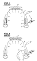
- a crown portion of the inner lining (a) is joined with the inner circumferential surface of a belt-tread band d by movement of the pair of bead lock means toward each other, while the configuration of the tire is conditioned. Thereafter, both side edges of the inner lining (a) are folded thereupon or turned up as shown in Fig. 1 by means of ply turning-up means (not shown). Moreover, stitcher rolls e are urged against the tire so that the air existing between the laminated layers of the tire is expelled therefrom and the layers are sufficiently joined with each other.
- shoulder bladders f are used to urge inner circumferential surfaces of bead portions toward stitcher rolls as shown in Fig. 2.
- the shoulder bladders f could not still sufficiently support the urging force of the stitcher rolls e.
- the shoulder bladders f could not be brought into sufficiently close contact with the bead portions, particularly, the radially inner ends thereof. Accordingly, high stitching effect could not be substantially accomplished in this prior proposal.
- each of said stitching supports is composed of a rigid lever having one end pivotally connected to a housing of one of the bead lock means and the other end provided with a close contact portion to be brought into close contact with an inner circumferential surface of one bead portion of a tire being formed, and actuating means for each of the stitching supports is composed of a rigid link having one end pivotally connected to a mid portion of the stitching support and the other end pivotally connected to one of sleeves movable in axial directions of the forming drum, thereby enabling the stitching supports to expand by movements of the sleeves and the bead lock means arranged on both sides toward each other.
- the pair of bead lock means are moved toward each other.
- the stitching supports are arranged associated with the respective bead lock means and spaced from each other in axial directions of the drum, while actuating means for the respective stitching supports are pivotally connected to sleeves movable in the axial directions of the drum.
- the sleeves abut against each other directly or indirectly through a spacer.
- the actuating means are rotated radially outwardly of the drum so that the stitching supports are progressively moved into their expanded positions.
- both the bead lock means have arrived at the approached limit positions, the stitching supports are completely in close contact with inner circumferential surfaces of the bead portions of a tire being formed with close contact portions provided on the stitching supports. Therefore, the bead portions are prevented from deforming inwardly in tire width directions in a reliable manner with the aid of the rigidity of the stitching supports themselves.
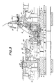
- Fig. 3 is a partial longitudinal sectional view illustrating one embodiment of the tire forming drum according to the present invention, wherein the lower half of the forming drum is not shown because it is quite the same as the upper half of the forming drum.
- the right half shows one stitching support in an expanded state, while the left half illustrates its collapsed state.
- Reference numeral 1 denotes a screw shaft having, on both sides of its center, male screw portions 1a whose turns are in reverse directions.
- Female screw members 2 are threadedly engaged on the male screw portions 1a, respectively.
- To the female screw members 2 are fixed shifters 5, respectively, extending through a hollow cylinder member 3 arranged around the screw shaft 1 and causing bead lock means 4 and other means (not shown) to be displaced.
- both the female screw members 2 are moved toward and away from each other, and therefore the shifters 5 can move in slots formed in the hollow cylinder member 3 together with the bead lock means and other means in response to the movements of the female screw members 2.
- the pair of bead lock means 4 are movable toward and away from each other by means of the shifters in this manner.
- Each of the bead lock means 4 is composed of a plurality of bead lock sliders 6 circumferentially arranged and radially movable to expand and contract diameters of an imaginary circle formed by themselves, and a housing 7 permitting the bead lock sliders 6 to move radially inwardly and outwardly.
- each of the bead lock sliders 6 of the bead lock means 4 can be accomplished in the following manner.
- a rocking member 8 is provided whose intermediate portion is pivotally supported on a part integral with the housing 7 and whose one end passes through the housing and is engaged with a pin 9 provided on the bead lock slider 6 and the other end is engaged with a piston 10 slidably movable in axial directions of the hollow cylinder member 3.
- the pistons 10 are slidably moved between the retracted state as shown in the left half of the drawing, Fig. 3 and the advanced state as shown in the right half in the drawing.
- the rocking members 8 operate as bell cranks to convert the axial displacements of the pistons 10 to radial displacements of the bead lock sliders 6.
- reference numeral 11 illustrates a plurality of stitching supports circumferentially arranged between the pair of bead lock means.
- each of the stitching supports 11 comprises a rigid lever 13 having one end pivotally connected to the housing 7 through a bracket 12 and the other end provided with a stitching plate or close contact portion 13a.
- the stitching plate 13a has a contour commensurate with an inner shape of a tire to be formed and adapted to be brought into close contact with an inner circumferential surface of a bead portion of the tire.
- the stitch plate or close contact portion 13a at the free end of the rigid lever 13 can of course be appropriately modified in accordance with sizes and shapes of tires to be formed.
- Each of actuating means 14 for moving the stitching supports 11 is composed of rigid links 17 and causes the stitching supports 11 to expand and collapse.
- Each of the rigid links 17 has one end pivotally connected to the mid portion of the stitching support 11 and the other end pivotally connected through a bracket 16 to a sleeve 15 movable in axial directions of the hollow cylinder member 3.
- the rigid links 17 are pivotally rotatable in radial planes about the pivoted points to the sleeve 15.
- the positional relation between the stitching support 11 and the actuating means 14 is so selected that the pivoted point between the support 11 and the means 14 is located radially outwardly of a straight line segment connecting the pivoted point of the stitching support 11 to the housing 7 and the pivoted point of the rigid link 17 of the actuating means 14 to the sleeve 15.
- This positional relation between the stitching support 11 and the actuating means 14 ensures that when the housing 7 is moved toward the sleeve 15, the actuating means 14 and hence the stitching supports 11 are rotated to their expanded positions.
- the expanding rotation of the actuating means or the movement of the housings 7 toward the sleeves 15 is accomplished by an abutment of the sleeves 15 provided associated with the respective bead lock means 4.
- the abutment of the sleeves 15 is caused by the movement of the bead lock means 4 toward each other, while the optimum timing of the abutment depends upon sizes of tires to be formed.
- a spacer 18 having a required thickness is attached to one of the sleeves 15 and both the sleeves 15 are caused to abut against each other through the spacer 18 therebetween, thereby adjusting the timing of the actuating means for expanding the stitching support. Consequently, if a size of a tire does not require the spacer, the forming of a tire can be carried out without providing it.
- the spacer 18 may be attached to the center of the hollow cylinder member 3 instead of fixing it to any one of the sleeve 15.
- the following measures may be employed in order to smoothly perform the expanding rotation and collapsing movement of the stitching supports 11 and the actuating means 14.
- Springs 19 are interposed between the housings 7 and the sleeves 15 so that the housing 7 and the sleeves 15 are forced away from each other.
- Springs 20 and 21 are provided on the stitching supports 11 and the actuating means 14 to force them into their collapsing directions, respectively.
- each of the sleeves 15 is provided in the inner circumferential surface with at least one slider 22 which is adapted to be fitted in a guide groove (the slot for permitting of the shifter moving in this embodiment) formed in and extending in the axial direction of the hollow cylinder member 3, thereby permitting the axial movement of the sleeve 15 but restraining any rotational movement of the sleeve 15 about its axis.
- a guide groove the slot for permitting of the shifter moving in this embodiment
- reference numeral 23 illustrates a bladder as means for turning up plies.
- This bladder 23 is folded upon itself on the inner side of the bead portion supporting surfaces of the bead lock sliders 6 into the form of an annular bag as a whole.
- This tire forming drum further includes a plurality of pressurized air jetting openings (not shown) formed in the hollow cylinder member 3 between both the bead lock means and serving as shaping means.
- a pair of bead cores 32 and a pair of bead fillers 33 spaced predetermined distances on the right and left sides are set mainly on the outer side of a carcass 31 wound around the forming drum.
- the rocking members 8 are then actuated so as to move the bead lock sliders 6 radially outwardly to increase diameters of their imaginary circles.
- the bead cores 32 together with the carcass 31 are held by the bead lock sliders 6 as shown in phantom lines in Fig. 4a.
- the carcass 31 is caused to expand radially outwardly and a crown portion of the carcass 31 is joined with the inner circumferential surface of a belt-tread band 34 previously set at a predetermined position on the outer side of the carcass.
- the bladders 23 as ply turning up means are expanded by means of pressurized air at a predetermined pressure to fold or turn up the side edges of the ply 31 to predetermined positions over whole the circumference of the tire as shown in the left half of Fig. 4b.
- the pressurized air in the bladders 23 is exhausted so that they are flattened as shown in the right of Fig. 4b.
- stitcher rolls 35 are urged with predetermined forces mainly against outer surfaces of the bead portions and the belt-tread band 34.
- the stitcher rolls 35 are rotated by frictional forces between the rolls 35 and the tire and moved along the outer surfaces of the bead portions and the band 34. Consequently, the laminated layers are joined with each other and the air interposed between the respective layers is exhausted therefrom.
- both the bead lock means 4 are moved away from each other so that the actuating means 14 and the stitching supports 11 are brought into the collapsed positions as shown in the left half of Fig. 3.
- the formed tire or a green tire is then removed from the forming drum.
- the stitching supports 11 composed of the rigid members and adapted to be in close contact with the inner circumferential surfaces of bead portions of a tire, the urging forces of the stitcher rolls 35 are sufficiently supported by the stitching supports 11, while the air between the layers of the tire is substantially completely removed, which would otherwise be likely to remain between them.
- any residual air in bead portions can be removed and adhesive force between tire members can be enhanced. Consequently, quality of tires to be produced can be more improved, and stability in quality of tires can be realized according to the invention.
Landscapes
- Engineering & Computer Science (AREA)
- Mechanical Engineering (AREA)
- Manufacturing & Machinery (AREA)
- Tyre Moulding (AREA)
Applications Claiming Priority (2)
| Application Number | Priority Date | Filing Date | Title |
|---|---|---|---|
| JP2135286A JPH0429835A (ja) | 1990-05-28 | 1990-05-28 | タイヤ成型ドラム |
| JP135286/90 | 1990-05-28 |
Publications (2)
| Publication Number | Publication Date |
|---|---|
| EP0459728A2 true EP0459728A2 (de) | 1991-12-04 |
| EP0459728A3 EP0459728A3 (en) | 1992-06-17 |
Family
ID=15148153
Family Applications (1)
| Application Number | Title | Priority Date | Filing Date |
|---|---|---|---|
| EP19910304754 Ceased EP0459728A3 (en) | 1990-05-28 | 1991-05-24 | Tire forming drum |
Country Status (3)
| Country | Link |
|---|---|
| US (1) | US5181982A (de) |
| EP (1) | EP0459728A3 (de) |
| JP (1) | JPH0429835A (de) |
Cited By (11)
| Publication number | Priority date | Publication date | Assignee | Title |
|---|---|---|---|---|
| WO1998052740A1 (en) * | 1997-05-23 | 1998-11-26 | Vmi Epe Holland B.V. | Tyre building drum with turn-up apparatus |
| WO2001014129A1 (de) * | 1999-08-24 | 2001-03-01 | Krupp Elastomertechnik Gmbh | Reifenaufbautrommel mit spreizeinrichtung |
| US6360802B1 (en) | 1998-07-10 | 2002-03-26 | Bridgestone Corp. | Unistage tire building drum |
| EP1297946A3 (de) * | 2001-09-19 | 2005-01-05 | Bridgestone Corporation | Trommel zum Aufbau einer Reifenkarkasse und dieselbe enthaltende Einrichtung |
| RU2247027C2 (ru) * | 2003-04-25 | 2005-02-27 | Открытое акционерное общество "Научно-исследовательский и конструкторский институт по оборудованию для шинной промышленности" (ОАО "НИИшинмаш") | Барабан для сборки и формования покрышек пневматических шин |
| NL1026334C2 (nl) * | 2004-06-04 | 2005-12-06 | Vmi Epe Holland | Bandentrommelsamenstel met opslagmechanisme voor het bouwen van een ongevulcaniseerde band. |
| EP1510330A4 (de) * | 2002-06-05 | 2006-03-22 | Bridgestone Corp | Verfahren und trommel zum formen eines reifens |
| EP1547757A4 (de) * | 2002-08-05 | 2006-04-19 | Bridgestone Corp | Reifenaufbautrommel und reifenaufbauverfahren |
| ITTO20090191A1 (it) * | 2009-03-13 | 2010-09-14 | Marangoni Meccanica | Metodo e tamburo di formatura per carcasse di pneumatici |
| WO2014198435A1 (de) * | 2013-06-11 | 2014-12-18 | Continental Reifen Deutschland Gmbh | Verfahren zur herstellung eines fahrzeugreifens |
| CN112218754A (zh) * | 2018-06-15 | 2021-01-12 | 倍耐力轮胎股份公司 | 用于建造轮胎的过程和设备 |
Families Citing this family (7)
| Publication number | Priority date | Publication date | Assignee | Title |
|---|---|---|---|---|
| US5975179A (en) * | 1998-03-05 | 1999-11-02 | Kelly, Jr.; James E. | Tire stitching apparatus |
| JP4683372B2 (ja) * | 2005-02-03 | 2011-05-18 | 横浜ゴム株式会社 | タイヤ成形機 |
| WO2008001152A1 (en) * | 2006-06-29 | 2008-01-03 | Pirelli Tyre S.P.A. | Process for manufacturing tyres for vehicle wheels |
| KR101223939B1 (ko) | 2011-09-23 | 2013-01-21 | (주)세화아이엠씨 | 성형 드럼용 비드 고정 장치 |
| US9193122B2 (en) | 2011-09-26 | 2015-11-24 | The Goodyear Tire & Rubber Company | Solid deck bead lock drum |
| JP6346554B2 (ja) * | 2014-12-17 | 2018-06-20 | 東洋ゴム工業株式会社 | 生タイヤの成形方法 |
| WO2018109599A1 (en) * | 2016-12-16 | 2018-06-21 | Pirelli Tyre S.P.A. | Process and plant for building tyres for vehicle wheels |
Family Cites Families (11)
| Publication number | Priority date | Publication date | Assignee | Title |
|---|---|---|---|---|
| DE1579158A1 (de) * | 1965-10-22 | 1970-03-05 | Continental Gummi Werke Ag | Reifenaufbautrommel |
| FR1510912A (fr) * | 1966-11-15 | 1968-01-26 | Tambour de galbage pour la confection d'enveloppes de pneumatiques | |
| NL7000936A (de) * | 1969-02-07 | 1970-08-11 | ||
| FR2125642A5 (de) * | 1971-02-15 | 1972-09-29 | Gazuit Georges | |
| US3833445A (en) * | 1972-01-14 | 1974-09-03 | Nat Standard Co | Tire building apparatus for building tires |
| JPS4913629A (de) * | 1972-05-20 | 1974-02-06 | ||
| FR2352661A1 (fr) * | 1976-02-16 | 1977-12-23 | Zelant Gazuit | Tambour de confection de pneus |
| US4243451A (en) * | 1979-02-21 | 1981-01-06 | The Goodyear Tire & Rubber Company | Building and shaping a tire |
| US4226656A (en) * | 1979-04-02 | 1980-10-07 | The Goodyear Tire & Rubber Company | Tire carcass assembly |
| JPS62109629A (ja) * | 1985-11-08 | 1987-05-20 | Mitsubishi Heavy Ind Ltd | カ−カスプライの自動貼付方法及び装置 |
| JPH0813515B2 (ja) * | 1987-07-09 | 1996-02-14 | 株式会社ブリヂストン | 帯状部材の端部挟持装置 |
-
1990
- 1990-05-28 JP JP2135286A patent/JPH0429835A/ja active Pending
-
1991
- 1991-05-22 US US07/704,258 patent/US5181982A/en not_active Expired - Lifetime
- 1991-05-24 EP EP19910304754 patent/EP0459728A3/en not_active Ceased
Cited By (20)
| Publication number | Priority date | Publication date | Assignee | Title |
|---|---|---|---|---|
| US6318434B1 (en) | 1997-05-23 | 2001-11-20 | Vmi Epe Holland B.V. | Tire building drum with turn-up apparatus |
| WO1998052740A1 (en) * | 1997-05-23 | 1998-11-26 | Vmi Epe Holland B.V. | Tyre building drum with turn-up apparatus |
| US6360802B1 (en) | 1998-07-10 | 2002-03-26 | Bridgestone Corp. | Unistage tire building drum |
| WO2001014129A1 (de) * | 1999-08-24 | 2001-03-01 | Krupp Elastomertechnik Gmbh | Reifenaufbautrommel mit spreizeinrichtung |
| EP1297946A3 (de) * | 2001-09-19 | 2005-01-05 | Bridgestone Corporation | Trommel zum Aufbau einer Reifenkarkasse und dieselbe enthaltende Einrichtung |
| US7361244B2 (en) | 2002-06-05 | 2008-04-22 | Bridgestone Corporation | Method and drum for molding tire |
| EP1510330A4 (de) * | 2002-06-05 | 2006-03-22 | Bridgestone Corp | Verfahren und trommel zum formen eines reifens |
| US7704344B2 (en) | 2002-08-05 | 2010-04-27 | Bridgestone Corporation | Tire building drum and tire building method |
| CN100572040C (zh) * | 2002-08-05 | 2009-12-23 | 株式会社普利司通 | 轮胎成型鼓和轮胎成型方法 |
| EP1547757A4 (de) * | 2002-08-05 | 2006-04-19 | Bridgestone Corp | Reifenaufbautrommel und reifenaufbauverfahren |
| RU2247027C2 (ru) * | 2003-04-25 | 2005-02-27 | Открытое акционерное общество "Научно-исследовательский и конструкторский институт по оборудованию для шинной промышленности" (ОАО "НИИшинмаш") | Барабан для сборки и формования покрышек пневматических шин |
| RU2369481C2 (ru) * | 2004-06-04 | 2009-10-10 | ВМИ ЭПЕ Холланд Б.В. | Барабанный станок, содержащий загибающий механизм, для сборки невулканизированной шины |
| WO2005118270A3 (en) * | 2004-06-04 | 2006-03-02 | Vmi Epe Holland | Tyre drum assembly including turn-up mechanism for building an unvulcanized tyre |
| NL1026334C2 (nl) * | 2004-06-04 | 2005-12-06 | Vmi Epe Holland | Bandentrommelsamenstel met opslagmechanisme voor het bouwen van een ongevulcaniseerde band. |
| ITTO20090191A1 (it) * | 2009-03-13 | 2010-09-14 | Marangoni Meccanica | Metodo e tamburo di formatura per carcasse di pneumatici |
| WO2010103393A1 (en) * | 2009-03-13 | 2010-09-16 | Marangoni Meccanica S.P.A. | Tire carcass building method and drum |
| US8764924B2 (en) | 2009-03-13 | 2014-07-01 | Marangoni Meccanica S.P.A. | Tire carcass building method and drum |
| WO2014198435A1 (de) * | 2013-06-11 | 2014-12-18 | Continental Reifen Deutschland Gmbh | Verfahren zur herstellung eines fahrzeugreifens |
| CN112218754A (zh) * | 2018-06-15 | 2021-01-12 | 倍耐力轮胎股份公司 | 用于建造轮胎的过程和设备 |
| CN112218754B (zh) * | 2018-06-15 | 2022-12-20 | 倍耐力轮胎股份公司 | 用于建造轮胎的过程和设备 |
Also Published As
| Publication number | Publication date |
|---|---|
| EP0459728A3 (en) | 1992-06-17 |
| US5181982A (en) | 1993-01-26 |
| JPH0429835A (ja) | 1992-01-31 |
Similar Documents
| Publication | Publication Date | Title |
|---|---|---|
| US5181982A (en) | Tire forming drum including stitching supports | |
| EP1674249B1 (de) | Verfahren zur Herstellung eines Reifens unter Verwendung einer einen hohen Scheitel aufweisenden Einstufen-Aufbautrommel für Reifen | |
| EP1674248B1 (de) | Eine einen hohen Scheitel aufweisende Einstufen-Aufbautrommel für Reifen | |
| RU2189318C2 (ru) | Барабан для сборки шин с устройством для заворота кромок браслета шины вверх | |
| CN108215261B (zh) | 轮胎成型机的轮胎成型方法 | |
| EP0468580B1 (de) | Stütz- und Haltevorrichtung für Wülste beim Reifenaufbau | |
| EP2698243A1 (de) | Manschettenlose Reifenbautrommel | |
| KR101418917B1 (ko) | 타이어를 제조하기 위한 방법 및 타이어 제조 드럼 | |
| EP2845720B1 (de) | Trommel und Verfahren zur Reifenerzeugung | |
| US4072550A (en) | Method and apparatus for building a closed torus tire | |
| JPH0247341B2 (de) | ||
| US5660677A (en) | Apparatus for the building of tires using a clamped turn-up bladder | |
| CA1177737A (en) | Tire building machine employing bead setter and bladder pusher mechanism | |
| KR20200140374A (ko) | 타이어 성형 드럼 및 턴업 방법 | |
| JPH0724931A (ja) | タイヤ成形ドラム及び生タイヤ製造方法 | |
| US2971562A (en) | Method and apparatus for manufacturing air spring | |
| KR20050090431A (ko) | 타이어 제조 장치 및 조립 프로세스 | |
| EP1412169B1 (de) | Karkassenformverfahren und -trommel zur herstellung eines reifens für fahrzeugräder | |
| RU2312018C2 (ru) | Способ формования каркаса и барабан для изготовления шины для колес транспортных средств | |
| IE44632B1 (en) | Improvements in the manufacture of pneumatic tyres | |
| US2971561A (en) | Bead setting mechanism in an apparatus for making air springs | |
| JPS6015136A (ja) | ポジティブ成形方式におけるカーカスプライバンド折り返し装置 | |
| JPS6346902A (ja) | 航空機用ラジアルタイヤの製造方法 | |
| JP2025022589A (ja) | 生タイヤ成型装置、及び、これを用いて製造されたタイヤ | |
| JP3372987B2 (ja) | タイヤ構成部材の折返し装置 |
Legal Events
| Date | Code | Title | Description |
|---|---|---|---|
| PUAI | Public reference made under article 153(3) epc to a published international application that has entered the european phase |
Free format text: ORIGINAL CODE: 0009012 |
|
| AK | Designated contracting states |
Kind code of ref document: A2 Designated state(s): DE FR IT |
|
| PUAL | Search report despatched |
Free format text: ORIGINAL CODE: 0009013 |
|
| AK | Designated contracting states |
Kind code of ref document: A3 Designated state(s): DE FR IT |
|
| 17P | Request for examination filed |
Effective date: 19920803 |
|
| 17Q | First examination report despatched |
Effective date: 19940624 |
|
| STAA | Information on the status of an ep patent application or granted ep patent |
Free format text: STATUS: THE APPLICATION HAS BEEN REFUSED |
|
| 18R | Application refused |
Effective date: 19941215 |