EP0459441B1 - Verfahren und Vorrichtung zur Untersuchung von einem elektrisch leitfähigen Film mit Wirbelströmen sowie deren Anwendung zur Produktion von optischen Glasfasern - Google Patents
Verfahren und Vorrichtung zur Untersuchung von einem elektrisch leitfähigen Film mit Wirbelströmen sowie deren Anwendung zur Produktion von optischen Glasfasern Download PDFInfo
- Publication number
- EP0459441B1 EP0459441B1 EP91108787A EP91108787A EP0459441B1 EP 0459441 B1 EP0459441 B1 EP 0459441B1 EP 91108787 A EP91108787 A EP 91108787A EP 91108787 A EP91108787 A EP 91108787A EP 0459441 B1 EP0459441 B1 EP 0459441B1
- Authority
- EP
- European Patent Office
- Prior art keywords
- electroconductive film
- high frequency
- eddy current
- current
- set forth
- Prior art date
- Legal status (The legal status is an assumption and is not a legal conclusion. Google has not performed a legal analysis and makes no representation as to the accuracy of the status listed.)
- Expired - Lifetime
Links
- 238000007689 inspection Methods 0.000 title claims abstract description 201
- 239000012789 electroconductive film Substances 0.000 title claims abstract description 160
- 239000013307 optical fiber Substances 0.000 title claims abstract description 106
- 238000000034 method Methods 0.000 title claims abstract description 79
- 230000008569 process Effects 0.000 title claims abstract description 12
- 238000004519 manufacturing process Methods 0.000 title abstract description 21
- 238000000576 coating method Methods 0.000 claims abstract description 151
- 239000011248 coating agent Substances 0.000 claims abstract description 145
- 238000005259 measurement Methods 0.000 claims abstract description 67
- 230000015572 biosynthetic process Effects 0.000 claims abstract description 42
- 238000005253 cladding Methods 0.000 claims abstract description 21
- 230000008859 change Effects 0.000 claims abstract description 18
- 239000010408 film Substances 0.000 claims abstract description 17
- 239000011253 protective coating Substances 0.000 claims abstract description 3
- 238000001514 detection method Methods 0.000 claims description 46
- 239000000758 substrate Substances 0.000 claims description 15
- 230000033001 locomotion Effects 0.000 claims description 6
- 239000004065 semiconductor Substances 0.000 claims description 6
- 239000011521 glass Substances 0.000 claims description 4
- 229910003481 amorphous carbon Inorganic materials 0.000 abstract description 7
- 239000010409 thin film Substances 0.000 abstract description 3
- 238000003908 quality control method Methods 0.000 abstract description 2
- 239000007789 gas Substances 0.000 description 37
- 238000006243 chemical reaction Methods 0.000 description 16
- 239000006223 plastic coating Substances 0.000 description 14
- 238000007380 fibre production Methods 0.000 description 12
- HSFWRNGVRCDJHI-UHFFFAOYSA-N alpha-acetylene Natural products C#C HSFWRNGVRCDJHI-UHFFFAOYSA-N 0.000 description 11
- 239000000463 material Substances 0.000 description 11
- 238000007789 sealing Methods 0.000 description 11
- 239000000523 sample Substances 0.000 description 10
- 239000000470 constituent Substances 0.000 description 9
- 239000004020 conductor Substances 0.000 description 7
- 230000007547 defect Effects 0.000 description 5
- 230000000694 effects Effects 0.000 description 5
- 239000012535 impurity Substances 0.000 description 5
- 238000004886 process control Methods 0.000 description 5
- OKTJSMMVPCPJKN-UHFFFAOYSA-N Carbon Chemical compound [C] OKTJSMMVPCPJKN-UHFFFAOYSA-N 0.000 description 4
- UFHFLCQGNIYNRP-UHFFFAOYSA-N Hydrogen Chemical compound [H][H] UFHFLCQGNIYNRP-UHFFFAOYSA-N 0.000 description 4
- 229910052799 carbon Inorganic materials 0.000 description 4
- 229910052739 hydrogen Inorganic materials 0.000 description 4
- 239000001257 hydrogen Substances 0.000 description 4
- 230000003287 optical effect Effects 0.000 description 4
- 238000013459 approach Methods 0.000 description 3
- 239000012895 dilution Substances 0.000 description 3
- 238000010790 dilution Methods 0.000 description 3
- 238000009826 distribution Methods 0.000 description 3
- 239000002019 doping agent Substances 0.000 description 3
- 125000002534 ethynyl group Chemical group [H]C#C* 0.000 description 3
- 238000000691 measurement method Methods 0.000 description 3
- 230000001681 protective effect Effects 0.000 description 3
- 230000008054 signal transmission Effects 0.000 description 3
- 238000012360 testing method Methods 0.000 description 3
- IJGRMHOSHXDMSA-UHFFFAOYSA-N Atomic nitrogen Chemical compound N#N IJGRMHOSHXDMSA-UHFFFAOYSA-N 0.000 description 2
- 229910001218 Gallium arsenide Inorganic materials 0.000 description 2
- 238000012937 correction Methods 0.000 description 2
- 230000002950 deficient Effects 0.000 description 2
- 238000010586 diagram Methods 0.000 description 2
- 230000009545 invasion Effects 0.000 description 2
- 230000035515 penetration Effects 0.000 description 2
- XOLBLPGZBRYERU-UHFFFAOYSA-N tin dioxide Chemical compound O=[Sn]=O XOLBLPGZBRYERU-UHFFFAOYSA-N 0.000 description 2
- 229910000980 Aluminium gallium arsenide Inorganic materials 0.000 description 1
- 101000869912 Cerastes vipera Disintegrin CV-11-alpha Proteins 0.000 description 1
- NINIDFKCEFEMDL-UHFFFAOYSA-N Sulfur Chemical compound [S] NINIDFKCEFEMDL-UHFFFAOYSA-N 0.000 description 1
- XAGFODPZIPBFFR-UHFFFAOYSA-N aluminium Chemical compound [Al] XAGFODPZIPBFFR-UHFFFAOYSA-N 0.000 description 1
- 229910052782 aluminium Inorganic materials 0.000 description 1
- 238000005229 chemical vapour deposition Methods 0.000 description 1
- 238000010276 construction Methods 0.000 description 1
- 238000007796 conventional method Methods 0.000 description 1
- 238000000354 decomposition reaction Methods 0.000 description 1
- 230000007423 decrease Effects 0.000 description 1
- 230000001419 dependent effect Effects 0.000 description 1
- 230000001066 destructive effect Effects 0.000 description 1
- 229910001873 dinitrogen Inorganic materials 0.000 description 1
- 238000011156 evaluation Methods 0.000 description 1
- 238000002474 experimental method Methods 0.000 description 1
- 239000000835 fiber Substances 0.000 description 1
- 238000010438 heat treatment Methods 0.000 description 1
- 230000006698 induction Effects 0.000 description 1
- 239000011261 inert gas Substances 0.000 description 1
- 230000035699 permeability Effects 0.000 description 1
- 238000012545 processing Methods 0.000 description 1
- 239000010453 quartz Substances 0.000 description 1
- 230000009467 reduction Effects 0.000 description 1
- 239000011347 resin Substances 0.000 description 1
- 229920005989 resin Polymers 0.000 description 1
- VYPSYNLAJGMNEJ-UHFFFAOYSA-N silicon dioxide Inorganic materials O=[Si]=O VYPSYNLAJGMNEJ-UHFFFAOYSA-N 0.000 description 1
- 238000009987 spinning Methods 0.000 description 1
- 239000000126 substance Substances 0.000 description 1
- 229910052717 sulfur Inorganic materials 0.000 description 1
- 239000011593 sulfur Substances 0.000 description 1
Images







Classifications
-
- G—PHYSICS
- G01—MEASURING; TESTING
- G01N—INVESTIGATING OR ANALYSING MATERIALS BY DETERMINING THEIR CHEMICAL OR PHYSICAL PROPERTIES
- G01N27/00—Investigating or analysing materials by the use of electric, electrochemical, or magnetic means
- G01N27/72—Investigating or analysing materials by the use of electric, electrochemical, or magnetic means by investigating magnetic variables
- G01N27/82—Investigating or analysing materials by the use of electric, electrochemical, or magnetic means by investigating magnetic variables for investigating the presence of flaws
- G01N27/90—Investigating or analysing materials by the use of electric, electrochemical, or magnetic means by investigating magnetic variables for investigating the presence of flaws using eddy currents
- G01N27/9046—Investigating or analysing materials by the use of electric, electrochemical, or magnetic means by investigating magnetic variables for investigating the presence of flaws using eddy currents by analysing electrical signals
-
- G—PHYSICS
- G01—MEASURING; TESTING
- G01N—INVESTIGATING OR ANALYSING MATERIALS BY DETERMINING THEIR CHEMICAL OR PHYSICAL PROPERTIES
- G01N27/00—Investigating or analysing materials by the use of electric, electrochemical, or magnetic means
- G01N27/72—Investigating or analysing materials by the use of electric, electrochemical, or magnetic means by investigating magnetic variables
- G01N27/82—Investigating or analysing materials by the use of electric, electrochemical, or magnetic means by investigating magnetic variables for investigating the presence of flaws
- G01N27/90—Investigating or analysing materials by the use of electric, electrochemical, or magnetic means by investigating magnetic variables for investigating the presence of flaws using eddy currents
-
- G—PHYSICS
- G01—MEASURING; TESTING
- G01B—MEASURING LENGTH, THICKNESS OR SIMILAR LINEAR DIMENSIONS; MEASURING ANGLES; MEASURING AREAS; MEASURING IRREGULARITIES OF SURFACES OR CONTOURS
- G01B7/00—Measuring arrangements characterised by the use of electric or magnetic techniques
- G01B7/02—Measuring arrangements characterised by the use of electric or magnetic techniques for measuring length, width or thickness
- G01B7/06—Measuring arrangements characterised by the use of electric or magnetic techniques for measuring length, width or thickness for measuring thickness
- G01B7/10—Measuring arrangements characterised by the use of electric or magnetic techniques for measuring length, width or thickness for measuring thickness using magnetic means, e.g. by measuring change of reluctance
- G01B7/107—Measuring arrangements characterised by the use of electric or magnetic techniques for measuring length, width or thickness for measuring thickness using magnetic means, e.g. by measuring change of reluctance for measuring objects while moving
-
- G—PHYSICS
- G01—MEASURING; TESTING
- G01N—INVESTIGATING OR ANALYSING MATERIALS BY DETERMINING THEIR CHEMICAL OR PHYSICAL PROPERTIES
- G01N27/00—Investigating or analysing materials by the use of electric, electrochemical, or magnetic means
- G01N27/02—Investigating or analysing materials by the use of electric, electrochemical, or magnetic means by investigating impedance
- G01N27/023—Investigating or analysing materials by the use of electric, electrochemical, or magnetic means by investigating impedance where the material is placed in the field of a coil
-
- G—PHYSICS
- G01—MEASURING; TESTING
- G01N—INVESTIGATING OR ANALYSING MATERIALS BY DETERMINING THEIR CHEMICAL OR PHYSICAL PROPERTIES
- G01N27/00—Investigating or analysing materials by the use of electric, electrochemical, or magnetic means
- G01N27/72—Investigating or analysing materials by the use of electric, electrochemical, or magnetic means by investigating magnetic variables
- G01N27/82—Investigating or analysing materials by the use of electric, electrochemical, or magnetic means by investigating magnetic variables for investigating the presence of flaws
- G01N27/90—Investigating or analysing materials by the use of electric, electrochemical, or magnetic means by investigating magnetic variables for investigating the presence of flaws using eddy currents
- G01N27/9013—Arrangements for scanning
- G01N27/9026—Arrangements for scanning by moving the material
Definitions
- the present invention relates to a method and system (apparatus) for inspection of electroconductive film which uses an eddy current to inspect electroconductive hermetic coating formed on the outer surface of the cladding of optical fiber, magnetic film, and other electroconductive film on-line by a nondestructive system and a process and system for production of a hermetically coated optical fiber using the electroconductive film inspection method.
- an optical fiber is comprised of an optical fiber line made of a core spun from a quartz optical fiber preform and a cladding on whose surface there is provided a protective plastic coating.
- a hermetically coated optical fiber with the surface of the optical fiber line comprised of the core and cladding, that is, the outer surface of the cladding, having a hermetic coating comprised of an inorganic substance, such as amorphous carbon, formed on it to prevent penetration of atoms of hydrogen or moisture to the core portion.
- a hermetically coated optical fiber of this structure has the effect of preventing penetration and invasion of hydrogen and moisture to the core portion of the optical fiber line, due to the feature of having the above-mentioned hermetic coating, and will not suffer from an increase in the optical signal transmission loss over long periods of time and further will mechanically protect the outer surface of the optical fiber and increase the mechanical strength of the optical fiber.
- the stability of the state of formation of the hermetic coating in the longitudinal direction of the optical fiber is important. If there is a variation in the quality or the thickness at even one location, atoms of hydrogen and moisture will invade the core portion from there and invite an increase in the signal transmission loss. Therefore, it is necessary to ensure that the hermetic coating is provided uniformly over the entire length of the optical fiber.
- An amorphous carbon hermetic coating usually has a thickness of 500 to 1000 ⁇ and is a conductor having an electrical resistance of several to several tens of kilohms/cm. Therefore, as the method for evaluating the state of formation of the hermetic coating, it is effective to measure the electrical resistance.
- the eddy current inspection method is based on the principle of measuring the electrical resistance of the hermetic coating using the fact that when a conductor is placed in an alternating magnetic field, an eddy current flows in the conductor in a direction to cancel out the magnetic field and the magnitude and distribution of the eddy current change according to the shape of the conductor, the conductivity, the magnetic permeability, the internal defects, etc. That is, the eddy current inspection method is a method for determining the state of the inspected object, that is, the conductor, by using the fact that the magnetic field generated by an eddy current changes the impedance of a detection coil by mutual induction and detecting the changes in impedance as changes in the voltage and phase.
- the conventional eddy current inspection method is aimed at measuring the position and size of the defects of the inspected object and is a method which separates sharp changes in the output signal from noise by differentiating the signals, so cannot be applied to the present invention.
- the object is to detect sharp changes in the electrical resistance of the hermetic coating, of course, and also continuous changes of the optical fiber in the longitudinal direction and stability is sought in the measurement apparatus.
- the zero point of the output unavoidably drifts due to temperature. Even if the relative interval between the inspected object and the detection coil changes only slightly, the output value ends up changing and the problem arises of an inability to measure the object accurately.
- Figure 1 shows this situation.
- the horizontal axis (Z axis) shows the value of the real number portion of the complex impedance
- the vertical axis (Y axis) shows the imaginary number portion of the complex impedance.
- the phase angle shows the electrical resistance, but as shown in Figure 1, when the measurement results fluctuate, it is impossible to accurately calculate the electrical resistance.
- an eddy current generation and detection sensor and a high frequency power source which generates a high frequency current of a frequency sufficiently high for generating an eddy current and which applies the high frequency current to the eddy current generation and detection sensor. Furthermore, there is provided an average intensity changing means which applies the high frequency current from the high frequency power source to the eddy current generation sensor while changing the average intensity thereof by a frequency sufficiently lower than the frequency of the high frequency current. From the eddy current detected by the sensor the electrical resistance of a material to be tested is calculated by a corresponding means. According to this document, however, it is only proposed to change the average intensity by varying the distance between the coil of the eddy current generation and detection sensor and the inspected material at said low frequency.
- the object of the present invention is to provide an alternative method and system of inspecting an electroconductive film.
- an electroconductive film inspection method comprising a step of changing an average intensity of a magnetic field of a frequency sufficiently high to generate an eddy current at an electroconductive film being inspected by a frequency sufficiently lower than the high frequency of the high frequency magnetic field and applying the high frequeny magnetic field from near the electroconductive film to the electroconductive film to generate an eddy current at the electroconductive film; a step of detecting the eddy current generated at the electroconducive film; and a step of calculating an electrical resistance of the electroconductive film corresponding to a phase angle of a complex impedance vector based on the detected eddy current, the electroconductive film inspection method being characterized in that a DC bias current is added to the high frequency current for generating the high frequency magnetic field and the high frequency current added with the bias current is turned on and off at the low frequency to change the average intensity.
- an electroconductive film inspection system comprising, an eddy current generation and detection sensor arranged near an electroconductive film to be inspected; a high frequency power source which generates a high frequency current of a frequency sufficiently high for generating an eddy current at the electroconductive film and which applies it to the eddy current generation and detection sensor; an average intensity changing means which applies the high frequency current from the high frequency power source to the eddy current generation and detection sensor while changing the average intensity thereof by a frequency sufficiently lower than the frequency of the high frequency current; and a means for calculating the electrical resistance of the electroconductive film from the eddy current detected by the eddy current generation and detection sensor, the electroconductive film inspection system being characterized in that the average intensity changing means has a DC bias power source for generating a DC bias current for biasing the high frequency current, a circuit for adding the DC bias current to the high frequency current, and a switching means for turning on and off the biased high frequency current from the addition circuit by the sufficiently low frequency.
- an electroconductive film inspection method comprising the same steps as the electroconductive film inspection method according to the first aspect of the present invention, but characterized in that a DC bias current is added to the high frequency current for generating the high frequency magnetic field and further an AC current of the low frequency having a predetermined amplitude is added to change the average intensity.
- an electroconductive film inspection system comprising the same elements as the electroconductive film inspection system according to the first aspect of the present invention, but characterized in that the average intensity changing means has a DC bias power source for generating a DC bias current for biasing the high frequency current, a low frequency power source for generating an AC current of the sufficiently low frequency and having a predetermined amplitude, and a circuit for adding the high frequency current from the high frequency power source, the DC bias current from the DC bias power source, and a low frequency current from the low frequenc power source.
- a method for adjustment of conditions for forming a hermetic coating of an optical fiber in a process for production of an optical fiber by forming an optical fiber line having a core and a cladding and forming an electroconductive hermetic coating on the surface of the cladding the method having a step of changing the average intensity of a high frequency magnetic field of a frequency sufficiently high for generating an eddy current close to the hermetic coating by a frequency sufficiently lower than the frequency of the high frequency magnetic field and of applying the changed magnetic field from near the hermetic coating to the hermetic coating; a step of detecting the eddy current generated at the hermetic coating; a step of calculating the electrical resistance of the hermetic coating corresponding to a phase angle of a complex impedance vector from the detected eddy current; and a step of adjusting the hermetic coating forming conditions at the hermetic coating forming step based on the calculated electrical resistance and there is provided a system for adjustment of conditions for
- an electroconductive film inspection method and system which inspect two-dimensionally an electroconductive film which is spread over a plane and evaluates the state of its formation.
- the principle of the inspection method is based on the above electroconductive film inspection method.
- Figure 2 shows the constitution of a hermetic coating electrical resistance measurement system for measuring continuously and without contact the electrical resistance of a hermetic coating of a hermetically coated optical fiber using an eddy current, as an illustrative example of an electroconductive film inspection method and electroconductive film inspection system, which is not a subject-matter of the present invention but is described for better understanding the same.
- the hermetic coating electrical resistance measurement system has first and second guide rollers 2 and 3 which run and guide a hermetically coated optical fiber 1, stands 5 and 6 which rotatably support the guide rollers 2 and 3, and a frame 4 which supports the stands 5 and 6.
- the second guide roller 3 is provided with a vibrator 7, which can vibrate the hermetically coated optical fiber 1 up and down while it is running.
- a probe type eddy current generation and inspection sensor 8 Near the running hermetically coated optical fiber 1 is disposed a probe type eddy current generation and inspection sensor 8.
- the eddy current generation and inspection sensor 8 as shown enlarged in Fig. 3, is comprised of a magnetic core 81 at the outer periphery of which is laid the coil 82 in a coaxial state, all of which is molded to an integral body by a resin 83.
- This eddy current generation and inspection sensor 8 generates an eddy current near the hermetic coating 1c and detects the eddy current generated.
- the dimensions of the eddy current generation and inspection sensor 8 used in this embodiment are shown in Table 1. Inside diameter of coil 82 1.6 mm Wire diameter of coil 82 0.05 mm Number of turns of coil 82 100 to 150 Length of coil 82 8 to 10 mm
- the hermetic coating electrical resistance measurement system further has an inspection apparatus 13 and a recorder 14.
- the inspection apparatus 13 has a power source which generates a high frequency current for generating the eddy current to the inspection apparatus 13 through the eddy current generation and inspection sensor 8 and has an processing unit, for example, a microcomputer, which calculates the electrical resistance of the hermetic coating 1c from the detected eddy current.
- the inspection apparatus 13 is connected through a cord 12 to the eddy current generation and inspection sensor 8. Further, the inspection apparatus 13 causes the vibrator 7 to vibrate at a predetermined frequency to vibrate the hermetically coated optical fiber 1 up and down.
- the frequency f 1 of the high frequency current for generating the eddy current which is applied to the eddy current generation and inspection sensor 8 in this embodiment and the vibration frequency of the vibrator 7 are shown in Table 2.
- Frequency f 1 of eddy current generation current 1 to 3 MHz Vibration frequency of vibrator 7 150 Hz
- This hermetically coated optical fiber 1 is an integrally molded optical fiber and comprises an optical fiber line made of a core of a diameter of 10 microns and a cladding 1b of an outer diameter of 125 microns, a hermetic coating 1c of a thickness of 500 to 1000 ⁇ formed on the outer surface of the cladding 1b, and a protective plastic coating 1d.
- the electrical resistance of the hermetic coating 1c is several k ⁇ /cm to several tens k ⁇ /cm.
- the vibrator 7 is driven by a signal from the inspection apparatus 13 to forcibly vibrate the hermetically coated optical fiber 1 in a direction perpendicular to the direction of running of the hermetically coated optical fiber 1.
- the hermetically coated optical fiber 1 and the eddy current generation and inspection sensor 8 approach and move apart from each other by the above vibration frequency.
- the complex impedance of the coil 82 becomes zero and when it is moved close, the complex impedance increases.
- the results of detection of the coil 82 are input by the inspection apparatus 13 and recorded in the recorder 14.
- Figure 5 shows the results of the plotting of the changes in the complex impedance by the recorder 14.
- the horizontal axis shows the real complex impedance, while the vertical axis shows the imaginary number.
- the phase angle ⁇ is constant and the scope of change of the complex impedance vector changes in proportion to the magnitude of the vibration of the hermetically coated optical fiber 1.
- the phases ⁇ 1 to ⁇ 3 of the complex impedance changes, as shown in Fig. 6, according to the magnitude of the electrical resistance of the hermetic coating 1c. Therefore, if the phases ⁇ are found, then it is possible to measure the electrical resistance of the hermetic coating 1c.
- the inspection apparatus 13 calculates the electrical resistance of the hermetic coating 1c from the measured phase angle ⁇ .
- the X-Y coordinates are moved through the microcomputer of the inspection apparatus 13 so as to enable the complex impedance vector to pass through the origin 0.
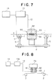
- FIG. 7 is a constitutional view of a hermetic coating electrical resistance measurement system as a further illustrative example of an electroconductive film inspection method and electroconductive film inspection system, which is not a subject-matter of the present invention but is described for better understanding the same.
- This system is one wherein the hermetically coated optical fiber 1 is made to pass through a hollow core type eddy current generation and inspection sensor 8A.
- the constituent elements of the hermetic coating electrical resistance measurement system of Fig. 7 corresponding to the constituent elements of the hermetic coating electrical resistance measurement system of Fig. 2 are given the same reference numerals.
- the hollow core type eddy current generation and inspection sensor 8A has the outer periphery of the coil 82 molded integrally with a plastic 83 and is provided with a through hole 84 inside.
- the hollow core type eddy current generation and inspection sensor 8A is arranged horizontally and has a hermetically coated optical fiber 1 passed through its through hole 84.
- Figure 8 is a constitutional view of a hermetic coating electrical resistance measurement system as a still further illustrative example of an electroconductive film inspection method and electroconductive film inspection system, which is not subject-matter of the present invention.
- This system is one in which the eddy current generation and inspection sensor 8 is made to vibrate with respect to the hermetically coated optical fiber 1.
- This eddy current generation and inspection sensor 8 is constituted in the same way as the eddy current generation and inspection sensor 8 shown in Fig. 3.
- the constituent elements of the hermetic coating electrical resistance measurement system of Fig. 8 corresponding to the constituent elements of the hermetic coating electrical resistance measurement system of Fig. 2 are given the same reference numerals.
- the eddy current generation and inspection sensor 8A1 is mounted to a vibrator 7A, which vibrator 7A is vibrated by the inspection apparatus 13A.
- the eddy current generation and inspection sensor 8A1 vibrates up and down with respect to the hermetically coated optical fiber 1.
- the relationship of approach and distancing of the hermetically coated optical fiber 1 and the eddy current generation and inspection sensor 8A1 is the same as the case in the hermetic coating electrical resistance measurement system of Fig. 2. Therefore, even in this system of Fig. 8, it is possible to calculate the electrical resistance of the hermetic coating 1c from the phase angle ⁇ of the complex impedance in the same way as above in the inspection apparatus 13A.
- the constituent conditions for the coil 82 in the eddy current generation and inspection sensor 8A1 in the system of Fig. 8 are shown in Table 3. Inside diameter of coil 82 1.6 mm Linear diameter of coil 82 0.05 mm Number of turns of coil 82 180 Length of coil 82 10 mm
- the frequency f 1 of the high frequency current for the generation of the eddy current applied to the coil 82 and the vibration frequency of the vibrator 7A are shown in Table 4.
- Vibration frequency of vibrator 7A 60 to 100 Hz
- the inspection apparatus 13A calculates the electrical resistance of the hermetic coating 1c from the above-mentioned measured phase angles ⁇ .
- the explanation was made of an example of measurement of the electrical resistance of the hermetic coating 1c in the state with the hermetically coated optical fiber 1 running with respect to the eddy current generation and inspection sensor 8, but the eddy current generation and inspection sensor 8 may also be moved with respect to the hermetically coated optical fiber 1. Further, the same measurement as above may be performed with the eddy current generation and inspection sensor 8 and the hermetically coated optical fiber 1 in the stationary state.
- Figure 10 is a constituent view of a hermetic coating electrical resistance measurement system as an embodiment of the electroconductive film inspection system using the electroconductive film inspection method of the present invention. Constituent elements in Fig. 10 the same as the constituent elements in Fig. 2 are given the same reference numerals.
- the hermetic coating electrical resistance measurement system of Fig. 10 is not provided with the vibrator 7 shown in Fig. 2.
- the constitution and the functions of the inspection apparatus 13B differ from those of the inspection apparatus 13 of Fig. 2.
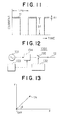
- the hermetic coating electrical resistance measurement system does not change the distance between the above-mentioned hermetically coated optical fiber 1 and the eddy current generation and inspection sensor 8 by physical vibration, but changes the eddy current generated at the hermetic coating electrically by applying the high frequency current turning on and off as shown in Fig. 11 to the eddy current generation and inspection coil 8.
- the inspection apparatus 13B has a power source which supplies to the inspection coil 82 of the eddy current generation and inspection sensor 8 an AC current of a high frequency f 1 sufficient for generating an eddy current in the hermetic coating 1c in the optical fiber 1.
- the inspection apparatus 13B has an addition circuit which is connected to a high frequency current generating power source and further adds to (superposes on) the high frequency current from the high frequency current generating power source an AC current having a low frequency, preferably as mentioned later a low frequency f 2 of less than 1/100th of the high frequency f 1 and of an amplitude larger than the amplitude of the high frequency AC current.
- the explanation will be made of the case of using the eddy current generation and inspection sensor 8 shown in Fig. 3 for measurement of the electrical resistance of the hermetic coating 1c of the hermetically coated optical fiber 1 shown in Fig. 4.
- the conditions of the coil 82 of the eddy current generation and inspection sensor 8 are shown in Table 6 and the current conditions applied to the coil 82 and running speed of the hermetically coated optical fiber 1 are shown in Table 7.
- the frequency of the current of the on timing is a high frequency f 1 , but the amplitude A1 is sufficiently smaller than the amplitude D1 when turned on and off.
- This turning on and off is for detecting the eddy current at the on time and the eddy current at the off time and enabling accurate measurement of the phase angle of the complex impedance vector defined by these two points.
- the inspection apparatus 13B has the power source circuit 13B1 shown in Fig. 12.
- a high frequency current is applied to the coil 82 of the eddy current generation and inspection sensor 8, an eddy current is generated at the hermetic coating 1c and the coil 82 detects this.
- the measurement values detected by the coil 2 are plotted by a recorder 14, as shown in Fig. 13, they are output as the complex impedance vector between two points ON and OFF with the phase angle ⁇ including information of the electrical resistance of the hermetic coating 1c.
- the output point ON at the on timing when the high frequency current is applied to the detection coil 82 of the eddy current generation and inspection sensor 8 is not a single exact point but extends in the direction of the phase angle ⁇ due to the vibration accompanying the movement of the running hermetically coated optical fiber 1.
- the zero point of the output can be freed of the effects caused by temperature drifting.
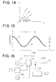
- Figure 14 is a graph of the results of actual measurement of the phase angles ⁇ a to ⁇ d with respect to the samples a, b, and c for three types of hermetic coatings 1c with different resistances under the above inspection conditions. These phase angles ⁇ a to ⁇ d are the same as those shown in Table 5. The hermetic coatings of the samples a, b, and c were subjected to destructive tests after on-line measurement, whereupon they were found to have the same resistances as shown in Table 5.
- the high frequency current is turned on and off, but in this embodiment the amplitude is changed sinusoidally.
- the amplitude A2 of the high frequency current is an effective value of 3 mA
- the amplitude A3 of the low frequency current is an effective value of 10 mA
- the DC bias current D2 is 20 mA.
- the inspection apparatus 13B has the power source 13B2 shown in Fig. 16.
- the added AC current is applied to the detection coil 82 of the eddy current generation and inspection sensor 8.
- the above-mentioned microcomputer-based computing means is built in or such a computing means is provided outside.
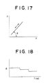
- Figure 18 shows the results of continuous measurement of the electrical resistance of the hermetic coating 1c in the process for forming the hermetic coating 1c of the hermetically coated optical fiber 1 having the sectional structure shown in Fig. 3.
- the horizontal axis of Fig. 18 shows the elapse of time, while the vertical axis shows the magnitude of the phase angle ⁇ .
- the concentration of the material gas is successively lowered, so the thickness of the hermetic coating 1c becomes smaller and the electrical resistance of the hermetic coating 1c becomes higher and as a result the phase angle ⁇ becomes successively smaller.
- the average intensity of the high frequency current flowing to the coil 82 be changed by a low frequency of no more than 1/100th of the high frequency f 1 .
- the changes in the average intensity include the intermittent turning on and off as shown in Fig. 11.
- electroconductive film inspection method of the present invention and electroconductive film inspection system using the same are not limited to inspected objects which are linear bodies like optical fibers, but can also be used for the case of on-line, continuous inspection of the state of formation of magnetic films.
- the present invention is suitable for measurement of the electrical resistance of a thin film conductor, but is not limited to a thin film and can be widely used for electroconductive films using eddy currents.
- the electroconductive film inspection method and apparatus of the present invention it is possible to measure the electrical resistance of an inspected object, that is, an electroconductive film, without regard to whether it is stationary or moving, in a nondestructive state, without contact, continuously, automatically, and stably at a high precision.
- the electrical resistance shows the state of formation of the electroconductive film. It is possible to evaluate on-line automatically the state of formation from the electrical resistance.
- the electroconductive film inspection method of the present invention it is possible to not only inspect the hermetically coated optical fiber cable after production but also to continuously test and evaluate, on-line, the state of formation of a hermetic coating 1c at the step of formation of the hermetic coating.
- Figure 19 is a constituent view of an optical fiber production system as a first electroconductive film production process and production system which is not a subject-matter of the present invention but is described for better understanding the present invention.
- the optical fiber production system is for forming an optical fiber line 1B comprised of a core la and a cladding 1b by drawing (spinning) an optical fiber preform 1A and has a drawing furnace 15 with a heater 15A disposed therein, a reaction tube (reaction furnace) 16, a laser fiber outer diameter measurement apparatus 19, a plastic coating die, a capstan roller 31, a dancer roller 32, and a takeup drum 33.
- the optical fiber production system further has a gas tank 34 filled with an inert gas used as a sealing gas or dilution gas, in this embodiment, nitrogen (N 2 ) gas, a gas tank 35 filled with a hermetic coating forming material gas, in this embodiment, acetylene (C 2 H 2 ) gas, and mass flow controllers (MFC) 23 to 26 for controlling the flow of the same.
- the optical fiber production system further has an eddy current generation and inspection sensor 8, an electrical resistance measurement apparatus 21 for supplying high frequency current to the coil 82 of the eddy current generation and inspection sensor 8 and measuring the electrical resistance of the hermetic coating 1c, and a process control apparatus 22.
- the electrical resistance measurement apparatus 21 corresponds to the above-mentioned inspection apparatuses 13, 13B, etc.
- the reaction tube 16 has an upper sealing gas inlet 16A for filling the sealing gas, i.e., N 2 gas, into the upper sealing zone from the nitrogen gas tank 34 and a lower sealing gas inlet 16C for filling N 2 gas into the lower sealing zone.
- the mass control of the sealing gas is performed by the MFC's 23 and 26.
- the material gas inlet 16B At the bottom of the upper sealing gas inlet 16A is provided the material gas inlet 16B.
- C 2 H 2 is introduced as the material gas and N 2 gas as the dilution gas by these MFC 24 and MFC 25 to the reaction tube 16E. Used gas is discharged by an exhaust pump 8 from the discharge port 16D.
- the inside space 16E between the upper sealing gas inlet 16A and the lower sealing gas inlet 16C is the reaction portion 16E for forming the hermetic coating 1c.
- a pressure sensor 17 is provided for measuring the pressure of the reaction portion 16E.
- the preform 1A is drawn into a line by the drawing furnace 15 to form an optical fiber line 1B having a cross-section as shown in Fig. 3 and, for example, a core 1a of a diameter of 10 microns and a cladding 1b of an outer diameter of 125 microns formed at the outside of the core 1a.
- the optical fiber line 1B is introduced into the reaction tube 16 and the heat of the optical fiber line 1B itself just after being led out of the drawing furnace 15 or that heat and the heat from a heater (not shown) disposed outside of the reaction tube 16 are used for a heating reaction of the acetylene gas (C 2 H 2 ) gas introduced into the reaction tube 16B so that carbon is precipitated on the surface of the cladding 1b and an amorphous carbon hermetic coating 1c of a thickness of 500 to 1000 ⁇ is formed.
- the result is drawn out of the reaction tube 16 as the naked optical fiber line 1C.
- the MFC's 24 and 25 perform suitable mass (flow rate) control of the C 2 H 2 gas and N 2 gas so that the hermetic coating 1c is formed.
- the naked optical fiber line 1C is measured as to its outer diameter when passing through the laser outer diameter measurement apparatus 19.
- the optical fiber 1c passing through the laser outer diameter measurement apparatus 19 has deposited on it at the plastic coating die 20 a plastic coating as a protective coating 1d to form the hermetically coated optical fiber 1.
- the hermetically coated optical fiber 1 is conveyed via the capstan roller 31 and dancer roller 32 and taken up on a takeup drum 33.
- the capstan roller 31 and dancer roller 32 have arranged between them close to the moving hermetically coated optical fiber 1 the eddy current generation and inspection sensor 8 which measures on-line the electrical resistance of the hermetic coating 1c in a noncontact state from the outside of the plastic coating 1d.
- the sectional structure of the eddy current generation and inspection sensor 8 is the same as the structure shown in Fig. 3.
- the electrical resistance measurement apparatus 21 has the same type of power source as the power source 13B shown in Fig. 12.
- the current of the waveform shown in Fig. 11 from the power source is applied to the coil 82 of the eddy current generation and inspection sensor 8.
- the turning on and off is for detecting the eddy current at the on time and the eddy current at the off time and enabling accurate measurement of the phase angle of the complex impedance vector defined by these two points.
- Figure 20 shows the changes in the electrical resistance of the hermetic coating 1.
- the curve CV1 shows the changes when the MFC 24 introduces C 2 H 2 gas into the material gas feed inlet 16B under the same set conditions.
- the electrical resistance of the hermetic coating 1c is around 10 kilohms/cm, but the curve CV1 shows that even when the MFC 24 is at the same setting, the electrical resistance of the hermetic coating 1c increases along with the passage of time, in other words, the thickness becomes smaller.
- the reason for this it is believed that along with the elapse of time, carbon adheres to the inside walls of the reaction tube 16E making the tube diameter smaller and increasing the flow rate of the gas, so the amount of carbon adhering to the outer surface of the cladding 1b becomes smaller.
- the electrical resistance of the hermetic coating 1c calculated at the electrical resistance measurement apparatus 21 is output to the process control apparatus 22.
- the process control apparatus 22 outputs control commands to the MFC 24 so that the electrical resistance becomes in a predetermined range, for example, 10 kilohms/cm.
- the MFC 24 reduces the flow rate of the C 2 H 2 introduced from the acetylene gas tank 35 to the reaction portion 16E based on the control commands from the process control apparatus 22 so that an amorphous carbon coating 1c with a predetermined thickness is formed on the outer surface of the cladding 1b.
- the flow rate of the C 2 H 2 gas is controlled to maintain the electrical resistance of the hermetic coating 1c to about 10 kilohms/cm as shown by the curve CV2 of Fig. 20 and to make the thickness of the hermetic coating 1c, for example, 1000 ⁇ .
- Figure 21 shows an optical fiber production system as a second electroconductive film production system for working an electroconductive film production process, which is not a subject-matter of the present invention but is described for better understanding the present invention.
- This system is comprised so that the settings of the thermostat 27 controlling the heater 15A are changed based on the feedback signals S22 from the process control apparatus 22. That is, this system does not control the carbon flow rate directly as in the first embodiment, but controls the drawing temperature at the drawing furnace 15.
- Figures 22(A) to (C) show the relationship between the electrical resistance and the drawing temperature. These figures show the drawing temperature and line speed at electrical resistances of 10, 15, and 20 kilohms. If the drawing temperature is reduced, the diameter of the optical fiber line 1B becomes smaller and the line speed becomes slower. By this, it is possible to effectively reduce the decomposition temperature of the material gas. Further, as mentioned with reference to the first embodiment, the electrical resistance rises due to the changes in the reaction tube 16E, so in the individual set conditions, the drawing temperature is gradually raised so that the electrical resistance of the hermetic coating 1c is constant.
- the eddy current generation and inspection sensor 8 may be placed between the plastic coating die 20 and capstan roller 31. Further, in the present invention, the eddy current generation and inspection sensor 8 and the hermetic coating 1c do not contact each other, so may be placed between a laser outer diameter measurement apparatus 19 and plastic coating die 20 making it possible to measure the electrical resistance of the hermetic coating 1c as well.
- the high frequency current applied to the eddy current generation and inspection sensor 8 may be that shown in the above-mentioned Fig. 11 and in addition the current shown in Fig. 15 may be applied.
- the amplitude A2 of the high frequency current is an effective value of 3 mA
- the amplitude A3 of the low frequency current is an effective value of 10 mA
- the DC bias current D2 is 20 mA.
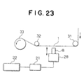
- Figure 23 shows the partial constitution of the optical fiber production system shown in Fig. 19 and Fig. 21.
- This vibration substantially equivalently changes the average power by adding the above-mentioned high frequency current to the low frequency current. Therefore, it is possible by this method too to accurately measure without contact and on-line the electrical resistance of the hermetic coating 1c in the moving hermetically coated optical fiber 1.
- the eddy current generation and inspection sensor 8 may also be fixed in place and a moving hermetically coated optical fiber 1 made to vibrate with respect to the eddy current generation and inspection sensor 8.
- an electroconductive film such as the electroconductive hermetic coating in a moving hermetically coated optical fiber
- an eddy current is generated in the above-mentioned semiconductor substrate film or magnetic film in a noncontact state and the eddy current is measured to measure the electrical resistance of the film.
- the eddy current generation and inspection sensor is run in a noncontact state in two-dimensions or the film being inspected is run in a noncontact state in two-dimensions with respect to a fixed eddy current generation and inspection sensor for measurement over the entire film.
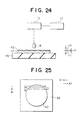
- Figure 24 shows a constitutional view of a system for inspection of the state of formation of an electroconductive film.
- the formation state inspection system of an electroconductive film use is made of the above-mentioned inspection apparatus 13, recorder 14, and eddy current generation and inspection sensor 8 so as to measure the electrical resistance of the active layer 42 formed on the surface of a wafer 42 placed on a moving stage 45.
- the moving stage 45 as shown in Fig. 25, is moved in the direction A1, is moved in the direction B a predetermined distance, and is moved in the direction A2 reverse to the direction A1. This movement operation is repeated so that the entire surface of the active layer 42 is swept.
- the movement distance in the direction B is made a distance sufficient for generation and detection of the eddy current.
- the movement of the moving stage 45 is controlled using a microcomputer in the inspection apparatus 13.
- phase angle ⁇ of the complex impedance vector showing the thickness and electrical resistance at a position of the active layer 42 detected by the eddy current generation and inspection sensor 8 in the process of movement of the moving stage 45 becomes as shown in Fig. 13 and is recorded in the recorder 14.
- the distance t3 between the eddy current generation and inspection sensor 8 and active layer 42 is 500 microns
- the thickness t2 of the active layer 42 is 0.5 micron
- the thickness tl of the wafer 41 is 0.4 mm. Note that the amplitude between the two points changes depending on the distance t3 between the eddy current generation and inspection sensor 8 and the active layer 42.
- Figure 26 and Fig. 27 show graphs based on the present system.
- Figure 26 shows the changes (vertical axis) in the phase angle ⁇ when growing on a GaAs substrate used as the wafer 41 a nondoped GaAs, AlGaAs film as an active layer 42, then growing sulfur S-doped gaAs to 0.5 micron and changing the concentration of impurities (horizontal axis) to 1 x 10 17 cm -3 , 2 x 10 17 cm -3 , and 3 x 10 17 cm -3 .
- the higher the concentration of impurities the smaller the relative resistance of the semiconductor and as a result the smaller the resistance and the larger the phase angle 10 ⁇ .
- Figure 27 shows the changes (vertical axis) of the phase angle ⁇ when fixing the concentration of impurities to 2 x 10 17 cm -3 and changing the thickness t2 (horizontal axis) to 0.4 micron, 0.5 micron, and 0.6 micron.
- the above results are calculated by the inspection apparatus 13. Therefore, in the inspection apparatus 13, it is possible to determine the thickness of the active layer 42 and the concentration of inpurities.
- the wafer temperature has an effect on the concentration of the dopant and the distribution of thickness and in particular has a large effect on the concentration of the dopant. Therefore, even if the thickness distribution is constant, a spread appears in the concentration of the dopant.
- the graph of Fig. 28 shows this feature.
- the horizontal axis shows the wafer position and the vertical axis the phase angle ⁇ .
- the thickness t2 of the wafer is fixed at 0.5 micron.
- the curves CV11 and CV12 show the changes in the phase angle ⁇ due to the change of the concentration of impurities n1 and n2. Further, the phase angle ⁇ changes depending on the wafer position. By scanning the wafer as a whole by the sensor 8, it is possible to evaluate overall that wafer.
- the inspection apparatus 13 When measuring at a high density with the distance of measurement on the plane of the active 42 being made smaller, the measurement time sometimes is a long time of from several minutes to several tens of minutes. In such long time measurement, the problem sometimes occurs in the high frequency electrical system of the inspection apparatus 13 of zero drift due to temperature changes etc. If the measurement values in this case are plotted, the result becomes as shown in Fig. 1. To eliminate the problem of drift, as mentioned above, the distance between the eddy current generation and inspection sensor 8 and the active layer 42 is changed at a period sufficiently lower than the high frequency of the high frequency current applied to the eddy current generation and or the average intensity of the high frequency current applied to the eddy current generation and inspection sensor 8 is changed at a low frequency. Therefore, the inspection apparatus 13 is constructed as explained above.
Landscapes
- Chemical & Material Sciences (AREA)
- Physics & Mathematics (AREA)
- General Physics & Mathematics (AREA)
- General Health & Medical Sciences (AREA)
- Health & Medical Sciences (AREA)
- Life Sciences & Earth Sciences (AREA)
- Analytical Chemistry (AREA)
- Biochemistry (AREA)
- Electrochemistry (AREA)
- Chemical Kinetics & Catalysis (AREA)
- Immunology (AREA)
- Pathology (AREA)
- Investigating Or Analyzing Materials By The Use Of Magnetic Means (AREA)
- Surface Treatment Of Glass Fibres Or Filaments (AREA)
- Testing Of Optical Devices Or Fibers (AREA)
- Investigating Or Analysing Materials By Optical Means (AREA)
Claims (38)
- Verfahren zum Untersuchen eines elektrisch leitfähigen Filmes, mitdadurch gekennzeichnet,einem Verfahrensschritt des Veränderns einer durchschnittlichen Feldstärke eines Magnetfeldes einer Frequenz, die zur Erzeugung eines Wirbelstromes in einem untersuchten elektrisch leitfähigen Film (1c, 42) ausreicht, mittels einer Frequenz, die ausreichend niedriger ist als die Hochfrequenz des hochfrequenten Magnetfeldes, und des Anlegens des hochfrequenten Magnetfeldes aus der Nähe des elektrisch leitfähigen Filmes (1c, 42) an den elektrisch leitfähigen Film (1c, 42), um einen Wirbelstrom in dem elektrisch leitfähigen Film (1c, 42) zu erzeugen;einem Verfahrensschritt des Erfassens des in dem elektrisch leitfähigen Film (1c, 42) erzeugten Wirbelstromes; undeinem Verfahrensschritt des Berechnens eines elektrischen Widerstandes des elektrisch leitfähigen Filmes (1c, 42), der einem Phasenwinkel eines komplexen Impedanzvektors entspricht, basierend auf dem erfaßten Wirbelstrom,daß ein Gleich-Vormagnetisierungsstrom zu dem hochfrequenten Strom zur Erzeugung des hochfrequenten Magnetfeldes hinzuaddiert wird, und daß der mit dem Vormagnetisierungsstrom addierte hochfrequente Strom mit der niedrigen Frequenz ein- und ausgeschaltet wird, um die durchschnittliche Feldstärke zu verändern.
- Verfahren zum Untersuchen eines elektrisch leitfähigen Filmes, mitdadurch gekennzeichnet,einem Verfahrensschritt des Veränderns einer durchschnittlichen Feldstärke eines Magnetfeldes einer Frequenz, die zur Erzeugung eines Wirbelstromes in einem untersuchten elektrisch leitfähigen Film (1c, 42) ausreicht, mittels einer Frequenz, die ausreichend niedriger ist als die Hochfrequenz des hochfrequenten Magnetfeldes, und des Anlegens des hochfrequenten Magnetfeldes aus der Nähe des elektrisch leitfähigen Filmes (1c, 42) an den elektrisch leitfähigen Film (1c, 42), um einen Wirbelstrom in dem elektrisch leitfähigen Film (1c, 42) zu erzeugen;einem Verfahrensschritt des Erfassens des in dem elektrisch leitfähigen Film (1c, 42) erzeugten Wirbelstromes; undeinem Verfahrensschritt des Berechnens eines elektrischen Widerstandes des elektrisch leitfähigen Filmes (1c, 42), der einem Phasenwinkel eines komplexen Impedanzvektors entspricht, basierend auf denn erfaßten Wirbelstrom,daß ein Gleich-Vormagnetisierungsstrom zu dem hochfrequenten Strom zur Erzeugung des hochfrequenten Magnetfeldes hinzuaddiert wird, und daß weiter ein Wechselstrom der niedrigen Frequenz mit einer vorbestimmten Amplitude hinzuaddiert wird, um die durchschnittliche Feldstärke zu verändern.
- Verfahren zum Untersuchen eines elektrisch leitfähigen Filmes nach Anspruch 1 oder 2,
dadurch gekennzeichnet,daß ein Element (1a, 1b, 41), das den elektrisch leitfähigen Film (1c, 42) trägt, mit der niedrigen Frequenz zum Schwingen gebracht wird und daß ein Abstand zwischen einer Wirbelstrom-Erzeugungs- und -Prüf-Spule (82), die in der Nähe des elektrisch leitfähigen Filmes (1c, 42) angeordnet ist, und dem elektrisch leitfähigen Film (1c, 42) mit der niedrigen Frequenz verändert wird. - Verfahren zum Untersuchen eines elektrisch leitfähigen Filmes nach Anspruch 1 oder 2,
dadurch gekennzeichnet,daß der hochfrequente Strom zum Erzeugen des hochfrequenten Magnetfeldes einer Wirbelstrom-Erzeugungs- und -Prüf-Spule (82) zugeführt wird, die in der Nähe des elektrisch leitfähigen Filmes (1c, 42) angeordnet ist, und daß der Abstand zwischen der Spule (82) und dem elektrisch leitfähigen Film (1c, 42) mit einer Schwingungsfrequenz der niedrigen Frequenz verändert wird. - Verfahren zum Untersuchen eines elektrisch leitfähigen Filmes nach Anspruch 1 oder 2,
dadurch gekennzeichnet,daß der elektrisch leitfähige Film (1c) eine elektrisch leitfähige, hermetische Beschichtiing auf einer Oberfläche einer Hülle (1b) einer Lichtleiterfaser (1B) mit einem Kern (1a) und einer Hülle (1b) ist. - Verfahren zum Untersuchen eines elektrisch leitfähigen Filmes nach Anspruch 5,
dadurch gekennzeichnet,daß die hermetische Beschichtung (1c) eine Dicke von etwa 500 bis 1000 Å und einen elektrischen Widerstand von etwa mehreren bis mehreren Zehn kΩ/cm hat, und die Frequenz des hochfrequenten Stromes etwa 1 bis 5 MHz beträgt. - Verfahren zum Untersuchen eines elektrisch leitfähigen Filmes nach Anspruch 6,
dadurch gekennzeichnet,daß die ausreichend niedrige Frequenz nicht größer ist als etwa 1/100 der ausreichend hohen Frequenz zur Erzeugung eines Wirbelstromes. - Verfahren zum Untersuchen eines elektrisch leitfähigen Filmes nach Anspruch 7,
dadurch gekennzeichnet,daß die Messung des elektrischen Widerstandes der hermetischen Beschichtung (1c) von außerhalb eines Schutzüberzuges (1d), der auf der Außenseite der hermetischen Beschichtung (1c) gebildet ist, durchgeführt wird. - Verfahren zum Untersuchen eines elektrisch leitfähigen Filmes nach Anspruch 8,
dadurch gekennzeichnet,daß Messung des elektrischen Widerstandes der hermetischen Beschichtung (1c) kontinuierlich während der Bewegung eines Lichtleiters (1) mit der hermetischen Beschichtung (1c) durchgeführt wird. - Verfahren zum Untersuchen eines elektrisch leitfähigen Filmes nach Anspruch 8,
dadurch gekennzeichnet,daß Messung des elektrischen Widerstandes der hermetischen Beschichtung (1c) in einem stationären Zustand eines Lichtleiters (1) mit der hermetischen Beschichtung (1c) durchgeführt wird. - Verfahren zum Untersuchen eines elektrisch leitfähigen Filmes nach Anspruch 1 oder 2,
dadurch gekennzeichnet,daß der elektrisch leitfähige Film (42) ein magnetischer Film ist. - Verfahren zum Untersuchen eines elektrisch leitfähigen Filmes nach Anspruch 1 oder 2,
dadurch gekennzeichnet,daß das Verfahren weiter einen Verfahrensschritt des Auswertens eines Formierungszustandes des elektrisch leitfähigen Filmes (1c) aus dem berechneten elektrischen Widerstand aufweist. - System zum Untersuchen eines elektrisch leitfähigen Filmes, mitdadurch gekennzeichnet,einem Wirbelstrom-Erzeugungs- und -Erfassungs-Sensor (8, 8A, 8A1), der in der Nähe eines zu untersuchenden elektrisch leitfähigen Filmes (1c, 42) angeordnet ist;einer Hochfrequenz-Stromquelle (131), die einen hochfrequenten Strom erzeugt, der ausreichend hochfrequent ist, um in dem elektrisch leitfähigen Film (1c, 42) einen Wirbelstrom zu erzeugen, und die den hochfrequenten Strom dem Wirbelstrom-Erzeugungs- und -Erfassungs-Sensor (8, 8A, 8A1) zuführt;einer Einrichtung zum Verändern der durchschnittlichen Stromstärke, die den hochfrequenten Strom von der Hochfrequenz-Stromquelle (131) dem Wirbelstrom-Erzeugungs- und -Erfassungs-Sensor (8, 8A, 8A1) zuführt und dabei dessen durchschnittliche Stromstärke mit einer Frequenz verändert, die ausreichend niedriger als die Frequenz des hochfrequenten Stromes ist; undeiner Einrichtung zum Berechnen des elektrischen Widerstandes des elektrisch leitfähigen Filmes (1c, 42) aus dem von dem Wirbelstrom-Erzeugungs- und - Erfassungs-Sensor (8, 8A, 8A1) erfaßten Wirbelstrom.daß die Einrichtung zum Verändern der durchschnittlichen Stromstärke eine Gleich-Vormagnetisierungs-Stromquelle zum Erzeugen eines Gleich-Vormagnetisierungsstromes zum Vormagnetisieren des hochfrequenten Stromes, eine Schaltung (134) zum Hinzuaddieren des Gleich-Vormagnetisierungsstromes zu dem hochfrequenten Strom, und eine Schalteinrichtung (135) zum Ein- und Ausschalten des vormagnetisierten, hochfrequenten Stromes aus der Additionsschaltung (134) mit einer ausreichend niedrigen Frequenz aufweist.
- System zum Untersuchen eines elektrisch leitfähigen Filmes, mitdadurch gekennzeichnet,einem Wirbelstrom-Erzeugungs- und -Erfassungs-Sensor (8, 8A, 8A1), der in der Nähe eines zu untersuchenden elektrisch leitfähigen Filmes (1c, 42) angeordnet ist;einer Hochfrequenz-Stromquelle (131), die einen hochfrequenten Strom erzeugt, der ausreichend hochfrequent ist, um in dem elektrisch leitfähigen Film (1c, 42) einen Wirbelstrom zu erzeugen, und die den hochfrequenten Strom dem Wirbelstrom-Erzeugungs- und -Erfassungs-Sensor (8, 8A, 8A1) zuführt;einer Einrichtung zum Verändern der durchschnittlichen Stromstärke, die den hochfrequenten Strom von der Hochfrequenz-Stromquelle (131) dem Wirbelstrom-Erzeugungs- und -Erfassungs-Sensor (8, 8A, 8A1) zuführt und dabei dessen durchschnittliche Stromstärke mit einer Frequenz verändert, die ausreichend niedriger als die Frequenz des hochfrequenten Stromes ist; undeiner Einrichtung zum Berechnen des elektrischen Widerstandes des elektrisch leitfähigen Filmes (1c, 42) aus dem von dem Wirbelstrom-Erzeugungs- und-Erfassungs-Sensor (8, 8A, 8A1) erfaßten Wirbelstrom,daß die Einrichtung zum Verändern der durchschnittlichen Stromstärke eine Gleich-Vormagnetisierungs-Stromquelle zum Erzeugen eines Gleich-Vormagnetisierungsstromes zum Vormagnetisieren des hochfrequenten Stromes, eine Niederfrequenz-Stromquelle (136) zum Erzeugen eines Wechsel stromes von ausreichend niedriger Frequenz und mit einer vorbestimmten Amplitude, und eine Schaltung (134) zum Addieren des hochfrequenten Stromes aus der Hochfrequenz-Stromquelle (131), des Gleich-Vormagnetisierungsstromes aus der Gleich-Vormagnetisierungs-Stromquelle und eines niederfrequenten Stromes aus der Niederfrequenz-Stromquelle (136) aufweist.
- System zum Untersuchen eines elektrisch leitfähigen Filmes nach Anspruch 13 oder 14,
dadurch gekennzeichnet,daß die Einrichtung zum Verändern der durchschnittlichen Stromstärke eine Schwingungseinrichtung (7, 7A) zum Verändern eines Abstandes zwischen dem Wirbelstrom-Erzeugungs- und -Erfassungs-Sensor (8, 8A, 8A1) und dem elektrisch leitfähigen Film (1c, 42) mit der ausreichend niedrigen Frequenz aufweist. - System zum Untersuchen eines elektrisch leitfähigen Filmes nach Anspruch 14,
dadurch gekennzeichnet,daß die Schwingungseinrichtung (7, 7A) eine Einrichtung zum Schwingen des Wirbelstrom-Erzeugungs- und -Erfassungs-Sensors (8, 8A, 8A1) aufweist, um einen Abstand zu dem elektrisch leitfähigen Film (1c, 42) zu verändern. - System zum Untersuchen eines elektrisch leitfähigen Filmes nach Anspruch 14,
dadurch gekennzeichnet,daß die Schwingungseinrichtung (7, 7A) eine Einrichtung zum Schwingen des elektrisch leitfähigen Filmes (1c, 42) aufweist, um einen Abstand zu dem Wirbelstrom-Erzeugungs- und -Erfassungs-Sensor (8, 8A, 8A1) zu verändern. - System zum Untersuchen eines elektrisch leitfähigen Filmes nach Anspruch 13 oder 14,
dadurch gekennzeichnet,daß die Einrichtung zum Berechnen des elektrischen Widerstandes einen Rechner aufweist. - System zum Untersuchen eines elektrisch leitfähigen Filmes nach Anspruch 13 oder 14,
dadurch gekennzeichnet,daß der elektrisch leitfähige Film eine elektrisch leitfähige, hermetische Beschichtung (1c) auf einer Oberfläche der Hülle (1b) einer Lichtleiterfaser (1B) mit einem Kern (1a) und einer Hülle (1b) ist. - System zum Untersuchen eines elektrisch leitfähigen Filmes nach Anspruch 19,
dadurch gekennzeichnet,daß die hermetische Beschichtung (1c) eine Dicke von etwa 500 bis 1000 Å und einen elektrischen Widerstand von etwa mehreren bis mehreren Zehn kΩ/cm hat, und die Frequenz des hochfrequenten Stromes etwa 1 bis 5 MHz beträgt. - System zum Untersuchen eines elektrisch leitfähigen Filmes nach Anspruch 20,
dadurch gekennzeichnet,daß die ausreichend niedrige Frequenz nicht größer ist als etwa 1/100 der ausreichend hohen Frequenz zur Erzeugung eines Wirbel stromes. - System zum Untersuchen eines elektrisch leitfähigen Filmes nach Anspruch 13 oder 14,
dadurch gekennzeichnet,daß der elektrisch leitfähige Film (42) ein magnetischer Film ist. - Verfahren zum Untersuchen eines elektrisch leitfähigen Filmes nach den Ansprüchen 1 bis 12,
dadurch gekennzeichnet,daß das Verfahren bewirkt, daß ein Wirbelstrom in einem nicht-kontaktierenden Zustand in einem elektrisch leitfähigen Film (1c, 42) erzeugt wird, der auf einem Substrat (1a, 1b, 41) ausgebildet ist, das Verfahren den erzeugten Wirbelstrom erfaßt, und den Formierungszustand des elektrisch leitfähigen Filmes (1c, 42) aus dem Phasenwinkel des aus den erfaßten Werten berechneten komplexen Impedanzvektors untersucht. - Verfahren zum Untersuchen eines elektrisch leitfähigen Filmes nach Anspruch 23,
dadurch gekennzeichnet,daß der elektrisch leitfähige Film (42) ein sich auf einer Ebene ausbreitender Film ist, und der Wirbelstrom-Erzeugungs- und -Prüf-Sensor (8) zum zweidimensionalen Scannen der Oberfläche des elektrisch leitfähigen Filmes (42) ausgebildet ist, um die Untersuchung des Formierungszustandes über den gesamten elektrisch leitfähigen Film (42) zu ermöglichen. - Verfahren zum Untersuchen eines elektrisch leitfähigen Filmes nach Anspruch 23,
dadurch gekennzeichnet,daß die Wirbelstrom-Erzeugungs- und -Prüf-Einrichtung (8, 8A, 8A1) eine Veränderung einer durchschnittlichen Feldstärke eines Magnetfeldes einer zur Erzeugung eines Wirbelstromes in dem elektrisch leitfähigen Film (1c, 42) ausreichend hohen Frequenz mit einer Frequenz bewirkt, die ausreichend niedriger ist als die Hochfrequenz des hochfrequenten Magnetfeldes, und daß das hochfrequente Magnetfeld dem elektrisch leitfähigen Film (1c, 42) aus der Nähe des elektrisch leitfähigen Filmes (1c, 42) angelegt wird. - Verfahren zum Untersuchen eines elektrisch leitfähigen Filmes nach Anspruch 25,
dadurch gekennzeichnet,daß ein Gleich-Vormagnetisierungsstrom zu dem das hochfrequente Magnetfeld erzeugenden hochfrequenten Strom hinzuaddiert wird, und daß der hochfrequente Strom mit dem hinzuaddierten Vormagnetisierungsstrom mit einer niedrigen Frequenz ein- und ausgeschaltet wird, um die durchschnittliche Feldstärke zu verändern. - Verfahren zum Untersuchen eines elektrisch leitfähigen Filmes nach Anspruch 25,
dadurch gekennzeichnet,daß ein Gleich-Vormagnetisierungsstrom zu dem das hochfrequente Magnetfeld erzeugenden hochfrequenten Strom hinzuaddiert wird, ein Wechselstrom mit einer vorbestimmten Amplitude und niedriger Frequenz hinzuaddiert wird, und daß die durchschnittliche Feldstärke verändert wird. - Verfahren zum Untersuchen eines elektrisch leitfähigen Filmes nach Anspruch 23,
dadurch gekennzeichnet,daß ein Abstand zwischen dem elektrisch leitfähigen Film (1c, 42) und dem Wirbelstrom-Erzeugungs- und -Prüf-Sensor (8, 8A, 8A1) mit einer Frequenz verändert wird, die ausreichend niedriger ist als die Frequenz des den Wirbelstrom erzeugenden hochfrequenten Stromes. - Verfahren zum Untersuchen eines elektrisch leitfähigen Filmes nach Anspruch 23,
dadurch gekennzeichnet,daß der elektrisch leitfähige Film (42) eine elektrisch leitfähige Wirkschicht auf einem Halbleiter-Wafer (41) ist. - Verfahren zum Untersuchen eines elektrisch leitfähigen Filmes nach Anspruch 23,
dadurch gekennzeichnet,daß der elektrisch leitfähige Film ein elektrisch leitfähiger Film auf einem Glas-Substrat ist. - System zum Untersuchen eines Formierungszustandes miteinem System zum Untersuchen eines elektrisch leitfähigen Filmes nach den Ansprüchen 13 bis 22, undeiner Einrichtung zum Berechnen eines Phasenwinkels eines aus den Erfassungswerten berechneten komplexen Impedanzvektors, um so den Formierungszustand des elektrisch leitfähigen Filmes zu untersuchen.
- System zum Untersuchen eines Formierungszustandes nach Anspruch 31,
dadurch gekennzeichnet,daß die Wirbelstrom-Erzeugungs- und -Erfassungs-Einrichtung einen Wirbelstrom-Erzeugungs- und -Prüf-Sensor (8, 8A, 8A1) und eine Einrichtung aufweist, die bewirkt, daß der Wirbelstrom-Erzeugungs- und -Prüf-Sensor die Oberfläche des elektrisch leitfähigen Filmes (1c, 42) zweidimensional scannt und die Untersuchung des Formierungszustandes über den gesamten elektrisch leitfähigen Film (1c, 42) möglich ist. - System zum Untersuchen eines Formierungszustandes nach Anspruch 32,
dadurch gekennzeichnet,daß die Einrichtung zum Untersuchen des Formierungszustandes bewirkt, daß der Wirbelstrom-Erzeugungs- und -Prüf-Sensor (8, 8A, 8A1) eine durchschnittliche Feldstärke eines Magnetfeldes von zur Erzeugung eines Wirbelstromes in dem elektrisch leitfähigen Film (1c, 42) ausreichend hohen Frequenz mit einer Frequenz verändert, die ausreichend niedriger ist als die Hochfrequenz des hochfrequenten Magnetfeldes, und daß das hochfrequente Magnetfeld dem elektrisch leitfähigen Film (1c, 42) aus der Nähe des elektrisch leitfähigen Filmes (1c, 42) angelegt wird, um die Erzeugung eines Wirbelstromes in dem elektrisch leitfähigen Film zu bewirken. - System zum Untersuchen eines Formierungszustandes nach Anspruch 33,
dadurch gekennzeichnet,daß die Einrichtung zum Verändern der durchschnittlichen Stromstärke des hochfrequenten Stromes den Gleichstrom-Vormagnetisierungsstrom dem hochfrequenten Strom, der der Erzeugung des hochfrequenten Magnetfeldes dient, hinzuaddiert und die durchschnittliche Stromstärke durch Ein- und Ausschalten des hochfrequenten Stromes, dem der Vormagnetisierungsstrom hinzuaddiert wurde, mit der obigen Niederfrequenz verändert. - System zum Untersuchen eines Formierungszustandes nach Anspruch 33,
dadurch gekennzeichnet,daß die Einrichtung zum Verändern der durchschnittlichen Stromstärke des hochfrequenten Stromes den Gleich-Vormagnetisierungsstrom dem hochfrequenten Strom, der der Erzeugung des hochfrequenten Magnetfeldes dient, hinzuaddiert und weiter einen Wechselstrom mit einer vorbestimmten Amplitude und einer niedrigen Frequenz hinzuaddiert, um die durchschnittliche Stromstärke zu verändern. - System zum Untersuchen eines Formierungszustandes nach Anspruch 31,
dadurch gekennzeichnet,daß die Wirbelstrom-Erzeugungs- und -Prüf-Einrichtung bewirkt, daß der Abstand zwischen dem elektrisch leitfähigen Film (1c, 42) und dem Wirbelstrom-Erzeugungs- und -Prüf-Sensor (8, 8A, 8A1) mit einer Frequenz verändert wird, die ausreichend niedriger ist als die Frequenz des hochfrequenten Stromes zur Erzeugung des Wirbel stromes. - System zum Untersuchen eines Formierungszustandes nach Anspruch 32,
dadurch gekennzeichnet,daß der elektrisch leitfähige Film eine elektrisch leitfähige Wirkschicht (42) auf einem Halbleiter-Wafer (41) ist. - System zum Untersuchen eines Formierungszustandes nach Anspruch 32,
dadurch gekennzeichnet,daß der elektrisch leitfahige Film ein elektrisch leitfähiger Film auf einem Glas-Substrat ist.
Applications Claiming Priority (6)
| Application Number | Priority Date | Filing Date | Title |
|---|---|---|---|
| JP2140332A JP2733544B2 (ja) | 1990-05-30 | 1990-05-30 | 導電性薄膜検査方法 |
| JP140332/90 | 1990-05-30 | ||
| JP10873391A JP2635844B2 (ja) | 1991-04-12 | 1991-04-12 | 導電膜検査方法およびその装置 |
| JP108733/91 | 1991-04-12 | ||
| JP3108734A JP2566069B2 (ja) | 1991-04-12 | 1991-04-12 | ハーメチック被覆光ファイバの製造方法とその装置 |
| JP108734/91 | 1991-04-12 |
Publications (3)
| Publication Number | Publication Date |
|---|---|
| EP0459441A2 EP0459441A2 (de) | 1991-12-04 |
| EP0459441A3 EP0459441A3 (en) | 1993-02-10 |
| EP0459441B1 true EP0459441B1 (de) | 1999-03-31 |
Family
ID=27311304
Family Applications (1)
| Application Number | Title | Priority Date | Filing Date |
|---|---|---|---|
| EP91108787A Expired - Lifetime EP0459441B1 (de) | 1990-05-30 | 1991-05-29 | Verfahren und Vorrichtung zur Untersuchung von einem elektrisch leitfähigen Film mit Wirbelströmen sowie deren Anwendung zur Produktion von optischen Glasfasern |
Country Status (6)
| Country | Link |
|---|---|
| US (3) | US5262726A (de) |
| EP (1) | EP0459441B1 (de) |
| KR (1) | KR910020449A (de) |
| AT (1) | ATE178406T1 (de) |
| CA (1) | CA2043347A1 (de) |
| DE (1) | DE69131059T2 (de) |
Families Citing this family (22)
| Publication number | Priority date | Publication date | Assignee | Title |
|---|---|---|---|---|
| CA2043347A1 (en) * | 1990-05-30 | 1991-12-01 | Yukio Kohmura | Method and system for inspection of electroconductive film using eddy current and process and system for production of optical fibres using method and system |
| DE9206076U1 (de) * | 1992-05-07 | 1993-09-09 | Heinrich Hermann GmbH + Co, 70327 Stuttgart | Etikettiermaschine |
| FR2692978A1 (fr) * | 1992-06-30 | 1993-12-31 | Alcatel Fibres Optiques | Dispositif et procédé de contrôle de l'épaisseur et de la régularité d'un revêtement déposé sur un corps isolant allongé. |
| US6165542A (en) * | 1998-12-23 | 2000-12-26 | United Technologies Corporation | Method for fabricating and inspecting coatings |
| DE10032143C2 (de) * | 1999-09-30 | 2002-07-18 | Heidenhain Gmbh Dr Johannes | Ferraris-Sensor und Verfahren zum Betrieb eines Ferraris-Sensors |
| US6433541B1 (en) | 1999-12-23 | 2002-08-13 | Kla-Tencor Corporation | In-situ metalization monitoring using eddy current measurements during the process for removing the film |
| US6707540B1 (en) | 1999-12-23 | 2004-03-16 | Kla-Tencor Corporation | In-situ metalization monitoring using eddy current and optical measurements |
| US6650815B2 (en) | 2000-12-27 | 2003-11-18 | Corning Incorporated | Optical fiber encoded with data signal |
| US6583618B2 (en) | 2001-09-21 | 2003-06-24 | Framatome, Anp Inc. | Remote magnetic field material analyzer and method |
| US7128803B2 (en) | 2002-06-28 | 2006-10-31 | Lam Research Corporation | Integration of sensor based metrology into semiconductor processing tools |
| US7309618B2 (en) | 2002-06-28 | 2007-12-18 | Lam Research Corporation | Method and apparatus for real time metal film thickness measurement |
| US7205166B2 (en) | 2002-06-28 | 2007-04-17 | Lam Research Corporation | Method and apparatus of arrayed, clustered or coupled eddy current sensor configuration for measuring conductive film properties |
| US7084621B2 (en) | 2002-09-25 | 2006-08-01 | Lam Research Corporation | Enhancement of eddy current based measurement capabilities |
| US20050211667A1 (en) * | 2004-03-26 | 2005-09-29 | Lam Research Corporation | Method and apparatus for measurement of thin films and residues on semiconductor substrates |
| WO2011151530A1 (fr) * | 2010-05-31 | 2011-12-08 | Arcelormittal Investigacion Y Desarrollo, S.L. | Procede et dispositif de mesure de l'epaisseur d'une couche de revetement sur une bande en defilement |
| US20120121226A1 (en) * | 2010-11-17 | 2012-05-17 | Honeywell International Inc. | Interlocking optical fiber |
| US8840317B2 (en) | 2011-04-14 | 2014-09-23 | Honeywell International Inc. | Interlocking optical fiber |
| US9523729B2 (en) * | 2013-09-13 | 2016-12-20 | Infineon Technologies Ag | Apparatus and method for testing electric conductors |
| CN108917817A (zh) * | 2018-06-06 | 2018-11-30 | 东莞市开方实业有限公司 | 一种自动导电膜测试机 |
| CN109270318B (zh) * | 2018-10-10 | 2020-10-13 | 山东理工大学 | 一种宽测量范围的电流互感器信号传输系统及传输方法 |
| CN110617878B (zh) * | 2019-10-31 | 2024-04-19 | 南京林业大学 | 一种铁路接触网振动频率检测装置 |
| KR102358881B1 (ko) * | 2021-08-25 | 2022-02-08 | (주)케이알바트로스 | 탄소섬유 필라멘트 품질검사장치 |
Family Cites Families (21)
| Publication number | Priority date | Publication date | Assignee | Title |
|---|---|---|---|---|
| GB1013348A (en) * | 1962-05-04 | 1965-12-15 | Ilford Ltd | Monitoring apparatus and method |
| SU468204A1 (ru) * | 1973-06-18 | 1975-04-25 | Предприятие П/Я В-8543 | Устройство дл измерени параметров тонких магнитных пленок |
| DE2335853A1 (de) * | 1973-07-14 | 1975-01-30 | Fischer Gmbh & Co Helmut | Wirbelstromsystem zur zerstoerungsfreien pruefung von werkstoffen |
| US4530750A (en) * | 1981-03-20 | 1985-07-23 | A. S. Laboratories, Inc. | Apparatus for coating optical fibers |
| US4556845A (en) * | 1982-05-17 | 1985-12-03 | International Business Machines Corporation | Method for monitoring deposition rate using an eddy current detector |
| FR2572175A1 (fr) * | 1984-10-24 | 1986-04-25 | Stein Heurtey | Procede et dispositif pour mesurer l'epaisseur de couches metalliques minces deposees sur un support conducteur |
| DE3612470A1 (de) * | 1985-09-25 | 1987-04-02 | Univ Magdeburg Tech | Wirbelstrom-defektoskop |
| DE3542159A1 (de) * | 1985-11-28 | 1987-06-04 | Nukem Gmbh | Verfahren zur werkstoffpruefung nach dem wirbelstromprinzip und vorrichtung zur durchfuehrung des verfahrens |
| US4755753A (en) * | 1986-07-23 | 1988-07-05 | General Electric Company | Eddy current surface mapping system for flaw detection |
| FR2626372B3 (fr) * | 1988-01-25 | 1990-01-19 | Unimetall Sa | Dispositif de detection par courants de foucault des defauts superficiels de produits longs a section circulaire |
| DE3824948A1 (de) * | 1988-07-22 | 1990-01-25 | Fiz Energet I An Latvssr | Wirbelstrom-einrichtung zur zerstoerungsfreien pruefung |
| US4893079A (en) * | 1988-08-29 | 1990-01-09 | The United States Of America As Represented By The United States Department Of Energy | Method and apparatus for correcting eddy current signal voltage for temperature effects |
| US5142228A (en) * | 1989-04-24 | 1992-08-25 | Corning Incorporated | Method for statically or dynamically monitoring the thickness of electrically-conductive coatings on optical fibers |
| FR2648236B1 (fr) * | 1989-06-12 | 1991-12-20 | Onera (Off Nat Aerospatiale) | Appareil de mesure d'impedance surfacique |
| US5062298A (en) * | 1989-12-05 | 1991-11-05 | E. I. Du Pont De Nemours And Company | Non-contact wet or dry film thickness measuring device using eddy current and ultrasonic sensors |
| US5017869A (en) * | 1989-12-14 | 1991-05-21 | General Electric Company | Swept frequency eddy current system for measuring coating thickness |
| US5021072A (en) * | 1990-01-16 | 1991-06-04 | At&T Bell Laboratories | Method for making a carbon-coated and polymer-coated optical fiber |
| CA2043347A1 (en) * | 1990-05-30 | 1991-12-01 | Yukio Kohmura | Method and system for inspection of electroconductive film using eddy current and process and system for production of optical fibres using method and system |
| US5237271A (en) * | 1991-05-06 | 1993-08-17 | General Electric Company | Apparatus and method for non-destructive testing using multi-frequency eddy currents |
| DE4119903C5 (de) * | 1991-06-17 | 2005-06-30 | Immobiliengesellschaft Helmut Fischer Gmbh & Co. Kg | Verfahren und Vorrichtung zur Messung dünner Schichten |
| US5180978A (en) * | 1991-12-02 | 1993-01-19 | Honeywell Inc. | Proximity sensor with reduced temperature sensitivity using A.C. and D.C. energy |
-
1991
- 1991-05-28 CA CA002043347A patent/CA2043347A1/en not_active Abandoned
- 1991-05-29 EP EP91108787A patent/EP0459441B1/de not_active Expired - Lifetime
- 1991-05-29 DE DE69131059T patent/DE69131059T2/de not_active Expired - Fee Related
- 1991-05-29 AT AT91108787T patent/ATE178406T1/de not_active IP Right Cessation
- 1991-05-29 KR KR1019910008830A patent/KR910020449A/ko not_active Ceased
- 1991-05-30 US US07/707,744 patent/US5262726A/en not_active Expired - Fee Related
-
1993
- 1993-09-14 US US08/120,442 patent/US5548213A/en not_active Expired - Fee Related
-
1995
- 1995-11-17 US US08/558,224 patent/US5672193A/en not_active Expired - Fee Related
Also Published As
| Publication number | Publication date |
|---|---|
| DE69131059T2 (de) | 1999-09-30 |
| KR910020449A (ko) | 1991-12-20 |
| EP0459441A3 (en) | 1993-02-10 |
| CA2043347A1 (en) | 1991-12-01 |
| ATE178406T1 (de) | 1999-04-15 |
| US5672193A (en) | 1997-09-30 |
| EP0459441A2 (de) | 1991-12-04 |
| US5262726A (en) | 1993-11-16 |
| DE69131059D1 (de) | 1999-05-06 |
| US5548213A (en) | 1996-08-20 |
Similar Documents
| Publication | Publication Date | Title |
|---|---|---|
| EP0459441B1 (de) | Verfahren und Vorrichtung zur Untersuchung von einem elektrisch leitfähigen Film mit Wirbelströmen sowie deren Anwendung zur Produktion von optischen Glasfasern | |
| US6315574B1 (en) | Method for real-time in-line testing of semiconductor wafers | |
| CA1217865A (en) | Determination of coating thickness | |
| JPH08236591A (ja) | 非接触コロナ酸化物半導体q−v移動電荷測定の方法および装置 | |
| CN101266222A (zh) | 半导体检查系统和设备 | |
| JP2589420B2 (ja) | 導電膜検査方法およびその装置 | |
| US6911350B2 (en) | Real-time in-line testing of semiconductor wafers | |
| CN112378930A (zh) | 一种基于脉冲激光的熔覆层表面及深层瑕疵检测方法 | |
| CA2077462A1 (en) | Method for advanced material characterization by laser induced eddy current imaging | |
| KR950006458B1 (ko) | 광섬유 제조방법 및 그 제조시스템 | |
| US6034535A (en) | Method utilizing a modulated light beam for determining characteristics such as the doping concentration profile of a specimen of semiconductor material | |
| JPH0982771A (ja) | 半導体材料の評価方法およびその装置 | |
| JP2566069B2 (ja) | ハーメチック被覆光ファイバの製造方法とその装置 | |
| JP2635844B2 (ja) | 導電膜検査方法およびその装置 | |
| JP2733544B2 (ja) | 導電性薄膜検査方法 | |
| JP4742757B2 (ja) | 漏洩磁束探傷装置 | |
| KR960030754A (ko) | 플라즈마 내의 활성종 분포 측정장치 및 측정방법 | |
| KR930009888B1 (ko) | 도전성박막이 코우팅된 광파이버의 제조방법 및 그 장치 | |
| KR20010001128A (ko) | 광섬유 탐침과 초전도 양자 간섭소자를 이용한 반도체 표면의도핑농도 및 미세구멍 측정방법 및 장치 | |
| AU640149B2 (en) | Method and device for producing an optical fiber | |
| JPH01110255A (ja) | 超音波によるゴム加硫度の測定方法ならびにゴム加硫度の測定装置 | |
| RU1806418C (ru) | Способ контрол однородности распределени электрического потенциала поверхности полупроводниковых материалов | |
| CN119574973A (zh) | 一种实时在线测量表面方阻的装置及方法 | |
| CN117970220A (zh) | 一种阵列传感器校正方法 | |
| Wincheski et al. | Development and Testing of Rotating Probe Method for Airframe Rivet Inspection |
Legal Events
| Date | Code | Title | Description |
|---|---|---|---|
| PUAI | Public reference made under article 153(3) epc to a published international application that has entered the european phase |
Free format text: ORIGINAL CODE: 0009012 |
|
| AK | Designated contracting states |
Kind code of ref document: A2 Designated state(s): AT BE CH DE DK ES FR GB GR IT LI LU NL SE |
|
| PUAL | Search report despatched |
Free format text: ORIGINAL CODE: 0009013 |
|
| AK | Designated contracting states |
Kind code of ref document: A3 Designated state(s): AT BE CH DE DK ES FR GB GR IT LI LU NL SE |
|
| 17P | Request for examination filed |
Effective date: 19930810 |
|
| 17Q | First examination report despatched |
Effective date: 19950830 |
|
| GRAG | Despatch of communication of intention to grant |
Free format text: ORIGINAL CODE: EPIDOS AGRA |
|
| GRAG | Despatch of communication of intention to grant |
Free format text: ORIGINAL CODE: EPIDOS AGRA |
|
| GRAH | Despatch of communication of intention to grant a patent |
Free format text: ORIGINAL CODE: EPIDOS IGRA |
|
| GRAH | Despatch of communication of intention to grant a patent |
Free format text: ORIGINAL CODE: EPIDOS IGRA |
|
| GRAA | (expected) grant |
Free format text: ORIGINAL CODE: 0009210 |
|
| AK | Designated contracting states |
Kind code of ref document: B1 Designated state(s): AT BE CH DE DK ES FR GB GR IT LI LU NL SE |
|
| PG25 | Lapsed in a contracting state [announced via postgrant information from national office to epo] |
Ref country code: SE Free format text: THE PATENT HAS BEEN ANNULLED BY A DECISION OF A NATIONAL AUTHORITY Effective date: 19990331 Ref country code: NL Free format text: LAPSE BECAUSE OF FAILURE TO SUBMIT A TRANSLATION OF THE DESCRIPTION OR TO PAY THE FEE WITHIN THE PRESCRIBED TIME-LIMIT Effective date: 19990331 Ref country code: LI Free format text: LAPSE BECAUSE OF FAILURE TO SUBMIT A TRANSLATION OF THE DESCRIPTION OR TO PAY THE FEE WITHIN THE PRESCRIBED TIME-LIMIT Effective date: 19990331 Ref country code: GR Free format text: LAPSE BECAUSE OF NON-PAYMENT OF DUE FEES Effective date: 19990331 Ref country code: ES Free format text: THE PATENT HAS BEEN ANNULLED BY A DECISION OF A NATIONAL AUTHORITY Effective date: 19990331 Ref country code: CH Free format text: LAPSE BECAUSE OF FAILURE TO SUBMIT A TRANSLATION OF THE DESCRIPTION OR TO PAY THE FEE WITHIN THE PRESCRIBED TIME-LIMIT Effective date: 19990331 Ref country code: BE Free format text: LAPSE BECAUSE OF FAILURE TO SUBMIT A TRANSLATION OF THE DESCRIPTION OR TO PAY THE FEE WITHIN THE PRESCRIBED TIME-LIMIT Effective date: 19990331 Ref country code: AT Free format text: LAPSE BECAUSE OF FAILURE TO SUBMIT A TRANSLATION OF THE DESCRIPTION OR TO PAY THE FEE WITHIN THE PRESCRIBED TIME-LIMIT Effective date: 19990331 |
|
| REF | Corresponds to: |
Ref document number: 178406 Country of ref document: AT Date of ref document: 19990415 Kind code of ref document: T |
|
| REG | Reference to a national code |
Ref country code: CH Ref legal event code: EP |
|
| ITF | It: translation for a ep patent filed | ||
| REF | Corresponds to: |
Ref document number: 69131059 Country of ref document: DE Date of ref document: 19990506 |
|
| PG25 | Lapsed in a contracting state [announced via postgrant information from national office to epo] |
Ref country code: LU Free format text: LAPSE BECAUSE OF NON-PAYMENT OF DUE FEES Effective date: 19990529 |
|
| PG25 | Lapsed in a contracting state [announced via postgrant information from national office to epo] |
Ref country code: DK Free format text: LAPSE BECAUSE OF FAILURE TO SUBMIT A TRANSLATION OF THE DESCRIPTION OR TO PAY THE FEE WITHIN THE PRESCRIBED TIME-LIMIT Effective date: 19990630 |
|
| ET | Fr: translation filed | ||
| NLV1 | Nl: lapsed or annulled due to failure to fulfill the requirements of art. 29p and 29m of the patents act | ||
| REG | Reference to a national code |
Ref country code: CH Ref legal event code: PL |
|
| PLBE | No opposition filed within time limit |
Free format text: ORIGINAL CODE: 0009261 |
|
| STAA | Information on the status of an ep patent application or granted ep patent |
Free format text: STATUS: NO OPPOSITION FILED WITHIN TIME LIMIT |
|
| 26N | No opposition filed | ||
| REG | Reference to a national code |
Ref country code: GB Ref legal event code: IF02 |
|
| PGFP | Annual fee paid to national office [announced via postgrant information from national office to epo] |
Ref country code: FR Payment date: 20020508 Year of fee payment: 12 |
|
| PGFP | Annual fee paid to national office [announced via postgrant information from national office to epo] |
Ref country code: GB Payment date: 20020529 Year of fee payment: 12 |
|
| PGFP | Annual fee paid to national office [announced via postgrant information from national office to epo] |
Ref country code: DE Payment date: 20020610 Year of fee payment: 12 |
|
| PG25 | Lapsed in a contracting state [announced via postgrant information from national office to epo] |
Ref country code: GB Free format text: LAPSE BECAUSE OF NON-PAYMENT OF DUE FEES Effective date: 20030529 |
|
| PG25 | Lapsed in a contracting state [announced via postgrant information from national office to epo] |
Ref country code: DE Free format text: LAPSE BECAUSE OF NON-PAYMENT OF DUE FEES Effective date: 20031202 |
|
| GBPC | Gb: european patent ceased through non-payment of renewal fee |
Effective date: 20030529 |
|
| PG25 | Lapsed in a contracting state [announced via postgrant information from national office to epo] |
Ref country code: FR Free format text: LAPSE BECAUSE OF NON-PAYMENT OF DUE FEES Effective date: 20040130 |
|
| REG | Reference to a national code |
Ref country code: FR Ref legal event code: ST |
|
| PG25 | Lapsed in a contracting state [announced via postgrant information from national office to epo] |
Ref country code: IT Free format text: LAPSE BECAUSE OF NON-PAYMENT OF DUE FEES;WARNING: LAPSES OF ITALIAN PATENTS WITH EFFECTIVE DATE BEFORE 2007 MAY HAVE OCCURRED AT ANY TIME BEFORE 2007. THE CORRECT EFFECTIVE DATE MAY BE DIFFERENT FROM THE ONE RECORDED. Effective date: 20050529 |