EP0458523B1 - Verfahren und Gerät zur Übertragung und zum Empfangen von Signalen in einem Bildtelefon - Google Patents
Verfahren und Gerät zur Übertragung und zum Empfangen von Signalen in einem Bildtelefon Download PDFInfo
- Publication number
- EP0458523B1 EP0458523B1 EP91304386A EP91304386A EP0458523B1 EP 0458523 B1 EP0458523 B1 EP 0458523B1 EP 91304386 A EP91304386 A EP 91304386A EP 91304386 A EP91304386 A EP 91304386A EP 0458523 B1 EP0458523 B1 EP 0458523B1
- Authority
- EP
- European Patent Office
- Prior art keywords
- frequency
- video signal
- signal
- video
- transmitting
- Prior art date
- Legal status (The legal status is an assumption and is not a legal conclusion. Google has not performed a legal analysis and makes no representation as to the accuracy of the status listed.)
- Expired - Lifetime
Links
Images


Classifications
-
- H—ELECTRICITY
- H04—ELECTRIC COMMUNICATION TECHNIQUE
- H04N—PICTORIAL COMMUNICATION, e.g. TELEVISION
- H04N7/00—Television systems
- H04N7/14—Systems for two-way working
- H04N7/141—Systems for two-way working between two video terminals, e.g. videophone
- H04N7/147—Communication arrangements, e.g. identifying the communication as a video-communication, intermediate storage of the signals
-
- H—ELECTRICITY
- H04—ELECTRIC COMMUNICATION TECHNIQUE
- H04N—PICTORIAL COMMUNICATION, e.g. TELEVISION
- H04N7/00—Television systems
- H04N7/14—Systems for two-way working
- H04N7/141—Systems for two-way working between two video terminals, e.g. videophone
- H04N7/148—Interfacing a video terminal to a particular transmission medium, e.g. ISDN
Definitions
- the present invention relates in general to a method and an apparatus for transmitting and receiving signals in a video phone, and more particularly to a method and an apparatus for transmitting and receiving a voice signal simultaneously with a video signal via a single transmission line in the video phone.
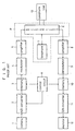
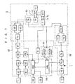
- Fig. 1 is a block diagram of a generic construction of a conventional apparatus for transmitting and receiving signals in the video phone employing the telephone line.
- the conventional apparatus comprises a camera 1 for taking an image of a caller, an A/D converter 2 for digitizing a video signal outputted from the camera 1, a first memory unit 3 for storing an output signal from the A/D converter 2, a modulator 4 for modulating the signal, or digitized video signal, stored in the first memory unit 3, a first amplifier 5 for amplifying an output signal from the modulator 4 by a predetermined amplification degree, a second amplifier 8 for amplifying a digitized video signal from a counterpart by a predetermined amplification degree, a demodulator 9 for demodulating an output signal from the second amplifier 8, a second memory unit 10 for storing an output signal from the demodulator 9, a D/A converter 11 for converting the signal, or digitized video signal from the counterpart, stored in the second memory unit 10 into an analog signal to output the analog signal,
- the image of the face of the caller, taken by the camera 1, is an analog signal, which is converted by the A/D converter 2 upon receiving a clock from the control circuit 14, into a digital signal to be stored into the first memory unit 3. Also, the control circuit 14 feeds address and control signals to the first memory unit 3. Data stored in the first memory unit 3 is modulated suitably to a line characteristic by the modulator 4 and then is transferred through the first amplifier 5 to the switching circuit 6, which sends the data out over the telephone line, thereby enabling the video signal to be sent to the counterpart.
- the switching circuit 6 transfers the digitized video signal to the second amplifier 8, as a receiving amplifier, and then to the demodulator 9.
- the demodulated signal from the demodulator 9 is stored into the second memory unit 10 under the control of the control circuit 14 and the signal stored in the second memory unit 10 is then converted by the D/A converter 11 into an analog signal to be displayed on the monitor 12.
- the caller can see the face of the counterpart through the monitor.
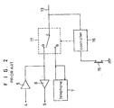
- Fig. 2 is a detailed circuit diagram of a part P including the telephone 7 and the switching circuit 6, shown in Fig. 1.
- a controller 16 upon pushing a transmitting switch 15 under the condition that the caller would like to send his image to the counterpart while caller telephones a message to the counterpart, a controller 16 outputs a control signal to a switch 17.
- the terminal c of the switch 17 is connected to the terminal a in the transmission and reception of the video signal, while to terminal b in the voice telephone call.
- no transmission and reception of the voice signal can be performed under the condition of the transmission and reception of the video signal.
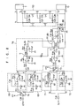
- Fig. 3 is a circuit diagram of an embodiment of the conventional apparatus for transmitting and receiving signals in the video phone employing the telephone line
- the conventional apparatus is shown to comprise a transmitting transformer 18 connected between the standard telephone 13 and telephone 7, for interfacing the video signal to be transmitted, a receiving transformer 19 connected between the standard telephone 13 and telephone 7 for interfacing the video signal to be received, a first video signal processing circuit 20 for processing the video signal to be transmitted, a second video signal processing circuit 21 for processing the video signal to be received, a relay 22 including two relay switches 22a and 22b, for operating to send only one of the voice signal and the video signal via the telephone line 13, and a controller 23 for applying a drive control signal to the relay 22 and the first and the second video signal processing circuits 20 and 21.
- the reference numeral 24 designates a surge voltage absorbing triac, R1 to R7 resistors and C1 to C7 capacitors.
- the controller 23 then operates to control the first video signal processing circuit 20 to send the video signal via the telephone line 13.
- the controller 23 operates to control the second video signal processing circuit 21 to receive the video signal, even in the reception of the video signal from the counterpart. similarly to the case of the transmission of the video signal.
- the conventional apparatus cannot transmit and receive the voice signal simultaneously with the video signal via the single transmission line in the video phone, thereby resulting in the stand-by status of the one side in the course of transmission of the video signal from the other side.
- the transmission and reception of the video signal between the caller and the counterpart by the conventional apparatus as stated above takes too much time.
- EP-A-0 244 260 proposes a method for multiplex transmission of an audio signal and a colour video signal through a communication cable.
- the video signal is separated into a luminance signal and a chrominance signal.
- the luminance signal is frequency modulated on to a luminance carrier while the chrominance signal is down converted to a lower band.
- the modulated luminance carrier, the down converted chrominance signal and the audio signal are multiplexed by frequency division and transmitted.
- the method reduces the bandwidth required for transmitted combined audic and video signals and is resistant to interference from medium wave radio frequency signals.
- a transmitting and receiving method in a video phone apparatus for handling a video signal and a voice signal by means of a single twin pair transmission line, said videophone having a standard telephone having a hook switch, a displaying monitor and a self-camera, a method of transmitting and receiving the voice signal simultaneously with the video signal via the single transmission line, said method comprising the step of passing only voice signals with a frequency region below a first frequency (f1) set within a frequency band of said transmission line by making use of filtering means; characterised in that said method further comprises the steps of:
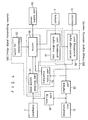
- the apparatus for transmitting and receiving signals in the video phone in accordance with the present invention is shown to comprise a filter 50 connected between a telephone 7 and a telephone line 13, for inputting a voice signal from either telephone 7 or telephone line 13 and passing only voice signal with a frequency region below a first frequency f1 set within a frequency band of the telephone line 13.
- the apparatus comprises a hook switch sensor 51 for sensing ON/OFF states of a hook switch (not shown), a transmitting switch 52 for outputting a control signal for transmission of video signal, an interface unit 53 for separately outputting video signals to be received and transmitted, a frequency discriminator 54 for discriminating if a carrier frequency in the video signal to be received is which of a second frequency f2 or a third frequency f3 set within the frequency band of the telephone line 13 and outputting a acknowledge signal depending upon the discriminated result, a power supply 55 for supplying power required by the apparatus, and a microprocessor 56 for inputting output signals from the hook switch sensor 51, the transmitting switch 52 and the frequency discriminator 54 and outputting a plurality of control signals necessary to the operation of the apparatus.
- the apparatus according to the present invention is also provided with a first and a second video signal processing circuits 57 and 58.
- the first video signal processing circuit 57 inputs the video signal from a self-camera 1 and operates to send the inputted video signal to the counterpart. Namely, the first video signal processing circuit 57 modulates and band-pass filters the inputted video signal by a predetermined frequency in response to the control signal from the microprocessor 56 and outputs such modulated and band-pass filtered video signal to the interface unit 53.
- the second video signal processing circuit 58 operates to display the video signal inputted through the interface unit 53 on a monitor 12. That is, the second video signal processing circuit 58 demodulates and band-pass filters the inputted video signal by a predetermined frequency in response to the control signal from the microprocessor 56 and outputs such demodulated and band-pass filtered video signal to the monitor 12.
- the power-ON/OFF of the whole system is controlled by an output signal from the hook switch sensor 51.
- the output signal from the hook switch sensor 51 allows the microprocessor 56 to drive the power supply 55 to turn on power.
- the microprocessor 56 instructs the power supply 55 to turn off power.
- the microprocessor 56 designates the second frequency f2 as shown in Fig. 5b as the carrier frequency for modulation.
- the video signal from the counterpart can be modulated and transmitted only by the third frequency f3 as shown in Fig. 5b.
- the hook switch sensor With the output signal from the hook switch sensor, it is possible to recognize the end state of the transmission and reception of the image data, or video signal. That is, because the caller hangs up a handset if his telephone call to the counterpart is finished, the hook switch of the telephone 7 is turned on, the state of which is sensed by the hook switch sensor 51, thereby allowing the microprocessor 56 to turn off power. As a result, the image telephone call between them is finished.
- the microprocessor 56 perceives such state from the output signal from the frequency discriminator 54 and designates the third frequency f3 as shown in Fig. 5b as the carrier frequency of the video signal for transmission, since the carrier frequency of the video signal to be received is the second frequency f2 as shown in Fig. 5b.
- one first transmitting the video signal first selects the second frequency f2 as the carrier frequency.
- a video signal transmitting means 100 is shown to include the hook switch sensor 51, the transmitting switch 52, the microprocessor 56 and the first video signal processing circuit 57.
- a video signal receiving means 200 includes the hook switch sensor 51, the frequency discriminator 54, the microprocessor 56 and the second video signal processing circuit 58.
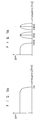
- Fig. 5b illustrates frequency spectrum characteristics of the transmission line according to the present invention.
- the telephone line has the frequency band limited to 3.4 KHz as shown in Fig. 5a.
- the second frequency carrier is designated at 2 KHz part and the third frequency carrier is designated at 2.8 KHz part, so that the voice signal and the video signal can be simultaneously transmitted and received. Therefore, the voice signal and the video signal modulated at the first frequency or the second frequency can be simultaneously seen and heard.
- the microprocessor 56 is shown to include a first microprocessor 56a, as a transmitting microprocessor, for providing a control signal for the first video signal processing circuit 57 and a second microprocessor 56b, as a receiving microprocessor, for providing a control signal for the second video signal processing circuit 58.
- the first video signal processing circuit 57 includes a timing signal generator 61 for generating a clock signal, an A/D converter 62 for inputting the video signal from the self-camera 1 and digitizing the inputted video signal to be transmitted, in response to the clock signal from the timing signal generator 61, a memory controller 63 for generating read/wright select and address signals in response to the control signal from the first microprocessor 56a and the clock signal from the timing signal generator 61, a memory unit 64 for storing the digitized video signal from the A/D converter 62 in an addressed location in response to the read/wright select and address signals from the memory controller 63, a carrier generator 65 for generating the the second frequency f2 carrier or the third frequency f3 carrier as shown in Fig.
- a modulator 66 for modulating the image data, or digitized video signal stored in the memory unit 66 by the frequency carriers generated by the carrier generator 65, a first amplifier 67 for amplifying an output signal from the modulator 66 by a predetermined amplification degree, a first band pass filter 68 for passing only video signal with the second frequency f2 component to the interface unit 53, a second band pass filter 69 for passing only video signal with the third frequency f3 component to the interface unit 53, and a first switching circuit 70 for selectively outputting an output signal from the first amplifier 67 to the first band pass filter 68 or the second band pass filter 69 in response to the control signal from the first microprocessor 56a.
- the second video signal processing circuit 58 includes a third band pass filter 71 for passing only video signal with the second frequency f2 component, a fourth band pass filter 72 for passing only video signal with the third frequency f3 component, a second switching circuit 73 for selectively outputting the video signal from the counterpart, inputted through the interface unit 53, to the third band pass filter 71 or the fourth band pass filter 72 in response to the control signal from the second microprocessor 56b, a second amplifier 74 for amplifying the video signal from the counterpart, passed through the third band pass filter 71 or the fourth band pass filter 72, by a predetermined amplification degree, a demodulator 75 for inputting an output signal from the second amplifier 74 and demodulating the inputted signal in response to the control signal from the second microprocessor 56b, and a D/A converter 76 for converting an output signal from the demodulator 75 into an analog signal and outputting the analog signal to the displaying monitor 12.
- a third band pass filter 71 for passing only video signal with the second frequency f2 component
- the interface unit 53 also includes a transmitting and receiving transformer 77 adapted for inputting and outputting simultaneously the video signals to be transmitted and received and a hybrid circuit 78 adapted for separately outputting the video signals to be received and transmitted, inputted through the transmitting and receiving transformer 77.
- the frequency discriminator 54 is also provided with two tone decoders 54a and 54b for discriminating the frequency component of the video signal from the counterpart.
- the first microprocessor 56a for transmission outputs the control signal to the power supply 55 to turn on it.
- the A/D converter 62 then converts the video signal outputted from the self-camera 1 into a digital signal in response to the clock signal supplied from the timing signal generator 61.
- the video signal digitized by the A/D converter 62 is stored in the location of the memory unit 64 corresponding to a predetermined address under the control of the memory controller 63, which generates the address signal and the read/wright select signals.
- the first microprocessor 56a for transmission designates the second frequency f2 as the carrier signal from the carrier generator 65, so that an output signal from the memory unit 64, or the digitized video signal stored in the memory unit 64 can be modulated by the carrier of the second frequency f2 component by the modulator 66.
- the modulated video signal to be transmitted is amplified by the predetermined amplification degree by the first amplifier 67 and then transferred to the first band pass filter 68 by the switching operation of the first switching circuit 70, the switching control of which is performed by the first microprocessor 56a for transmission.
- the modulated video signal is filtered by the first band pass filter 68 allowing only second frequency f2 component to be inputted by the interface unit 53, and then sent to the counterpart via the telephone line 13. Simultaneously, the video signal sent from the counterpart is inputted through the same interface unit 53.
- the second microprocessor 56b perceives whether the frequency component received is the second frequency f2 or the third frequency f3 in accordance with output signals from the tone decoders 54a and 54b in the frequency discriminator 54 and then controls the second switching circuit 73 for frequency selection in accordance with the discriminated result.
- the video signal is inputted to the third band pass filter 71; if the carrier of the video signal received is the third frequency f3 component, the video signal is inputted to the fourth band pass filter 72.
- the video signal filtered in accordance with the frequency component as mentioned above is amplified by the predetermined amplification degree by the second amplifier 74, demodulated by the demodulator 75 under the control of the second microprocessor 56b and then converted into an analog signal by the D/A converter 76. In result, this analog signal, or video signal is displayed on the monitor 12.
- Fig. 8 is a detailed circuit diagram of a part Q in Fig. 7.
- the reference numerals R11 to R24 designate resistors, C11 to C33 capacitors, 81 to 86 operational amplifiers, 88 triac, K1 to K4 variable resistors and 90 switch.
- the first microprocessor 56a for transmission of video signal outputs a control signal all for driving the first switching circuit 70, so that the output signal from the firs-t amplifier 67 can be passed through the first band pass filter 68. Namely, the video signal to be transmitted with the second frequency f2 component is outputted to a point r.
- the variable resistor K3 connected to the operational amplifier 83 in the hybrid circuit 78 is adjusted to adjust a signal at a point s.
- the phase of the video signal is once inverted by the operational amplifier 83 and again inverted by the operational amplifier84 .
- the video signal is sent out over the telephone line 13 by the transmitting and receiving transformer 77.
- the voice signal being transmitted and received is passed through the filter 50 connected to the telephone 7, thereby allowing only voice signal with frequency component below the first frequency f1 to be filtered. Therefore, the voice and video signals can be simultaneously sent via the telephone line 13.
- variable resistor K3 is adjusted such that the sum of the video signals at the point s, or output of the operational amplifier 83, and at the point t, or output of the operational amplifier 84, can become zero. Therefore, the video signal transmitted can be never received reversely.
- the video signal sent from the counterpart is not inputted to the operational amplifiers 83 and 84, but to the second switching circuit 73 via the operational amplifier 85, from the transmitting and receiving transformer 77.
- the switching circuit 73 is switched by a control signal a12 from the second microprocessor 56b to transfer the video signal to be received, to the third band pass filter 71. That is, if the video signal to be transmitted is to have the second frequency f2 component, thus the video signal to be received is to have the third frequency f3 component.
- the apparatus in accordance with the present invention can provide advantages as follows:
- the transmission time can be shorted by the simultaneous transmission and reception of the video signal between the caller and the counterpart.
Claims (2)
- Ein Sende- und Empfangsverfahren in einem Video-Telefongerät zur Behandlung eines Video-Signals und Voice-Signals mittels einer einzigen zweiadrigen Sendeleitung (13), wobei das Videotelefon ein Standardtelefon mit einem Gabelumschalter aufweist, ein Anzeigemonitor (12), und eine Selbstkamera (1), ein Verfahren zum Senden und Empfangen eines Voice-Signals gleichzeitig mit dem Video-Signal über die einzige Sendeleitung (13), wobei das Verfahren den Schritt der Weitergabe nur von Voice-Signalen umfaßt, mit einem Frequenzbereich unterhalb einer ersten Frequenz (f1), die innerhalb eines Frequenzbandes der Sendeleitung durch Verwendung von Filtermitteln gesetzt wird;
dadurch gekennzeichnet, daß das Verfahren weiterhin die Schritte umfaßt:das Einschalten der Stromzufuhr, wenn der Gabelumschalter des Telefons von einem ursprünglichen EIN-Zustand in einen AUSZustand geschaltet wird;die Bestimmung einer zweiten Frequenz (f2), die innerhalb des Frequenzbandes der Sendeleitung (13) als eine Trägerfrequenz des Video-Signals zum Senden gesetzt wird, und einer dritten Frequenz (f3), die innerhalb des Frequenzbandes der Sendeleitung (13) als Trägerfrequenz des Video-Signals zum Empfang gesetzt wird, beim Empfangen eines Steuersignals zum Senden des Video-Signals; die Frequenz-Modulation und -Demodulation der zu sendenden und zu empfangenden Video-Signale in Übereinstimmung mit den bestimmten Frequenzen; das Senden und Empfangen der modulierten und demodulierten Video-Signale; und das Ausschalten des Stromes nachdem das Senden der modulierten und demodulierten Video-Signale beendet ist;die Bestimmung der anderen der zweiten Frequenz (f2) und der dritten Frequenz (f3) als Trägerfrequenz des Video-Signals zum Senden, beim Empfang des Video-Signals mit einer der zweiten Frequenz (f2) und der dritten Frequenz (f3) von einer Gegenstelle und bei keinem Steuersignal zum Senden des Video-Signals; die Modulation und Demodulation der zu sendenden und zu empfangendenVideo-Signale in Übereinstimmung mit den bestimmten Frequenzen; das Senden und Empfangen der modulierten und demodulierten Video-Signale bis der Gabelumschalter in den EIN-Zustand geschaltet wird; und das Ausschalten des Stromes nachdem das Senden des modulierten und demodulierten Video-Signals beendet ist; unddie Durchführung nur eines Voice-Telefonanrufs, wenn weder das Steuersignal zum Senden des Video-Signals noch das Video-Signal vor der Gegenstelle empfangen wird. - Das Sende- und Empfangsverfahren nach Anspruch 1, dadurch gekennzeichnet, daß die erste, zweite und dritte Frequenz durch die unten stehende Gleichung definiert werden:
 f1 die erste Frequenzf2 die zweite Frequenzf3 die dritte Frequenzfx die Grenzfrequenz der Sendeleitung (13) ist.
Applications Claiming Priority (4)
| Application Number | Priority Date | Filing Date | Title |
|---|---|---|---|
| KR1019900007361A KR920010785B1 (ko) | 1990-05-22 | 1990-05-22 | 영상과 음성 동시 전송장치 |
| KR736190 | 1990-05-22 | ||
| KR1019900011651A KR930009873B1 (ko) | 1990-07-31 | 1990-07-31 | 전이중 통신용 전화기 |
| KR1165190 | 1990-07-31 |
Publications (3)
| Publication Number | Publication Date |
|---|---|
| EP0458523A2 EP0458523A2 (de) | 1991-11-27 |
| EP0458523A3 EP0458523A3 (en) | 1993-05-26 |
| EP0458523B1 true EP0458523B1 (de) | 1997-04-16 |
Family
ID=26628249
Family Applications (1)
| Application Number | Title | Priority Date | Filing Date |
|---|---|---|---|
| EP91304386A Expired - Lifetime EP0458523B1 (de) | 1990-05-22 | 1991-05-16 | Verfahren und Gerät zur Übertragung und zum Empfangen von Signalen in einem Bildtelefon |
Country Status (4)
| Country | Link |
|---|---|
| US (1) | US5204893A (de) |
| EP (1) | EP0458523B1 (de) |
| JP (1) | JP2627688B2 (de) |
| DE (1) | DE69125646T2 (de) |
Families Citing this family (15)
| Publication number | Priority date | Publication date | Assignee | Title |
|---|---|---|---|---|
| US5550649A (en) * | 1992-05-14 | 1996-08-27 | Current Logic Systems, Inc. | Multi-function telecommunications instrument |
| US5541640A (en) * | 1992-06-23 | 1996-07-30 | Larson; Craig R. | Videophone for simultaneous audio and video communication via a standard telephone line |
| CA2108872C (en) * | 1993-01-28 | 1997-09-16 | David B. Smith | Audio/video telephone communications |
| JP3290231B2 (ja) * | 1993-03-02 | 2002-06-10 | 株式会社日立製作所 | 音声画像通信装置 |
| DE19519167A1 (de) * | 1995-05-24 | 1996-11-28 | Deutsche Telekom Ag | Verfahren und Anordnung zur verbesserten Informationsübertragung mittels Fax-Endgerät |
| US5760824A (en) * | 1995-12-29 | 1998-06-02 | Lucent Technologies Inc. | Multimedia telephone having wireless camera and television module and method of operation thereof |
| US5703636A (en) * | 1996-05-14 | 1997-12-30 | Cifaldi; Carmine | High resolution optical communication system |
| AU5205398A (en) * | 1997-02-28 | 1998-09-03 | Motorola, Inc. | Method and apparatus for removing video signal distribution in a video telephony system |
| FI106910B (fi) | 1998-09-15 | 2001-04-30 | Nokia Networks Oy | Yhtaikaisten puhelujen toteuttaminen tietoliikenneverkossa |
| US6201562B1 (en) | 1998-10-31 | 2001-03-13 | Kar-Wing E. Lor | Internet protocol video phone adapter for high bandwidth data access |
| GB0011747D0 (en) * | 2000-05-17 | 2000-07-05 | Butterworth Martyn | Improvements related to telecoms |
| KR20010113398A (ko) * | 2000-06-19 | 2001-12-28 | 구자홍 | 다기능 냉장고 |
| JP2002094928A (ja) * | 2000-09-11 | 2002-03-29 | Canon Inc | 画像記録装置、画像データ通信時処理方法及び記憶媒体 |
| US20070076095A1 (en) * | 2005-10-03 | 2007-04-05 | Tomaszewski Olga D | Video Monitoring System Incorporating Cellular Phone Technology |
| KR100813010B1 (ko) * | 2006-11-09 | 2008-03-13 | (주)링스텔레콤 | 반이중 방식으로 영상 신호를 송신하고 전이중 방식으로음성 및 데이터 신호를 전송하는 방법 및 그 방법을 이용한신호 전송용 모뎀 |
Family Cites Families (9)
| Publication number | Priority date | Publication date | Assignee | Title |
|---|---|---|---|---|
| US3873771A (en) * | 1972-04-11 | 1975-03-25 | Telescan Communications System | Simultaneous transmission of a video and an audio signal through an ordinary telephone transmission line |
| US4481622A (en) * | 1982-04-01 | 1984-11-06 | Anderson Jacobson, Inc. | High speed dial-up telephone circuit full duplex data transmission techniques |
| DE3242028A1 (de) * | 1982-11-13 | 1984-05-17 | Standard Elektrik Lorenz Ag, 7000 Stuttgart | Kabelfernsehsystem |
| US4701946A (en) * | 1984-10-23 | 1987-10-20 | Oliva Raymond A | Device for controlling the application of power to a computer |
| GB2173675A (en) * | 1985-03-22 | 1986-10-15 | Steven Henry Lerman | Communication system |
| DE3786946T2 (de) * | 1986-04-30 | 1994-01-27 | Sharp Kk | Verfahren und System für Multiplexübertragung eines Audiosignals und eines Videosignals über ein Kommunikationskabel. |
| DE3801116A1 (de) * | 1988-01-16 | 1989-07-27 | Bosch Gmbh Robert | Verfahren und vorrichtung zur gemeinsamen uebertragung von digitalisierten fernseh-, ton- und datensignalen |
| US4849811A (en) * | 1988-07-06 | 1989-07-18 | Ben Kleinerman | Simultaneous audio and video transmission with restricted bandwidth |
| JPH02257783A (ja) * | 1989-03-30 | 1990-10-18 | Mitsubishi Electric Corp | 静止画テレビ電話伝送方式 |
-
1991
- 1991-05-16 EP EP91304386A patent/EP0458523B1/de not_active Expired - Lifetime
- 1991-05-16 DE DE69125646T patent/DE69125646T2/de not_active Expired - Fee Related
- 1991-05-22 US US07/703,916 patent/US5204893A/en not_active Expired - Lifetime
- 1991-05-22 JP JP3145316A patent/JP2627688B2/ja not_active Expired - Fee Related
Also Published As
| Publication number | Publication date |
|---|---|
| DE69125646D1 (de) | 1997-05-22 |
| JPH04230191A (ja) | 1992-08-19 |
| DE69125646T2 (de) | 1997-10-23 |
| EP0458523A3 (en) | 1993-05-26 |
| EP0458523A2 (de) | 1991-11-27 |
| US5204893A (en) | 1993-04-20 |
| JP2627688B2 (ja) | 1997-07-09 |
Similar Documents
| Publication | Publication Date | Title |
|---|---|---|
| EP0458523B1 (de) | Verfahren und Gerät zur Übertragung und zum Empfangen von Signalen in einem Bildtelefon | |
| US5493698A (en) | Radio apparatus for simulataneously transmitting and receiving signals using a simple frequency | |
| US5423060A (en) | Method of remote-registering communication control information and circuitry therefor | |
| EP0416598A2 (de) | Faksimilegerät | |
| US5722054A (en) | Communication apparatus | |
| JP3726372B2 (ja) | ドアホン装置 | |
| US6115414A (en) | System for setting up a wireless connection for exchanging information with another system, which system is provided with a transceiver device for transmitting and receiving information in a wireless manner, and also modulator/demodulator device | |
| US5226072A (en) | Facsimile machine having recording/reproducing apparatus | |
| JP2865293B2 (ja) | テレビ電話装置 | |
| JP3584648B2 (ja) | テレビインターホンシステム | |
| JPH03217187A (ja) | 静止画像伝送装置 | |
| JP2798519B2 (ja) | ファクシミリ装置 | |
| KR100189247B1 (ko) | 전원선을 통한 음성 통화장치 | |
| JP2634443B2 (ja) | モニタ付きインターホン装置 | |
| JP2863327B2 (ja) | ホームテレホンシステム | |
| JP3018624B2 (ja) | 無線通信システム | |
| JPH0226169A (ja) | ファクシミリ装置 | |
| JPH0621879A (ja) | コードレス電話装置 | |
| JPH03270559A (ja) | ファクシミリ装置 | |
| JPH07135537A (ja) | 画像送信装置 | |
| JPH01300689A (ja) | 伝送装置 | |
| JPS61263360A (ja) | フアクシミリアダブタ | |
| JPS6336673A (ja) | フアクシミリ装置 | |
| JPH01213059A (ja) | 静止画送信装置付電話機 | |
| JPH04107957U (ja) | 電燈線搬送通信方式のインターホン装置 |
Legal Events
| Date | Code | Title | Description |
|---|---|---|---|
| PUAI | Public reference made under article 153(3) epc to a published international application that has entered the european phase |
Free format text: ORIGINAL CODE: 0009012 |
|
| AK | Designated contracting states |
Kind code of ref document: A2 Designated state(s): DE FR GB |
|
| PUAL | Search report despatched |
Free format text: ORIGINAL CODE: 0009013 |
|
| AK | Designated contracting states |
Kind code of ref document: A3 Designated state(s): DE FR GB |
|
| 17P | Request for examination filed |
Effective date: 19930805 |
|
| 17Q | First examination report despatched |
Effective date: 19950824 |
|
| GRAG | Despatch of communication of intention to grant |
Free format text: ORIGINAL CODE: EPIDOS AGRA |
|
| GRAH | Despatch of communication of intention to grant a patent |
Free format text: ORIGINAL CODE: EPIDOS IGRA |
|
| RAP1 | Party data changed (applicant data changed or rights of an application transferred) |
Owner name: LG ELECTRONICS INC. |
|
| GRAH | Despatch of communication of intention to grant a patent |
Free format text: ORIGINAL CODE: EPIDOS IGRA |
|
| GRAA | (expected) grant |
Free format text: ORIGINAL CODE: 0009210 |
|
| AK | Designated contracting states |
Kind code of ref document: B1 Designated state(s): DE FR GB |
|
| REF | Corresponds to: |
Ref document number: 69125646 Country of ref document: DE Date of ref document: 19970522 |
|
| ET | Fr: translation filed | ||
| PLBE | No opposition filed within time limit |
Free format text: ORIGINAL CODE: 0009261 |
|
| STAA | Information on the status of an ep patent application or granted ep patent |
Free format text: STATUS: NO OPPOSITION FILED WITHIN TIME LIMIT |
|
| 26N | No opposition filed | ||
| REG | Reference to a national code |
Ref country code: GB Ref legal event code: IF02 |
|
| PGFP | Annual fee paid to national office [announced via postgrant information from national office to epo] |
Ref country code: GB Payment date: 20060510 Year of fee payment: 16 |
|
| PGFP | Annual fee paid to national office [announced via postgrant information from national office to epo] |
Ref country code: DE Payment date: 20060511 Year of fee payment: 16 |
|
| PGFP | Annual fee paid to national office [announced via postgrant information from national office to epo] |
Ref country code: FR Payment date: 20060515 Year of fee payment: 16 |
|
| GBPC | Gb: european patent ceased through non-payment of renewal fee |
Effective date: 20070516 |
|
| REG | Reference to a national code |
Ref country code: FR Ref legal event code: ST Effective date: 20080131 |
|
| PG25 | Lapsed in a contracting state [announced via postgrant information from national office to epo] |
Ref country code: DE Free format text: LAPSE BECAUSE OF NON-PAYMENT OF DUE FEES Effective date: 20071201 |
|
| PG25 | Lapsed in a contracting state [announced via postgrant information from national office to epo] |
Ref country code: GB Free format text: LAPSE BECAUSE OF NON-PAYMENT OF DUE FEES Effective date: 20070516 |
|
| PG25 | Lapsed in a contracting state [announced via postgrant information from national office to epo] |
Ref country code: FR Free format text: LAPSE BECAUSE OF NON-PAYMENT OF DUE FEES Effective date: 20070531 |