EP0457739B1 - Apparatus for measuring a length of elongated materials, such as cables - Google Patents
Apparatus for measuring a length of elongated materials, such as cables Download PDFInfo
- Publication number
- EP0457739B1 EP0457739B1 EP91850087A EP91850087A EP0457739B1 EP 0457739 B1 EP0457739 B1 EP 0457739B1 EP 91850087 A EP91850087 A EP 91850087A EP 91850087 A EP91850087 A EP 91850087A EP 0457739 B1 EP0457739 B1 EP 0457739B1
- Authority
- EP
- European Patent Office
- Prior art keywords
- marking
- belts
- measuring station
- measuring
- unit
- Prior art date
- Legal status (The legal status is an assumption and is not a legal conclusion. Google has not performed a legal analysis and makes no representation as to the accuracy of the status listed.)
- Expired - Lifetime
Links
Images

Classifications
-
- G—PHYSICS
- G01—MEASURING; TESTING
- G01B—MEASURING LENGTH, THICKNESS OR SIMILAR LINEAR DIMENSIONS; MEASURING ANGLES; MEASURING AREAS; MEASURING IRREGULARITIES OF SURFACES OR CONTOURS
- G01B7/00—Measuring arrangements characterised by the use of electric or magnetic techniques
- G01B7/02—Measuring arrangements characterised by the use of electric or magnetic techniques for measuring length, width or thickness
- G01B7/04—Measuring arrangements characterised by the use of electric or magnetic techniques for measuring length, width or thickness specially adapted for measuring length or width of objects while moving
- G01B7/042—Measuring arrangements characterised by the use of electric or magnetic techniques for measuring length, width or thickness specially adapted for measuring length or width of objects while moving for measuring length
Definitions
- the present invention relates to linear measuring apparatus intended for measuring elongated material, such as cables, and comprising a measuring station which includes two endless belts each of which runs over two belt pulleys and between which the material to be measured is drawn, and further comprising sensors connected in the measuring station, and a counter unit which is connected to one of the sensors for indicating the length of said material.
- Linear measuring apparatus which include two mutually opposed endless belts between which the material to be measured is drawn are known to the art.
- the belts are positioned vertically one above the other and the distance between the belts can be adjusted so as to bring the belts into friction abutment with the material such that movement of the material through the measuring apparatus will cause the belts to rotate around their respective pulleys.
- a sensor is connected to one of said belts and also to a counter unit for indicating measured lengths.
- the disadvantage with known linear measuring apparatus of this kind is that the belts cannot be adjusted readily to positions in which the friction generated is sufficiently great to obviate the risk of slipping between material and belts and therewith also the risk of obtaining wrong measurements.
- EP-A1-0 338 932 discloses an apparatus for pulling elongated material, and which also can be used to measure the length of the material, including two endless belts between which the material is pulled.
- the belts are provided with deformable teeth to avoid slipping of the material during pulling.
- the distance between the belts is fixed, which means that elongated materials of different diameter cannot be pulled through the apparatus without first changing the distance to ensure reliable pulling and avoid slipping of the material.
- Linear measuring apparatus with devices for marking the material in selected measured lengths are known to the art.
- JP-A-59-94007 discloses such an apparatus for measuring and marking the length of filamentous bodies.
- a similar apparatus is disclosed in DE-A-26 54 996.
- both these apparatuses are encumbered with the above mentioned drawbacks of lack of measurment accuracy.
- the object of the present invention is to avoid the drawbacks with which earlier known linear measuring apparatus are encumbered and to provide a linear measuring apparatus which is of simple construction and reliable in operation and with which marking of determined lengths can be achieved simply and reliably.
- This object is achieved in that the belts are positioned horizontally side-by-side and in resilient abutment with the material to be measured; in that the sensors are pulse generators each of which is connected to one belt pulley of each endless belt, wherein the pulses generated by the pulse generators are conducted to the counter unit in which the mean value of the generated pulses representative of the material length is calculated.
- a marking unit is arranged downstream of the measuring station and connected to the counter unit for marking the elongated material at selected points on the measured length; and in that a further pulse generator is connected to the other pulley of said one belt, wherein the pulses generated by this further pulse generator are conducted to the marking unit, via said counter unit, for delivering speed information to said marking unit.
- the measuring station preferably comprises a centre arm which is freely pivotable about a centrally mounted, vertical pin, L-shaped outer arms which are pivotally mounted on vertical pivot pins at each end of the centre arm, with the longer legs being substantially parallel with and located horizontally beside the centre arm, each of said longer legs supporting on vertical shafts a respective one of the belt pulleys, and further including spring means which endeavour to draw the outer arms towards one another, wherein the endless belts lie in abutment with one another in the absence of elongated material therebetween.
- the inventive linear linear measuring apparatus affords a number of advantages. For instance, because the belts resiliently abut the material, adequate friction will always be generated between the material and belts, therewith achieving optimum reliability in operation. Furthermore, because sensors are connected to both belts, guiding of the material through the apparatus is not critical. Marking of the material can also be effected with great precision and in a simple fashion, without the speed at which the material is drawn through the apparatus having a negative affect on the result.
- the construction of the measuring station ensures that the station will always be correctly positioned and be in alignment with the direction in which the material is drawn through the apparatus.
- the construction is also simple and purposeful.
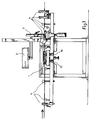
- Figure 1 is a side view of inventive linear measuring apparatus.
- Figure 2 is a top view of a measuring station included in the measuring apparatus.
- Figure 1 is a side view of linear measuring apparatus constructed in accordance with the invention.
- the measuring apparatus is mounted on a table, a stand or the like, and includes a measuring station 1 and a counter unit 2.
- the material to be measured is drawn through the measuring station 1, which is described in more detail below, between two endless belts from the left to the right in the Figure, in the arrowed direction.
- the apparatus is preferably intended for measuring cables and the like and is then placed in the production line upstream of a cable-coiling station.
- the measuring apparatus also includes a marking unit 3 which is connected to the counter unit 2 for marking and indicating lengths of the material at selected measured lengths, optionally combined with the marking of information, for instance the manufacture and type of cable.
- the material is guided through the apparatus by guide rollers 4 which guide the material horizontally through the measuring station 1 and past the marking unit 3, as straight as possible.
- the measuring station 1 includes a belt assembly comprising two endless belts 5a and 5b which extend horizontally, side-by-side, around two respective belt pulleys 6a and 6b.
- the material to be measured is drawn horizontally through the belt assembly, and between the belts with the belts and material in resilient abutment with one another, wherein the friction generated between the material and the belts cause the belts to be driven around said pulleys in the same direction and at the same speed as the material.
- the belts 5a and 5b are preferably toothed belts and the belt pulleys 6a and 6b are sprocket wheels, in order to prevent slipping between the belts and the pulleys and therewith give rise to wrong measurements.
- the belt assembly is mounted on an arrangement which comprises a centre arm 7 which is freely pivotal about a centrally located vertical pin 8.
- An outer L-shaped arm 9 is pivotally mounted on vertically extending pins 10 at each end of the arm 7.
- Vertical shafts 11 which carry respective pulleys 6a and 6b are rotatably mounted on the longer legs 9a of the outer L-shaped arms 9.
- the legs 9a extend substantially parallel with and by the side of the centre arm 7 and are drawn in towards the centre arm by spring means 12, so that the endless belts 5a and 5b will abut one another in the absence of material therebetween.
- the spring means 12 ensures that the requisite degree of friction is generated between the belts and the material as the material is drawn through the belt assembly.
- the pivotal motion of the belt assembly around the central pin 8 causes the assembly to adjust to the direction in which the material is drawn, so that no lateral forces will act on the endless belts and give rise to an erroneous measuring result.
- the material passing through the apparatus is measured with the aid of pulse generators 13 and 14 mounted beneath the measuring station, as clearly shown in Figure 1, and constructed to generate a given number of pulses with each revolution of the belts.
- pulse generators 13 are connected to one shaft 11 of each respective pulley 6a and 6b.
- the pulses produced by the pulse generators are delivered to the counter unit 2 where they are added together and, subsequent to converting the pulses to length measurements, the mean value of the delivered pulses is presented on a counter display as the measured length.
- the pulse generator 14 is connected to the other shaft 11 of one of the pulleys 6a or 6b and the pulses generated thereby are used to supply to the counter unit 2 information relating to the speed at which the material is drawn through the measuring station 1.
- the counter unit sends an initiating pulse to the marking unit 3, causing the marking unit to mark the material in said predetermined lengths, and optionally also to mark the material with additional information, such as information relating to manufacture, type, etc.
- the marking unit is preferably an ink jet printer.
- the speed information obtained from the pulse generator 14 is utilized to correct movement of the material from the measuring station 1 at the moment of measuring the predetermined length to the marking unit 3 at the time of marking said length, so that marking is effected at the correct location.
- the counter unit 2 is preferably a "forwards-backwards"-counter which when the material is drawn back through the measuring station 1 subtracts the pulses generated by the pulse generators 13 in the counter unit. In this case, no initiation pulse will be sent to the marking unit 3 from the counter unit until the material has again been drawn forwards through the measuring station and the predetermined length measurement has again been indicated in said station.
- the counter unit 2 also includes control buttons for setting the counter mechanism to zero, reprogramming the text printed by the marking unit and similar operations, and also with outputs to external counter mechanisms, external speed metres and the like. It is also possible to change or reprogram the marking intervals, for instance each metre of length, each alternate metre of length, etc., and it is also possible to calibrate the counter unit by drawing a gauge through the apparatus.
Landscapes
- Physics & Mathematics (AREA)
- General Physics & Mathematics (AREA)
- Length Measuring Devices With Unspecified Measuring Means (AREA)
- Length Measuring Devices By Optical Means (AREA)
Applications Claiming Priority (2)
| Application Number | Priority Date | Filing Date | Title |
|---|---|---|---|
| SE9001790A SE466276B (sv) | 1990-05-17 | 1990-05-17 | Laengdmaetningsutrustning foer maetning av laangstraeckt material, saasom kablar |
| SE9001790 | 1990-05-17 |
Publications (2)
| Publication Number | Publication Date |
|---|---|
| EP0457739A1 EP0457739A1 (en) | 1991-11-21 |
| EP0457739B1 true EP0457739B1 (en) | 1994-08-31 |
Family
ID=20379519
Family Applications (1)
| Application Number | Title | Priority Date | Filing Date |
|---|---|---|---|
| EP91850087A Expired - Lifetime EP0457739B1 (en) | 1990-05-17 | 1991-04-05 | Apparatus for measuring a length of elongated materials, such as cables |
Country Status (7)
| Country | Link |
|---|---|
| US (1) | US5067248A (fi) |
| EP (1) | EP0457739B1 (fi) |
| DE (1) | DE69103674T2 (fi) |
| DK (1) | DK0457739T3 (fi) |
| FI (1) | FI99161C (fi) |
| NO (1) | NO303301B1 (fi) |
| SE (1) | SE466276B (fi) |
Cited By (1)
| Publication number | Priority date | Publication date | Assignee | Title |
|---|---|---|---|---|
| CN100442075C (zh) * | 2003-02-20 | 2008-12-10 | 雷西昂公司 | 电长度匹配的方法和系统 |
Families Citing this family (4)
| Publication number | Priority date | Publication date | Assignee | Title |
|---|---|---|---|---|
| US5317812A (en) * | 1992-03-06 | 1994-06-07 | Artos Engineering | Wire feeding and measuring apparatus |
| FR2691800B1 (fr) * | 1992-05-27 | 1996-05-03 | Michel Deflou | Dispositif de mesure de longueur de produits longs en defilement. |
| JP5207419B2 (ja) * | 2009-03-13 | 2013-06-12 | 日本たばこ産業株式会社 | テープ検査装置 |
| CN104370160A (zh) * | 2013-08-12 | 2015-02-25 | 泰科电子公司 | 丝线供给长度控制方法和丝线供给长度检测系统 |
Family Cites Families (10)
| Publication number | Priority date | Publication date | Assignee | Title |
|---|---|---|---|---|
| GB756153A (en) * | 1953-04-21 | 1956-08-29 | Eric Barnaby Smith | Improvements in measuring apparatus, more particularly for electric cables and wires |
| GB824482A (en) * | 1955-01-13 | 1959-12-02 | Henleys Telegraph Works Co Ltd | Improvements in or relating to apparatus for measuring the length of filamentary bodies, such as cables |
| DE2446128A1 (de) * | 1974-09-27 | 1976-04-15 | Monforts Fa A | Vorrichtung zum laengenmessen von stoffbahnen |
| US4041610A (en) * | 1975-02-14 | 1977-08-16 | Sumitomo Electric Industries, Ltd. | Apparatus for precise measurement of the length of long length materials |
| DE2654996A1 (de) * | 1976-12-01 | 1978-06-08 | Siemens Ag | Laengenmess- und -markiervorrichtung fuer langgestrecktes gut |
| DE2757363C2 (de) * | 1977-12-20 | 1982-06-24 | Siemens AG, 1000 Berlin und 8000 München | Verfahren zur Längenbestimmung von fadenförmigen Gut |
| JPS5855801A (ja) * | 1981-09-30 | 1983-04-02 | Showa Electric Wire & Cable Co Ltd | 電線自動計尺装置 |
| JPS5994007A (ja) * | 1982-11-22 | 1984-05-30 | Showa Electric Wire & Cable Co Ltd | 長さ表示印刷装置 |
| GB2154000B (en) * | 1984-02-06 | 1987-09-30 | Beta Instr Co | Measuring speed and/or length of elongate material |
| FR2630418A1 (fr) * | 1988-04-22 | 1989-10-27 | Neyret Guy | Dispositif d'entrainement par traction d'un materiau long a section sensiblement constante |
-
1990
- 1990-05-17 SE SE9001790A patent/SE466276B/sv not_active IP Right Cessation
-
1991
- 1991-04-05 DE DE69103674T patent/DE69103674T2/de not_active Expired - Fee Related
- 1991-04-05 DK DK91850087.7T patent/DK0457739T3/da active
- 1991-04-05 EP EP91850087A patent/EP0457739B1/en not_active Expired - Lifetime
- 1991-04-26 US US07/691,799 patent/US5067248A/en not_active Expired - Lifetime
- 1991-05-14 FI FI912337A patent/FI99161C/fi not_active IP Right Cessation
- 1991-05-14 NO NO911871A patent/NO303301B1/no not_active Application Discontinuation
Cited By (1)
| Publication number | Priority date | Publication date | Assignee | Title |
|---|---|---|---|---|
| CN100442075C (zh) * | 2003-02-20 | 2008-12-10 | 雷西昂公司 | 电长度匹配的方法和系统 |
Also Published As
| Publication number | Publication date |
|---|---|
| DK0457739T3 (da) | 1995-01-09 |
| FI912337A (fi) | 1991-11-18 |
| SE466276B (sv) | 1992-01-20 |
| SE9001790L (sv) | 1991-11-18 |
| FI99161B (fi) | 1997-06-30 |
| SE9001790D0 (sv) | 1990-05-17 |
| NO303301B1 (no) | 1998-06-22 |
| US5067248A (en) | 1991-11-26 |
| DE69103674D1 (de) | 1994-10-06 |
| DE69103674T2 (de) | 1995-01-12 |
| EP0457739A1 (en) | 1991-11-21 |
| NO911871D0 (no) | 1991-05-14 |
| NO911871L (no) | 1991-11-18 |
| FI99161C (fi) | 1997-10-10 |
| FI912337A0 (fi) | 1991-05-14 |
Similar Documents
| Publication | Publication Date | Title |
|---|---|---|
| FI83818B (fi) | Anordning foer avvaegd dosering av granulaera eller pulverformiga produkter. | |
| EP0522640A1 (en) | Screen printing device with continuous registering of rotating stencils | |
| KR100395583B1 (ko) | 음식물 반죽을 공급하기 위한 장치 | |
| KR20210090596A (ko) | 굽힘 기계 내에서 가공물의 전진량을 측정하기 위한 측정 유닛 | |
| EP0457739B1 (en) | Apparatus for measuring a length of elongated materials, such as cables | |
| EP1215149A1 (en) | Speed matching system for a web splicer mechanism in a web-fed printing press or the like | |
| US5245760A (en) | Cloth measuring apparatus | |
| US5065527A (en) | Length measuring and positive drive apparatus | |
| US6209866B1 (en) | Document alignment system | |
| JP2000327197A (ja) | ウェブ切断装置および方法 | |
| JPH10104095A (ja) | トルク測定装置 | |
| US4171575A (en) | Actual sew length measuring device | |
| ES8204388A1 (es) | Perfeccionamientos en maquinas bobinadoras para arrollar ma-terial en forma de cordon sobre un carrete | |
| CN213316268U (zh) | 一种辊棒跳动检测分选设备 | |
| US4201145A (en) | Sew length control and measuring apparatus | |
| KR102263600B1 (ko) | 철근의 절단길이 맞춤 방법 | |
| CN216272465U (zh) | 配动力转盘的自动计长送料机 | |
| ES2368816T3 (es) | Procedimiento y dispositivo para la producción de una masa fundida de plástico, cargada con fibra. | |
| GB2171508A (en) | Apparatus for sensing movement | |
| SU896406A1 (ru) | Устройство дл измерени площади плоских материалов | |
| SU856849A2 (ru) | Устройство дл наложени протектора ленточкой | |
| CA2023137C (en) | Method of and apparatus for metering an elongate stringer chain | |
| JPH034509Y2 (fi) | ||
| KR20040110421A (ko) | 체인 컨베이어의 신율측정장치 | |
| JP2540160B2 (ja) | 包装袋用合成樹脂フィルムの印刷ピッチ測定装置 |
Legal Events
| Date | Code | Title | Description |
|---|---|---|---|
| PUAI | Public reference made under article 153(3) epc to a published international application that has entered the european phase |
Free format text: ORIGINAL CODE: 0009012 |
|
| AK | Designated contracting states |
Kind code of ref document: A1 Designated state(s): CH DE DK FR GB LI |
|
| 17P | Request for examination filed |
Effective date: 19920403 |
|
| 17Q | First examination report despatched |
Effective date: 19930714 |
|
| GRAA | (expected) grant |
Free format text: ORIGINAL CODE: 0009210 |
|
| AK | Designated contracting states |
Kind code of ref document: B1 Designated state(s): CH DE DK FR GB LI |
|
| REF | Corresponds to: |
Ref document number: 69103674 Country of ref document: DE Date of ref document: 19941006 |
|
| ET | Fr: translation filed | ||
| REG | Reference to a national code |
Ref country code: DK Ref legal event code: T3 |
|
| PLBE | No opposition filed within time limit |
Free format text: ORIGINAL CODE: 0009261 |
|
| STAA | Information on the status of an ep patent application or granted ep patent |
Free format text: STATUS: NO OPPOSITION FILED WITHIN TIME LIMIT |
|
| 26N | No opposition filed | ||
| REG | Reference to a national code |
Ref country code: GB Ref legal event code: IF02 |
|
| PGFP | Annual fee paid to national office [announced via postgrant information from national office to epo] |
Ref country code: GB Payment date: 20050330 Year of fee payment: 15 |
|
| PGFP | Annual fee paid to national office [announced via postgrant information from national office to epo] |
Ref country code: FR Payment date: 20050418 Year of fee payment: 15 |
|
| PGFP | Annual fee paid to national office [announced via postgrant information from national office to epo] |
Ref country code: CH Payment date: 20050421 Year of fee payment: 15 |
|
| PGFP | Annual fee paid to national office [announced via postgrant information from national office to epo] |
Ref country code: DK Payment date: 20050425 Year of fee payment: 15 |
|
| PGFP | Annual fee paid to national office [announced via postgrant information from national office to epo] |
Ref country code: DE Payment date: 20050531 Year of fee payment: 15 |
|
| PG25 | Lapsed in a contracting state [announced via postgrant information from national office to epo] |
Ref country code: GB Free format text: LAPSE BECAUSE OF NON-PAYMENT OF DUE FEES Effective date: 20060405 |
|
| PG25 | Lapsed in a contracting state [announced via postgrant information from national office to epo] |
Ref country code: LI Free format text: LAPSE BECAUSE OF NON-PAYMENT OF DUE FEES Effective date: 20060430 Ref country code: CH Free format text: LAPSE BECAUSE OF NON-PAYMENT OF DUE FEES Effective date: 20060430 |
|
| PG25 | Lapsed in a contracting state [announced via postgrant information from national office to epo] |
Ref country code: DK Free format text: LAPSE BECAUSE OF NON-PAYMENT OF DUE FEES Effective date: 20060501 |
|
| PG25 | Lapsed in a contracting state [announced via postgrant information from national office to epo] |
Ref country code: DE Free format text: LAPSE BECAUSE OF NON-PAYMENT OF DUE FEES Effective date: 20061101 |
|
| REG | Reference to a national code |
Ref country code: DK Ref legal event code: EBP |
|
| REG | Reference to a national code |
Ref country code: CH Ref legal event code: PL |
|
| GBPC | Gb: european patent ceased through non-payment of renewal fee |
Effective date: 20060405 |
|
| REG | Reference to a national code |
Ref country code: FR Ref legal event code: ST Effective date: 20061230 |
|
| PG25 | Lapsed in a contracting state [announced via postgrant information from national office to epo] |
Ref country code: FR Free format text: LAPSE BECAUSE OF NON-PAYMENT OF DUE FEES Effective date: 20060502 |