EP0456870A1 - Dispositif pour le traitement et/ou le nettoyage chimique des matériels, notamment des plaques à circuits imprimés aux trous ainsi que procédé de ce traitement - Google Patents
Dispositif pour le traitement et/ou le nettoyage chimique des matériels, notamment des plaques à circuits imprimés aux trous ainsi que procédé de ce traitement Download PDFInfo
- Publication number
- EP0456870A1 EP0456870A1 EP90109413A EP90109413A EP0456870A1 EP 0456870 A1 EP0456870 A1 EP 0456870A1 EP 90109413 A EP90109413 A EP 90109413A EP 90109413 A EP90109413 A EP 90109413A EP 0456870 A1 EP0456870 A1 EP 0456870A1
- Authority
- EP
- European Patent Office
- Prior art keywords
- surge
- section
- liquid
- arrangement according
- suction
- Prior art date
- Legal status (The legal status is an assumption and is not a legal conclusion. Google has not performed a legal analysis and makes no representation as to the accuracy of the status listed.)
- Withdrawn
Links
Images

Classifications
-
- C—CHEMISTRY; METALLURGY
- C23—COATING METALLIC MATERIAL; COATING MATERIAL WITH METALLIC MATERIAL; CHEMICAL SURFACE TREATMENT; DIFFUSION TREATMENT OF METALLIC MATERIAL; COATING BY VACUUM EVAPORATION, BY SPUTTERING, BY ION IMPLANTATION OR BY CHEMICAL VAPOUR DEPOSITION, IN GENERAL; INHIBITING CORROSION OF METALLIC MATERIAL OR INCRUSTATION IN GENERAL
- C23G—CLEANING OR DE-GREASING OF METALLIC MATERIAL BY CHEMICAL METHODS OTHER THAN ELECTROLYSIS
- C23G1/00—Cleaning or pickling metallic material with solutions or molten salts
-
- H—ELECTRICITY
- H05—ELECTRIC TECHNIQUES NOT OTHERWISE PROVIDED FOR
- H05K—PRINTED CIRCUITS; CASINGS OR CONSTRUCTIONAL DETAILS OF ELECTRIC APPARATUS; MANUFACTURE OF ASSEMBLAGES OF ELECTRICAL COMPONENTS
- H05K3/00—Apparatus or processes for manufacturing printed circuits
- H05K3/22—Secondary treatment of printed circuits
- H05K3/26—Cleaning or polishing of the conductive pattern
-
- H—ELECTRICITY
- H05—ELECTRIC TECHNIQUES NOT OTHERWISE PROVIDED FOR
- H05K—PRINTED CIRCUITS; CASINGS OR CONSTRUCTIONAL DETAILS OF ELECTRIC APPARATUS; MANUFACTURE OF ASSEMBLAGES OF ELECTRICAL COMPONENTS
- H05K3/00—Apparatus or processes for manufacturing printed circuits
- H05K3/0085—Apparatus for treatments of printed circuits with liquids not provided for in groups H05K3/02 - H05K3/46; conveyors and holding means therefor
- H05K3/0088—Apparatus for treatments of printed circuits with liquids not provided for in groups H05K3/02 - H05K3/46; conveyors and holding means therefor for treatment of holes
-
- H—ELECTRICITY
- H05—ELECTRIC TECHNIQUES NOT OTHERWISE PROVIDED FOR
- H05K—PRINTED CIRCUITS; CASINGS OR CONSTRUCTIONAL DETAILS OF ELECTRIC APPARATUS; MANUFACTURE OF ASSEMBLAGES OF ELECTRICAL COMPONENTS
- H05K2203/00—Indexing scheme relating to apparatus or processes for manufacturing printed circuits covered by H05K3/00
- H05K2203/07—Treatments involving liquids, e.g. plating, rinsing
- H05K2203/0736—Methods for applying liquids, e.g. spraying
- H05K2203/0746—Local treatment using a fluid jet, e.g. for removing or cleaning material; Providing mechanical pressure using a fluid jet
-
- H—ELECTRICITY
- H05—ELECTRIC TECHNIQUES NOT OTHERWISE PROVIDED FOR
- H05K—PRINTED CIRCUITS; CASINGS OR CONSTRUCTIONAL DETAILS OF ELECTRIC APPARATUS; MANUFACTURE OF ASSEMBLAGES OF ELECTRICAL COMPONENTS
- H05K2203/00—Indexing scheme relating to apparatus or processes for manufacturing printed circuits covered by H05K3/00
- H05K2203/08—Treatments involving gases
- H05K2203/082—Suction, e.g. for holding solder balls or components
-
- H—ELECTRICITY
- H05—ELECTRIC TECHNIQUES NOT OTHERWISE PROVIDED FOR
- H05K—PRINTED CIRCUITS; CASINGS OR CONSTRUCTIONAL DETAILS OF ELECTRIC APPARATUS; MANUFACTURE OF ASSEMBLAGES OF ELECTRICAL COMPONENTS
- H05K2203/00—Indexing scheme relating to apparatus or processes for manufacturing printed circuits covered by H05K3/00
- H05K2203/15—Position of the PCB during processing
- H05K2203/1509—Horizontally held PCB
-
- H—ELECTRICITY
- H05—ELECTRIC TECHNIQUES NOT OTHERWISE PROVIDED FOR
- H05K—PRINTED CIRCUITS; CASINGS OR CONSTRUCTIONAL DETAILS OF ELECTRIC APPARATUS; MANUFACTURE OF ASSEMBLAGES OF ELECTRICAL COMPONENTS
- H05K2203/00—Indexing scheme relating to apparatus or processes for manufacturing printed circuits covered by H05K3/00
- H05K2203/15—Position of the PCB during processing
- H05K2203/1572—Processing both sides of a PCB by the same process; Providing a similar arrangement of components on both sides; Making interlayer connections from two sides
Definitions
- the invention relates to an arrangement according to the preamble of claim 1.
- Such cleaning or treatment by means of a gush flow of a corresponding liquid can be found in DE-PS 30 11 061 and also DE-OS 35 28 575.
- DE-PS 30 11 061 describes the supply of a gush flow to the material from below, while DE-OS 35 28 575 provides treatment either only with lower gush nozzles, or in the case of cleaning processes with ultrasound and electro-chemical processes, two gush nozzles, which are positioned offset on the top and bottom of the circuit board.
- the methods and devices described in the two cited prior publications have proven themselves in principle, but do not meet all the requirements in practice.
- the object of the invention is to design an arrangement according to the preamble of claim 1, that the effect of the surge current is strengthened or supplemented.
- the suction force acts directly on the surge flow, which passes from the surge path through the bores of the material to be treated or cleaned.
- the suction force of the suction section acts with a certain time delay and has the effect that any liquid residues remaining in the bores of the material to be treated or cleaned are sucked off. This arrangement is particularly recommended when the liquid is a treatment liquid (e.g. an acid), while the previously explained variant of the invention serves to directly accelerate or amplify the surge current.
- a treatment liquid e.g. an acid
- An embodiment which is particularly advantageous in its interaction is the subject of claim 6.
- One group transports the liquid from top to bottom and the other group from bottom to top through the bores of the material to be cleaned or treated. A particularly intensive cleaning and treatment is hereby achieved.
- a surge is understood, as the literature cited at the beginning, to mean a continuously flowing column of liquid or a liquid strand which emerges from the surge section with appropriate kinetic energy and reaches the material to be treated or cleaned in this surge form; whereas, in contrast to this, previously known spraying or spraying devices spray a sprayed or nebulized treatment liquid, which is therefore heavily permeated with air, against the material to be treated.
- spraying or spraying devices spray a sprayed or nebulized treatment liquid, which is therefore heavily permeated with air, against the material to be treated.
- the main advantage of such a slug flow is that it intensively penetrates the existing holes with the liquid and thus cleans them much more completely than would be possible by spraying or spraying a liquid.
- the features of claim 7 create, in addition to the surge flow, a build-up of the cleaning or treatment liquid.
- the gravity of this liquid accumulation also acts on the material.
- the two complement each other.
- the advantage of this combination of such a traffic jam with a surge section arranged above the material to be treated is that the surge section occupies a certain space in the accumulation area, so that less amount of liquid has to be stowed in order to reach a certain level of the liquid level of the jam. This reduces the pump output required.
- the effect of cleaning the material to be treated and in particular the cleaning of bores is enhanced.
- it is intended for printed circuit boards for electronics that are provided with relatively thin holes. that require particularly intensive cleaning and rinsing.
- a certain reservoir of liquid is also created, which is advantageous when the flow of liquid should be temporarily reduced or even interrupted for some reason.
- This build-up also extends the distance over which the treatment liquid can act on the material. This is advantageous, even if the most intensive impact only occurs in the gush room.
- the features of claim 8 represent a structurally simple and advantageous operation of the storage means according to claim 7.
- the squeeze rollers rotate with the adjoining and guided treatment material, so that harmful friction between the storage material and treatment material is avoided.
- the features of claim 12 relate to an advantageous development of the features of claim 11.
- Claim 14 relates to a procedure for working with such an arrangement according to one or more of the preceding claims.
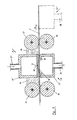
- FIG. 1 shows a top view schematically of part 1 of a galvanic system with a plurality of cleaning or treatment sections 2, 3, which are arranged in the direction of arrow 4 in the desired number one behind the other.
- the goods to be cleaned or treated here plates 5, in particular printed circuit boards for electronic purposes, is transported in the direction of arrow 6.
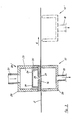
- FIG. 2 shows the above-mentioned route 2, the good 5 being seen from the narrow side edge. It has holes 7, which are drawn only in the area of the route for the sake of simplifying the drawing.
- the goods can be transported by transport rollers, not shown in the drawing.
- the liquid supply to the material 5 takes place by means of a surge section 8 with a housing 8 ', to which the liquid is fed via lines 9.
- the length L of the surge section can be seen in FIG. 1. It extends over the entire width of part 1, so that the material 5 can be cleaned or treated over its entire width B.
- the liquid passes through a slot 11, which also extends over the length L, into the surge chamber 12.
- a squeeze roller 13 located at the entrance and at the exit of the surge path allows a fluid accumulation 14 to be reached on both sides of the side walls of the housing 8 '. As already mentioned, this extends the distance over which the treatment liquid can act on the material.
- the surge of current arrives in the housing 17 of the suction section 10 in order to be suctioned off there through the line 18.
- the ratio of the amount of liquid supplied via the surge section 8 to the amount of liquid discharged via the suction section 10 can be adjusted in order to achieve the best effect in each case. In particular, it can be advantageous to draw off more liquid than to supply it per unit of time. In this case, the liquid jet through the bores 16 does not strike a liquid directly and the negative pressure prevailing in the suction path 10 supports the penetration of the bores 16 through the liquid.
- the rollers 13, 19 can also have a transport function. If necessary, separate transport rollers, not shown in the drawing, could also be provided, which are preferably not continuous like the squeeze rollers and counter-pressure rollers, but consist of individual disk-shaped roller pieces.
- the suction section 10 is directly opposite the surge section 8.
- it could also be provided offset in the direction of transport of the goods (as shown in dashed lines 10 ').
- offset which of the variants described above are used in practice depends on the type of material and in particular the holes to be treated or cleaned and also on whether it is a treatment station or a cleaning station.
- Fig. 3 shows in principle the same arrangement as Fig. 2, namely a surge section 20 provided above the goods 5, a directly opposite suction section 10 and / or a suction station 10 'offset in the transport direction 6 and also located below the goods 5.
- the liquid for example pure water
- the liquid is fed via a series of feeds 21 of larger diameter in the housing 22 of the surge path 20 to an antechamber 23, which is extends practically over the entire length L of the housing 22 of the surge path. From there, the liquid passes through two or more rows of bores 24 of smaller diameter (based on the diameter of the feeds 21) into a distributor space 25.
- the bores 24 are also provided one behind the other over the length L.
- the number of holes 24 of smaller diameter acts like a shadow mask.
- the liquid At the transition of the liquid from the antechamber 23 into the distribution space 25, there is a certain pressure drop of the liquid and at the same time a uniform distribution of the liquid within the distribution space 25 over the entire length L via the shadow mask L extending surge opening 26 the liquid in a steady surge and distributes itself into the surge chamber 27 in order to get from there through the bores 16 of the material and then downward into the housing 28 of the suction path 10 according to the arrows 18. From there, the suction takes place via the line 18.
- the suction section 10 and / or the use of the suction section 10 ' reference is made to the above statements.
- Squeeze rollers can also be provided to create a liquid jam or bed according to number 14.
- the bores 24 are offset from the feeds 21 in the transport direction 6, so that the liquid should not hit the slot-shaped opening 26 in a straight line from the feedings 21 through a bore 24. A corresponding offset of the bores 24 to the slot-shaped opening 26 is therefore also provided.
- surge section and the suction section can also be reversed, ie the surge section or the surge sections are located below the gutter and the suction section or suction sections above the gutter. This is not shown again separately in the drawings with regard to the exemplary embodiments according to FIGS. 2 and 3.
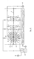
- two groups each, consisting of a surge section 8 and a suction section 10 are provided next to one another, with the surge section 8 below and in one group (this is the group treated first in the transport direction) the suction section 10 is located above the gutter, while the adjoining further group is arranged such that the surge section 8 is above and the suction section 10 is below the material.
- the goods to be treated i.e. whose holes are washed through one after the other from bottom to top and then again from top to bottom and thus exposed to intensive cleaning or treatment.
- squeeze rollers 13 and corresponding counter-rollers 13 ' can be provided, as is shown in the first group pair for the sake of simplifying the drawing.
- Transport rollers can also be provided, but are not shown for the sake of simplifying the drawing; or the transport function can also be performed here by the rollers 13, 13 '. This is the preferred embodiment of the invention.
- Fig. 4 shows in the left section, in which the squeeze rollers 13 are shown, that in addition to the gushing flows according to the vertical arrows 28 and also from the corresponding vertical flows branched approximately horizontal flows according to the arrow 29 can be achieved.
- the middle partition 30 between the two groups does not have to be led down to the material 5, but there must be a space for the flows 29 there.
- These flows 29 flush out blind bores or pocket extinguishers which cannot be cleaned or can only be cleaned very imperfectly from perpendicular flows. It depends on the dimensions of the flow cross sections whether the vertical or the horizontal flows are made the strongest.
- the middle pair of assemblies and the pair of assemblies on the right in FIG. 4 shows the above-mentioned embodiment, in which a gush flow flows from bottom to top in one group and a gush flow flows from top to bottom in the adjacent associated group, with cross currents not available.
- squeeze rollers e.g. 2, but this is not shown for the sake of simplifying the drawing.
- the circuit diagram shows a pressure pump 29 for the supply of the liquid to the surge sections 8 and a suction device or pump 30 for the suction of the liquid from the suction sections.
- a cleaning or treatment liquid can also be an acid, such as sulfuric acid, or a base.
- an acid such as sulfuric acid
- a base When cleaning, residues are also flushed out of holes 7 of very small diameter, for example 0.1 mm, perfectly.
- FIG. 3 is the preferred embodiment of the invention, which can also be provided in the embodiments according to FIG. 4.
- the principle of the invention explained at the outset can, however, also be implemented without this arrangement of anteroom and distribution space, in that the treatment or cleaning liquid is fed directly to the surge path according to FIG. 2. This variant also applies to the designs according to FIG. 4.
Applications Claiming Priority (1)
| Application Number | Priority Date | Filing Date | Title |
|---|---|---|---|
| DE3916694A DE3916694A1 (de) | 1989-05-23 | 1989-05-23 | Anordnung zur chemischen behandlung und/oder reinigung von gut, insbesondere von mit bohrungen versehenen leiterplatten, sowie dazugehoeriges verfahren |
Publications (1)
| Publication Number | Publication Date |
|---|---|
| EP0456870A1 true EP0456870A1 (fr) | 1991-11-21 |
Family
ID=6381191
Family Applications (1)
| Application Number | Title | Priority Date | Filing Date |
|---|---|---|---|
| EP90109413A Withdrawn EP0456870A1 (fr) | 1989-05-23 | 1990-05-18 | Dispositif pour le traitement et/ou le nettoyage chimique des matériels, notamment des plaques à circuits imprimés aux trous ainsi que procédé de ce traitement |
Country Status (5)
| Country | Link |
|---|---|
| EP (1) | EP0456870A1 (fr) |
| JP (1) | JPH03101880A (fr) |
| KR (1) | KR900018416A (fr) |
| CA (1) | CA2017286A1 (fr) |
| DE (1) | DE3916694A1 (fr) |
Cited By (2)
| Publication number | Priority date | Publication date | Assignee | Title |
|---|---|---|---|---|
| CN113634547A (zh) * | 2021-08-26 | 2021-11-12 | 南京屹正网络科技有限公司 | 电路板清洁设备及清洁方法 |
| CN115066096A (zh) * | 2022-05-23 | 2022-09-16 | 广德通灵电子有限公司 | 一种多层电路板制作工艺 |
Families Citing this family (10)
| Publication number | Priority date | Publication date | Assignee | Title |
|---|---|---|---|---|
| DE4040119A1 (de) * | 1990-12-13 | 1992-06-17 | Schering Ag | Verfahren zum durchfluten von bohrungen in plattenfoermigen werkstuecken, insbesondere leiterplatten, und vorrichtung hierfuer |
| DE4324330C2 (de) * | 1992-08-01 | 1994-11-17 | Atotech Deutschland Gmbh | Verfahren zum elektrolytischen Behandeln von insbesondere flachem Behandlungsgut, sowie Anordnung, insbesondere zur Durchführung dieses Verfahrens |
| JPH10512101A (ja) * | 1995-01-05 | 1998-11-17 | ヒューベル エゴン | 超微細孔を有したプレート形状の加工材料の処理のための方法と装置 |
| DE19530989C1 (de) * | 1995-08-23 | 1997-03-13 | Atotech Deutschland Gmbh | Verfahren zum Filmstrippen |
| KR100835015B1 (ko) * | 2006-12-28 | 2008-06-03 | 정상영 | 산업용 집진기의 케이스 |
| US7849554B2 (en) * | 2009-04-28 | 2010-12-14 | Lam Research Corporation | Apparatus and system for cleaning substrate |
| JP5419609B2 (ja) * | 2009-09-17 | 2014-02-19 | アジア化工機株式会社 | 洗浄装置及び洗浄方法 |
| CN104646358B (zh) * | 2013-11-21 | 2016-09-21 | 宜昌中威清洗机有限公司 | 一种发动机缸体机器人清洗机 |
| JP6337491B2 (ja) | 2014-02-12 | 2018-06-06 | 株式会社オートネットワーク技術研究所 | コネクタ |
| CN106076945B (zh) * | 2016-08-02 | 2018-10-26 | 宜昌英汉超声电气有限公司 | 混流清洗机 |
Citations (5)
| Publication number | Priority date | Publication date | Assignee | Title |
|---|---|---|---|---|
| EP0037483A1 (fr) * | 1980-03-21 | 1981-10-14 | Siemens Aktiengesellschaft | Procédé pour intensifier le rinçage et le nettoyage de perforations dans des pièces |
| DE3419141A1 (de) * | 1984-05-23 | 1985-11-28 | Gebr. Schmid GmbH & Co, 7290 Freudenstadt | Verfahren und vorrichtung zur behandlung plattenfoermiger gegenstaende, insbesondere von elektrischen leiterplatten mit einer mischung aus einer fluessigkeit und bimsmehl |
| GB2197581A (en) * | 1986-11-21 | 1988-05-25 | Teledyne Ind | Cleaning of printed circuit panels |
| EP0329807A1 (fr) * | 1988-02-25 | 1989-08-30 | Gebr. Schmid GmbH & Co. | Dispositif de traitement de cartes électriques à circuits imprimés |
| EP0212253B1 (fr) * | 1985-08-06 | 1990-02-28 | ATOTECH Deutschland GmbH | Procédé et dispositif de nettoyage, d'activation et/ou de métallisation de trous dans des plaquettes de circuit transportées horizontalement |
Family Cites Families (6)
| Publication number | Priority date | Publication date | Assignee | Title |
|---|---|---|---|---|
| DE2606984C3 (de) * | 1976-02-20 | 1978-08-24 | Siemens Ag | Verfahren und Einrichtung zum chemischen Reinigen von Kontaktierungslöchern in Leiterplatten |
| GB1537924A (en) * | 1976-03-04 | 1979-01-10 | Buckbee Mears Co | Apparatus for the distribution of fluid to the surface of an article |
| DE2925367C2 (de) * | 1979-06-22 | 1982-06-09 | Siemens AG, 1000 Berlin und 8000 München | Vorrichtung zur chemischen und galvanischen Metallabscheidung an einzelnen Bohrungswandungen von Leiterplatten |
| DE3022146A1 (de) * | 1980-06-13 | 1981-12-24 | Gebr. Schmid GmbH & Co, 7290 Freudenstadt | Vorrichtung zum absaugen plattenfoermiger gegenstaende |
| IT1137331B (it) * | 1981-04-10 | 1986-09-10 | Italtel Spa | Metodo per rendere conduttivi fori passanti in supporti per circuiti elettrici |
| DE3813518A1 (de) * | 1988-04-22 | 1989-11-02 | Hoellmueller Maschbau H | Maschine zum reinigen und/oder spuelen von bohrungen in leiterplatten |
-
1989
- 1989-05-23 DE DE3916694A patent/DE3916694A1/de not_active Ceased
-
1990
- 1990-05-18 EP EP90109413A patent/EP0456870A1/fr not_active Withdrawn
- 1990-05-21 KR KR1019900007245A patent/KR900018416A/ko not_active Application Discontinuation
- 1990-05-23 JP JP2131474A patent/JPH03101880A/ja active Pending
- 1990-05-23 CA CA002017286A patent/CA2017286A1/fr not_active Abandoned
Patent Citations (5)
| Publication number | Priority date | Publication date | Assignee | Title |
|---|---|---|---|---|
| EP0037483A1 (fr) * | 1980-03-21 | 1981-10-14 | Siemens Aktiengesellschaft | Procédé pour intensifier le rinçage et le nettoyage de perforations dans des pièces |
| DE3419141A1 (de) * | 1984-05-23 | 1985-11-28 | Gebr. Schmid GmbH & Co, 7290 Freudenstadt | Verfahren und vorrichtung zur behandlung plattenfoermiger gegenstaende, insbesondere von elektrischen leiterplatten mit einer mischung aus einer fluessigkeit und bimsmehl |
| EP0212253B1 (fr) * | 1985-08-06 | 1990-02-28 | ATOTECH Deutschland GmbH | Procédé et dispositif de nettoyage, d'activation et/ou de métallisation de trous dans des plaquettes de circuit transportées horizontalement |
| GB2197581A (en) * | 1986-11-21 | 1988-05-25 | Teledyne Ind | Cleaning of printed circuit panels |
| EP0329807A1 (fr) * | 1988-02-25 | 1989-08-30 | Gebr. Schmid GmbH & Co. | Dispositif de traitement de cartes électriques à circuits imprimés |
Cited By (2)
| Publication number | Priority date | Publication date | Assignee | Title |
|---|---|---|---|---|
| CN113634547A (zh) * | 2021-08-26 | 2021-11-12 | 南京屹正网络科技有限公司 | 电路板清洁设备及清洁方法 |
| CN115066096A (zh) * | 2022-05-23 | 2022-09-16 | 广德通灵电子有限公司 | 一种多层电路板制作工艺 |
Also Published As
| Publication number | Publication date |
|---|---|
| CA2017286A1 (fr) | 1990-11-23 |
| DE3916694A1 (de) | 1990-11-29 |
| JPH03101880A (ja) | 1991-04-26 |
| KR900018416A (ko) | 1990-12-21 |
Similar Documents
| Publication | Publication Date | Title |
|---|---|---|
| EP0427053B1 (fr) | Dispositif et procédé de revêtement des cartes de circuits imprimés | |
| DE2320199C3 (de) | Verfahren und Vorrichtung zum Reinigen gedruckter Leiterplatten | |
| DE69729578T2 (de) | Flüssigkeitsabgabevorrichtung und -verfahren | |
| DE2435924C2 (de) | Vorrichtung zum Reinigen von plattenförmigen Gegenständen | |
| DE2707536C3 (de) | Vorrichtung zum Aufbringen von Flüssigkeit auf sich bewegendes Material | |
| EP0456870A1 (fr) | Dispositif pour le traitement et/ou le nettoyage chimique des matériels, notamment des plaques à circuits imprimés aux trous ainsi que procédé de ce traitement | |
| DE3141250A1 (de) | Verfahren und vorrichtung zur fortlaufenden bearbeitung von gedruckten leiterplatten | |
| EP1704759B1 (fr) | Dispositif injecteur et procede de traitement d'un produit au moyen d'un milieu de traitement | |
| EP0399325B1 (fr) | Disposition pour le traitement et/ou le nettoyage de matériau, notamment des cartes de circuits imprimés pourvues de forures | |
| DE10039558B4 (de) | Vorrichtung zur Sprühbehandlung von Leiterplatten | |
| DE3235958C2 (fr) | ||
| EP1731231B1 (fr) | Machine de nettoyage de bouteilles | |
| DE19519211B4 (de) | Verfahren zur Behandlung von Gegenständen, insbesondere von Leiterplatten, sowie Vorrichtung zur Durchführung dieses Verfahrens | |
| DE3209726A1 (de) | Vorrichtung zum entwickeln von offsetdruckplatten | |
| DE3115317A1 (de) | "vorrichtung zum aufbringen von fluessigkeiten auf sich bewegendes material" | |
| EP1800524A2 (fr) | Procede et dispositif pour revetir des cartes de circuits imprimes | |
| DE4302564C2 (de) | Vorrichtung zum Ätzen, Beizen oder Entwickeln plattenförmiger Gegenstände, insbesondere von elektrischen Leiterplatten | |
| DE19633797B4 (de) | Vorrichtung zum Galvanisieren von elektronischen Leiterplatten oder dergleichen | |
| EP1230442B1 (fr) | Dispositif de traitement electrolytique de pieces sous forme de plaques, notamment des cartes de circuits | |
| EP0486711A1 (fr) | Dispositif pour l'enlèvement par soufflage d'un liquide se trouvant sur un objet | |
| EP0329807B2 (fr) | Dispositif de traitement de cartes électriques à circuits imprimés | |
| DE4223542A1 (de) | Vorrichtung zur Behandlung von Leiterplatten mit einer Behandlungsflüssigkeit | |
| DE19502272C2 (de) | Flaschenreinigungsmaschine in Einendbauweise | |
| DE19539606A1 (de) | Verfahren und Vorrichtung zum Behandeln plattenförmiger Gegenstände, insbesondere von elektronischen Leiterplatten oder dergleichen | |
| WO1988004700A1 (fr) | Procede et dispositif pour le revetement electrolytique au trempe de plaques, en particulier de plaquettes de circuits electriques imprimes |
Legal Events
| Date | Code | Title | Description |
|---|---|---|---|
| PUAI | Public reference made under article 153(3) epc to a published international application that has entered the european phase |
Free format text: ORIGINAL CODE: 0009012 |
|
| 17P | Request for examination filed |
Effective date: 19900518 |
|
| AK | Designated contracting states |
Kind code of ref document: A1 Designated state(s): BE CH DE DK ES FR GB IT LI LU NL SE |
|
| 17Q | First examination report despatched |
Effective date: 19940111 |
|
| STAA | Information on the status of an ep patent application or granted ep patent |
Free format text: STATUS: THE APPLICATION IS DEEMED TO BE WITHDRAWN |
|
| 18D | Application deemed to be withdrawn |
Effective date: 19940525 |