EP0452855B1 - Kopiergerät mit Dokumentenzufuhrgerät vom Umlauftyp - Google Patents
Kopiergerät mit Dokumentenzufuhrgerät vom Umlauftyp Download PDFInfo
- Publication number
- EP0452855B1 EP0452855B1 EP19910105977 EP91105977A EP0452855B1 EP 0452855 B1 EP0452855 B1 EP 0452855B1 EP 19910105977 EP19910105977 EP 19910105977 EP 91105977 A EP91105977 A EP 91105977A EP 0452855 B1 EP0452855 B1 EP 0452855B1
- Authority
- EP
- European Patent Office
- Prior art keywords
- document
- transporting
- copying
- documents
- path
- Prior art date
- Legal status (The legal status is an assumption and is not a legal conclusion. Google has not performed a legal analysis and makes no representation as to the accuracy of the status listed.)
- Expired - Lifetime
Links
Images


Classifications
-
- G—PHYSICS
- G03—PHOTOGRAPHY; CINEMATOGRAPHY; ANALOGOUS TECHNIQUES USING WAVES OTHER THAN OPTICAL WAVES; ELECTROGRAPHY; HOLOGRAPHY
- G03G—ELECTROGRAPHY; ELECTROPHOTOGRAPHY; MAGNETOGRAPHY
- G03G15/00—Apparatus for electrographic processes using a charge pattern
- G03G15/50—Machine control of apparatus for electrographic processes using a charge pattern, e.g. regulating differents parts of the machine, multimode copiers, microprocessor control
-
- G—PHYSICS
- G03—PHOTOGRAPHY; CINEMATOGRAPHY; ANALOGOUS TECHNIQUES USING WAVES OTHER THAN OPTICAL WAVES; ELECTROGRAPHY; HOLOGRAPHY
- G03G—ELECTROGRAPHY; ELECTROPHOTOGRAPHY; MAGNETOGRAPHY
- G03G15/00—Apparatus for electrographic processes using a charge pattern
- G03G15/60—Apparatus which relate to the handling of originals
-
- G—PHYSICS
- G03—PHOTOGRAPHY; CINEMATOGRAPHY; ANALOGOUS TECHNIQUES USING WAVES OTHER THAN OPTICAL WAVES; ELECTROGRAPHY; HOLOGRAPHY
- G03G—ELECTROGRAPHY; ELECTROPHOTOGRAPHY; MAGNETOGRAPHY
- G03G2215/00—Apparatus for electrophotographic processes
- G03G2215/00172—Apparatus for electrophotographic processes relative to the original handling
- G03G2215/00177—Apparatus for electrophotographic processes relative to the original handling for scanning
- G03G2215/00181—Apparatus for electrophotographic processes relative to the original handling for scanning concerning the original's state of motion
- G03G2215/00185—Apparatus for electrophotographic processes relative to the original handling for scanning concerning the original's state of motion original at rest
-
- G—PHYSICS
- G03—PHOTOGRAPHY; CINEMATOGRAPHY; ANALOGOUS TECHNIQUES USING WAVES OTHER THAN OPTICAL WAVES; ELECTROGRAPHY; HOLOGRAPHY
- G03G—ELECTROGRAPHY; ELECTROPHOTOGRAPHY; MAGNETOGRAPHY
- G03G2215/00—Apparatus for electrophotographic processes
- G03G2215/00172—Apparatus for electrophotographic processes relative to the original handling
- G03G2215/00177—Apparatus for electrophotographic processes relative to the original handling for scanning
- G03G2215/00181—Apparatus for electrophotographic processes relative to the original handling for scanning concerning the original's state of motion
- G03G2215/00189—Apparatus for electrophotographic processes relative to the original handling for scanning concerning the original's state of motion original moving
Definitions
- the present invention relates to a copying machine which comprises a recirculating document feeding apparatus for sequentially and circulatorily feeding and transporting a sheet document to a reading station where document images are to be read and effects copying operation in various copying modes in cooperation with the document feeding apparatus.
- document feeding apparatus for feeding a plurality of documents sequentially to a reading station below which exposure means for reading document images is disposed in order to copy effectively a plurality of document sheets of same size.
- a document feeding apparatus is referred to as a recirculating document feeding apparatus, in which the documents placed in a document placing member are fed therefrom, transported to the reading station, and then returned to the placing member again. In this way, the documents are fed circulatorily in the recirculating document feeding apparatus.
- Document JP-A-60-83930 discloses an original carrying controller designed to shorten the original eject time and the eject time of the first copy by carrying originals at an exposure speed during exposure of originals and carrying originals at a high speed during operations other than exposure.
- the carrying speed is switched to the exposure speed.
- the original After the original passes the exposure point sensor, the original is carried for a certain length by the counted value of an encoder provided on a carrying motor, and exposure is terminated.
- the carrying speed is switched from the exposure speed to a high speed again, and the original is carried to an original eject switching gate or is carried to the exposure point sensor for the second copy.
- the original eject time and the eject time of the first copy are shortened.
- both sides of the document are fed to the reading stations facing the corresponding reading stations.
- the document image read at the reading station is copied onto recording paper in the copying machine cooperating with the feeding apparatus.
- various copying modes can be effected, such as a mode in which the documents having images on both sides thereof (hereinafter referred to as a duplex document) are copied correspondingly onto one or both sides of the recording paper (hereinafter referred to as a duplex copy) or another mode in which the documents having an image on one side thereof (hereinafter referred to as a simplex document) are copied onto both sides of the recording paper.
- the recirculating document feeding apparatus feeds a plurality of documents one by one to the reading station.
- the document image exposingly read from one side of the document is formed into a latent image onto, for example, a photoreceptor rotating at a constant speed, and further developed into a toner image, which is copied onto one side of the fed recording paper.
- the recording paper to one side of which the copying operation has been effected is temporarily stored in an intermediate tray, then fed to the photoreceptor again.
- the document image read from the document fed to the reading station succeedingly to the document whose image has been copied onto one side of the recording paper is copied onto the other side of the recording paper. Subsequently, the recording paper is discharged. In this way, duplex copies can be obtained from a plurality of simplex documents.
- duplex copies are obtained from the simplex documents
- One is to copy the precollated simplex documents with respect to page number thereof from the last page document.
- the other is to copy the documents from the first page document.
- the copying operation requires to be changed depending on whether the number of the documents is odd or even. More specifically, in the case where the number of the documents is even, a completely collated duplex copy set can be obtained just by copying the document images of the simplex documents sequentially onto both sides of the recoding paper.
- the copy operator counts the number of the documents beforehand, and causes to switch to an appropriate copying process by inputting the information indicative of whether the number of the documents is odd or even through the use of a control panel.
- a plurality of documents placed in the placing member are circulated through the transporting path past the reading station without being copied, thereby effecting the counting operation for automatically counting the number of the documents by means of sensors or the like.
- the counting operation by transporting the documents without being copied within the recirculating document feeding apparatus does not involve a cumbersome operation, hence having been utilized in recent years.
- the counting operation can be effected in the cases which require counting of the number of the documents beforehand, such as a blank paper inserting mode.
- a blank paper inserting mode In the blank paper inserting mode, a blank recording paper is inserted every plural number of copied recording papers.
- the copying modes of the copying machine generally include a standard mode in which the document image of the document is copied onto the recording paper in the same size, a reduction mode in which the document image is copied onto the recording paper with reduced size thereof, and an enlargement mode in which the document image is copied onto the recording paper with enlarged size thereof.
- a standard mode in which the document image of the document is copied onto the recording paper in the same size
- a reduction mode in which the document image is copied onto the recording paper with reduced size thereof
- an enlargement mode in which the document image is copied onto the recording paper with enlarged size thereof.
- the transporting speed of the documents sequentially transported without being copied in the counting operation has been set at a constant transporting speed at which the documents are transported to the reading station to be copied. More specifically, despite the fact that the transporting speed at which the document is transported to the reading station can be variable in accordance with the respective copying magnification, the constant transporting speed of the document in the counting operation is set equal to the transporting speed to the reading station in the standard mode. Accordingly, since the documents are transported without being copied at the constant transporting speed in accordance with the standard mode despite the capability of transporting the document more rapidly, a large amount of time is uselessly spent on the counting operation. This results in spending much time to obtain the copied recording paper through the copying operation succeeding thereto.
- the present invention provides the copying machine provided with a recirculating document feeding apparatus in which the document sheets placed in a placing member are sequentially fed to the reading station, at which the document images to be copied are read, at a transporting speed determined in accordance with a selected copying magnification and returned to the placing member again after reading the document images thereof, and copies the read document image onto a recording paper which comprises controlling means for determining transporting speed of the document to be higher than the transporting speed determined in accordance with the minimum copying magnification when the documents are transported without being copied for the counting operation.
- the copying machine is provided with the recirculating document feeding apparatus for sequentially feeding the document sheets placed in the placing member to the reading station and therefrom returning the documents after reading the document images at the reading station to the placing member, i.e. feeding the documents circulatorily.
- the transporting speed of the documents fed to the reading station is set in accordance with a selected copying magnification.
- the document images read at the reading station are copied onto recording paper sequentially fed in the main body of the copying machine.
- the documents placed in the placing means are circulated through a transporting path without the document images being read at the reading station.
- the transporting speed of the documents in the counting operation is set by the controlling means so as to be higher than the transporting speed at which the documents are transported to the reading station in accordance with the minimum copying magnification in the reduction mode.
- control of the transporting speed can be rough compared to control of the transporting speed when the documents are to be copied, thereby enabling high speed transportation of the documents while eliminating the need for a new circuit for controlling the transporting speed.
- the transporting speed of the documents to be transported without being copied in the counting operation can be set at maximum transporting speed, thereby enabling the time required for the counting operation to be remarkably reduced.
- the transportation of the documents is effected at the maximum transporting speed higher than the transporting speed in accordance with the minimum copying magnification in the counting operation of the documents.
- the time required for the counting operation can be remarkably reduced.
- the counting operation is rapidly switched to the copying operation, reducing the time required for the entire copying operation and thereby operability of the copying machine will be improved.
- Fig. 1 is a schematic cross-sectional view showing a transfer-type electrostatic copying machine provided with a recirculating document feeding apparatus 1.
- a main body 100 of the copying machine In the center of interior construction of a main body 100 of the copying machine is disposed a right cylindrical photoreceptor 101 rotatable at a specific rate.
- respective copying processing portions In the periphery of the photoreceptor 101 are respective copying processing portions together with a corona discharger 102 for charging and a developing device 103.
- a fixing device 104 On the left side of Fig. 1 with respect to the photoreceptor 101 is disposed a fixing device 104.
- the recirculating document feeding apparatus 1 is arranged on top surface of the main body 100 of the copying machine.
- a first reading station 20 and a second reading station 21 disposed respectively right below a first support cylinder 5 and a second support cylinder 6 of the document feeding apparatus 1 are aligned in parallel substantially in the same plane on the top surface of the main body 100 of the copying machine.
- a third reading station 105 for a bound book or the like constituting exposure means 149 capable of performing a dual system reading exposure method.
- Fig. 2 is a schematic cross-sectional view of the recirculating document feeding apparatus 1.
- the recirculating document feeding apparatus 1 comprises a document placing member 2 used as means for placing the documents, a feed means 3 for feeding the sheets of the documents one by one from the document placing member 2, the first support cylinder 5 in the form of right cylinder for transporting the document along the outer surface thereof and having one side of the document faced to the first reading station 20, the second support cylinder 6 in the form of right cylinder for having the other side of the document being transported faced to the second reading station 21, document transporting means 7 for transporting the document from the document placing member 2 to the first support cylinder 5, a document inverting means 8 provided between the first support cylinder 5 and the second support cylinder 6 for inverting a transporting state of the document so that the document, one side of which is faced to the first reading station 20, has the other side thereof faced to the second reading station 21, and document returning means 9 for returning the document from the second support cylinder 6 to the document placing member 2.
- a plurality of document sheets precollated with respect to page number thereof are placed with one edge portions (left edge portion side in Fig. 1) thereof aligned by a document aligning member 10.
- the documents are placed on a document transporting belt 11 with document side having the smallest page number placed face-down.
- a feed roller 12 constituting the feed means 3 for feeding sequentially the documents D from the uppermost document out of the document placing member 2.
- the feed roller 12 is drivingly rotated at a predetermined timing by a document feed motor M2 in the direction of an arrow, and pressed against the document DO stacked uppermost through a lever 13 by energization of a solenoid or the like when being rotated, thereby feeding the document DO from the documents D to the document transporting means 7.
- the document transporting means 7, to which the documents D is fed one by one from the document placing member 2 by the feed roller 12, comprises a transporting path 14 curved from the horizontal direction down to the vertical direction as shown in Fig. 2.
- a pair of separating rollers 15a and 15b for preventing multiple feeding of the documents.
- the separating roller 15a disposed above is drivingly rotated in the direction of transport of the document, and the separating roller 15b disposed below is drivingly rotated in the opposite direction of transport of the document.
- the documents D are reliably separately fed to the transporting path 14 one by one by passing the nip between the separating roller 15a and 15b.
- pairs of rollers 16a, 16b, 16c, and 16d which are spaced with respect to each other.
- pairs of transporting rollers 16a to 16d rotatably come into contact with both sides of the document D respectively.
- the pairs of transporting rollers 16a to 16d are forcefully rotated by the document feed motor M3 to guidingly feed the document D in the direction of an arrow 17.
- a document feed sensor S2 Alongside of the inlet of the transporting path 14 is disposed a document feed sensor S2, and alongside of the outlet of the transporting path 14 is disposed a sensor S3 before the first reading station in the direction of transport of the document.
- first resist rollers 19a and 19b are coupled to a drive shaft through a clutch CLT1, not shown, and stopped rotating and rotated again by ON-OFF control of the clutch CLT1.
- the ON-OFF control of the clutch CLT1 is controlled in accordance with the operator's desired copying mode.
- the rotation of resist rollers 19a and 19b is stopped to have the document D wait therebetween so as to synchronize with the transport of recording paper in the main body 100 of the copying machine. After synchronization with the transport of recording paper, the resist roller 19a and 19b are rotated.again to transport the document D to the first support cylinder 5.
- the resist rollers 19a and 19b are normally rotated merely as rollers for transporting the documents similar to the other transporting rollers to pass the document D without stopping it therebetween.
- the transporting rollers 16c and 16d which are disposed upstream of the direction of transport of the document with respect to the resist rollers 19a and 19b by a length not longer than the allowable maximum length L1 of the document D being transported, are not stopped rotating until the transport of the document D is completed.
- the first resist rollers 19a and 19b are operated as resist rollers for adjusting the timing for the document D to be fed to the first support cylinder 5 by having the document D wait therebetween, rotation of the transporting rollers 16c and 16d is controlled as well.
- Reading stations for reading an image of the document D include the first reading station 20 and the second reading station 21 corresponding to respective bottom end surfaces of the first support cylinder 5 and the second support cylinder 6 arranged in parallel and spaced from each other in the horizontal direction.
- the first reading station 20 and the second reading station 21 are positioned in the same flat surface as shown in the figure.
- the support cylinders 5, 6 are drivingly rotated respectively by document transporting motors M4, M5 in the clockwise direction (see Fig. 2) synchronized with transporting speed at which the document is to be fed to each of reading stations 20 and 21 in accordance with a copying speed at which the document image is copied onto the recording paper, or a set copying magnification.
- the support cylinders 5, 6 have driven rollers 22a to 22d, 23a to 23d respectively provided along the outer surface thereof and spaced at specific intervals.
- the document D is rolled pressingly against the outer surfaces of the support cylinders 5 and 6 by these driven rollers, and fed along the circumferential transporting paths 20a and 20b defined on the outer side of the support cylinders 5 and 6.
- the inverting path 30 has a first path 30a and a second path 30b extending upwardly with inclination from the portions of the circumferential transporting paths 20a and 21a opposing each other, and a third path 30c extending in the horizontal direction from the junction of the first and the second paths 30a and 30b.
- a direction switching claw 31 is provided at the inlet portion of the first path 30a continuously connected to the circumferential transporting path 20a of the first support cylinder 5.
- the direction switching claw 31 is actuated by a solenoid SOL1 to selectively transport the document D to either of the first path 30a or the circumferential transporting path 20a of the first support cylinder. More specifically, the document D passed through the first reading station 20 is transported to the first path 30a by actuating the direction switching claw 31 to move to a position shown by a solid line in Fig. 1 in the case where it is sufficient for the document D to be read and exposed only once in accordance with the operator's desired copying mode.
- the direction switching claw 31 is actuated to move to a position shown by a two-dot line to transport the document D along the circumferential path 20a of the first support cylinder 5 more than once.
- the direction switching claw 31 is actuated to move to the solid lined position to transport the document D to the first path 30a.
- a sensor S4 positioned after the first reading station for detecting a trailing edge of the document D, a pair of rollers 34a and 34b, and a direction switching claw 35 in the order thereof from the upstream of the transporting direction of the document D.
- a sensor signal from the sensor S4 is controlled inversion operation for inverting both sides of the document D to be described hereinafter.
- the document D is transported to the third path 30c through the direction switching claw 35 by the drivingly rotated rollers 34a and 34b.
- Two pairs of rollers 36a, 36b and 37a, 37b are disposed along the third path 30c while holding the third path 30c therebetween.
- the rollers 36a and 37a are rotated in normal and reverse directions by a motor M6 for inverting the document.
- the transporting rollers 36 and 37 transport the document D in the direction of an arrow 40b by invertingly rotating the motor M6 at the time when the trailing edge of the document D passed through the direction switching claw 35.
- the direction switching claw 35 is actuated to move to a solid lined position shown in Fig. 1 by a solenoid SOL2 disconnecting the first path 30a to the third path 30c while connecting the second path 30b thereto, thereby rendering the document D transported to the second path 30b.
- the second path 30b has the roller 34c provided therealong, and is in pressing contact with the roller 34a by a solenoid SOL3 and thereby transports the document D while holding it therebetween.
- the rollers 36 and 37 rotatable in normal and reverse directions are adapted to embody the inverting operation for inverting both sides of the document as hereinbelow described, a belt transporting device and an air transporting device, for example, may also be adapted for the same purpose.
- rotational forces of the rollers 34a and 34c are adapted to assist the second support cylinder 6 in transporting the document D to the second reading station 21 whereby the document D is rolled to the outer surface thereof.
- a sensor S5 positioned before the second reading station for detecting passage of the trailing edge of the document D.
- a pair of second resist rollers 59a and 59b coupled to the drive shaft through a clutch CLT2, although unillustrated.
- the rotation of the second resist rollers is stopped and started again by the ON-OFF control by the clutch CLT2.
- the ON-OFF control by the clutch CLT2 is controlled in accordance with the operator's desired copying mode.
- the resist rollers 59a and 59b are stopped rotating to have the document D wait so as to synchronize with the recording paper. After the document D is synchronized with the recording paper, the rollers 59a and 59b are started rotating again so as to transport the document D to the second support cylinder 6. On the other hand, in the case where the document D is not required to be read, the rollers 59a and 59b are rotated as transporting rollers at all times to pass the document D therebetween without having the document D wait.
- operation by the solenoid SOL3 is controlled in accordance with rotation of the rollers 59a and 59b.
- transporting rollers 36 and 37 are arranged on the downstream side in the transporting direction with respect to the second resist rollers 59a and 59b by the length not longer than an allowable maximum length L1 of the document D to be transported.
- the second resist rollers 59a and 59b are to the transporting rollers 36 and 37 what the first resist rollers 19a and 19b are to the transporting rollers 16c and 16d in operational relationship thereof.
- the transporting rollers 36 and 37 for transporting the document D to the second support cylinder 6 are kept rotating until the transport of the document D is completed.
- the rotation of the transporting rollers 36 and 37 is temporarily stopped when the leading edge of the document D reaches the nip between the rollers 59a and 59b. Thereafter, at the same time when the second resist rollers 59a and 59b are started rotating, the transporting rollers 36 and 37 are also started rotating, thereby resuming transport of the document D.
- one side of the document D which has already been faced to the first reading station 20 is faced and rolled to the outer surface of the second support cylinder 6 by the transporting direction of the document D being reversed in the inverting path 30. Accordingly, the document D is transported to the second support cylinder 6 with the other side thereof, which has not yet faced the reading station, face down. In view of this, the other side of the document D transported at a transporting speed in accordance with the selected copying magnification is exposed in the second reading station 21 and consequently an original image thereof is read.
- the direction switching claw 46 is arranged in a location where the document passed through the second reading station 21 is branched off to a transporting path 45 of the document returning means 9 from the circumferential transporting path 21a of the second support cylinder 6.
- the direction switching claw 46 is actuated by a solenoid SOL4 to selectively open or close the circumferential transporting path 21a to the transporting path 45.
- the circumferential transporting path 21a is open to the transporting path 45, to which the document D is thereby transported.
- the transporting path 45 is closed. Accordingly, after having been transported in the circumferential transporting path 21a the required number of times, the document D is transported to the transporting path 45.
- the document images on both sides of the document D can be read, by exposing and reading the document images on one side and the other side of the document D in the first reading station 20 and the second reading station 21 respectively. Also, since the document D is exposingly read in the first and the second reading station 20, 21 respectively the required number of times, a plurality of sets of copies can be made from a plurality of the documents D.
- the transporting path 45 is connected to the end portion of a transport belt 11 on the below side for transporting the document D thereto. More specifically, the transporting path 45 has pairs of transporting rollers 50 and 51 provided therefor for transporting the document D. Moreover, in the vicinity of the outlet of the transporting path 45 is disposed a sensor S6 positioned before the document placing member 2 for detecting passage of the document D. Operation of the transport belt 11 and the document returning means 9 is controlled in accordance with a sensor signal from the sensor S6.
- the endless transport belt 11 is installed encirclingly on rollers 55a, 55b, 55c, and 55d spaced laterally and longitudinally to one another as shown in the figure.
- the driving roller 55b is drivingly rotated in the direction of an arrow by a motor M7 adapted to return the document D to the placing member 2 in accordance with the sensor signal from the sensor S6, thereby drivingly rotating the transport belt 11 in a counterclockwise direction (see Fig. 2.)
- the upper stretching portion of the transport belt 11 also serves as a placing member for the documents D.
- a document sucking roller 56 is disposed in a position adjacent to the transporting path 45 and feeds the document D to the nip between the upper stretching portion of the transport belt 11 and the bottommost stacked document D by transporting force with the transport belt 11.
- a document kick-up roller 58 is provided below the end portion on the downstream side in the feeding direction of the documents D placed in the document placing member 2.
- the kick-up roller 58 lifts temporarily the right edge portion of the stacked documents D from the transport belt 11, expanding reliably an opening for feeding the document into the bottommost position.
- the document D fed into the bottommost position is completely returned to the document placing member 2 by the motor M7 for driving the transport belt 11 being stopped driving at the time when the leading end thereof reaches the edge aligning member 10.
- the document placing member 2 is provided with an actuating member 60 comprising, for example, a specularly formed stainless plate for detecting one circulation of the documents D placed therein.
- the actuating member 60 is in a position shown by a solid line in Fig. 1 before the operator places a stack of documents D in the document placing member 2, and then the documents D are placed thereon.
- the actuating member 60 gradually shifts upwardly.
- the actuating member 60 is interposed between the unfed documents and the restacked documents, separating the both from each other. When all the documents D are circulated, the actuating member 60 reaches the uppermost position shown by a two-dot line.
- the actuating member 60 which has reached the uppermost position has an exposed state thereof detected by, for example, the sensor S1 included in the document placing member 2 detecting one circulation of the document, the sensor S1 being comprised of a combination of a light emitting element and a photoreceiving element.
- the sensor S1 Upon detection of the exposed state of the actuating member 60, the sensor S1 generates a sensor signal indicative of completion of one circulation of the document.
- Such an operation as to make sets of copies by the operator's desired number on the main body 100 side of the copying machine is controlled in accordance with the sensor signal from the sensor S1.
- the actuating member 60 is drivingly rotated by 180 degrees by a motor M1 for driving the actuating member 60 and returned to the bottom-most position (original position) with the document D placed thereon.
- a light source 150 for slit exposing a side of the document in the upper portion of the interior of the main body 100 of the copying machine are disposed a light source 150 for slit exposing a side of the document, reflectors 151a, 151b, 151c, and 151d, and the exposure means 149 including a zoom lens 152.
- the exposure means 149 when the light from the light source 150 is incident upon the side of the document D, the reflected light representative of a document image forms an image in exposure region 130 of the photoreceptor 101 through the reflectors 151a to 151d and the lens 152.
- the exposure means 149 performs reading and exposure in a pausing state in the first and the second reading stations 20, 21 right below the first and the second support cylinders 5, 6 respectively in accordance with transport of the document D at a transporting speed based on the copying magnification in the document feeding apparatus 1. Moreover, in the case where a book or the like is placed on the third reading station 105, a first moving body comprising the light source 150 and the reflector 151a performs exposure and reading while scanning the third reading station 105. These two reading exposure methods are effected by driving the exposure means 149 by a motor M13.
- the photoreceptor 101 As drivingly rotated in the clockwise direction at a constant speed, the photoreceptor 101 is electrostatically charged by the corona discharger 102. In the exposure region 130 of the charged photoreceptor 101, the reflected light through the exposure means 149 forms an electrostatic latent image corresponding to the read document image. The electrostatic latent image thus formed is developed into an toner image by the developing device 103. The toner image is transferred to a recording paper P in transfer region 129 by a corona discharger 131 for transfer, the recording paper P being fed to the photoreceptor 101 to be described hereinafter. After the transfer to the recording paper P, the image is transported to a fixing device 104 by a transporting mechanism 132 and thereby fixed.
- the residual toner on the photoreceptor 101 is removed by a cleaning device 133 provided downstream of the transfer region 129 in the rotating direction of the photoreceptor 101. Thereafter, the residual charge on the photoreceptor 101 is removed by a charge removing device 134, and the surface of the photoreceptor 101 is charged by the corona discharger 102 so as to be ready for formation of a succeeding image.
- Paper cassettes 106a and 106b containing a stack of the recording paper P are loaded on one side of the main body 100 of the copying machine, and paper cassettes 106c and 106d are loaded in the bottom portion thereof.
- the stack of the recording paper P placed in the paper cassettes 106a to 106d are fed from the uppermost stacked recording paper one by one to feeding paths 108a to 108d.
- the recording paper P is fed as paper feed rollers 109a to 109d disposed on upper surface of each of paper cassettes 106a to 106d are drivingly rotated by motors M8.
- the feeding paths 108a to 108d and a feeding path 115 from an intermediate tray 113 has respectively transporting rollers 107a to 107e, which are drivingly rotated by a motor M9 to feed the recording paper P to the copying operation processing portion.
- Transporting timing of the recording paper P fed from the paper cassettes 106a to 106d and the intermediate tray 113 is controlled by third resist rollers 160a, 160b disposed on the transporting path to the photoreceptor 101. More specifically, when a leading edge of the recording paper P transported to the photoreceptor 101 is fed to the nip between the third resist rollers 160a and 160b, transport of the recording paper P is temporarily stopped.
- the first resist rollers 19a, 19b are employed for controlling the transport of the document D and the second resist rollers 59a, 59b are employed merely for transporting the document D, both the first and the second resist rollers being provided in the document feeding apparatus 1.
- the first resist rollers 19a, 19b are drivingly rotated to restart transporting the document D and, after a preset period of time, the third resist rollers 160a, 160b are drivingly rotated to restart transporting the recording paper P.
- the preset period of time is the time required for the second operation subtracted from that required for the first operation.
- the first operation means that the document D transported again by the first resist rollers 19a, 19b after the temporary stop therebetween are exposed and read in the first reading station 20, and the downstream side edge of the toner image in the moving direction, corresponding to the original image, formed on the photoreceptor 101 reaches the transfer region 129.
- the second operation means that the leading edge of the recording paper P transported by the third resist rollers 160a, 160b after the temporary stop therebetween reaches the transfer region 129.
- the preset period of time is counted down by a timer provided in, for example, a controlling device. Accordingly, the transferred image and the recording paper P can be reliably registered by synchronizing with each other.
- the first resist rollers 19a, 19b are employed merely for transporting the document D and the second rollers 59a, 59b are employed for resisting.
- the relationship between the timing of transport of the document D by the second resist rollers 59a, 59b and the timing of transport of the record paper P by the third resist rollers 160a, 160b is similar to the relationship in synchronizing the timings of the first resist rollers 19a, 19b and the third resist rollers 160a, 160b.
- a discharge tray 110 On the other side of the main body 100 of the copying machine is provided a discharge tray 110, to which a solenoid SOL 8 is mounted.
- the solenoid SOL 8 When the solenoid SOL 8 is magnetized for a predetermined period of time, the discharge tray 110 is shifted forwardly in the direction normal to the surface of Fig. 1.
- the solenoid SOL 8 is demagnetized for a predetermined period of time, the discharge tray 110 is shifted rearwardly in the direction normal to the surface of Fig. 1. Thereby, plural sets of recording paper having plural document images copied thereon can be discharged to the discharge tray 110 in sorted state.
- a discharging path 111 for discharging the recording paper P passed through the fixing device 104 by way of the copying operation processing portion and an inverting path 112 for inverting the recording paper P, the inverting path 112 being diverged from the discharging path 111.
- the recording paper P passed through the copying operation processing portion and the fixing device 104 and having on one side thereof formed the image corresponding to the original image thereon is discharged to the discharge tray 110 in any one of the following three modes (i) to (iii) in accordance with the operator's desired copying mode.
- the inverting path 112 comprises paths 112a and 112b diverged from two locations in the discharging path 111, a path 112c into which the paths 112a and 112b are joined, and a path 112d diverged from the path 112c and directed toward the intermediate tray 113.
- a first direction switching claw 115 is disposed in the location from which the path 112a is diverged from the discharging path 111.
- a second direction switching claw 116 is disposed in a location where the paths 112a and 112b are joined.
- a third direction switching claw 117 is disposed in a location where the paths 112d are diverged from the path 112c.
- pairs of rollers 118a, 118b, and 118c In the vicinity of the joining location of the paths 112a and 112b are provided pairs of rollers 118a, 118b, and 118c. In the vicinity of the diverging location of the paths 112c and 112d are provided pairs of rollers 119a, 119b, and 119c. Each of these pairs of rollers are employed for transporting the recording paper P. Further, in the path 112c are disposed a pair of rollers 120 for inverting the recording paper P in the vicinity of the joining location of the paths 112a and 112b, the pair of rollers 120 being rotated in normal and reverse directions by an unillustrated motor M11 so as to reverse the transporting direction of the recording paper P.
- a pair of rollers 121 for inverting the recording paper P which are rotated in normal and reverse directions by an unillustrated motor M12.
- a sensor S13 for detecting discharge of the recording paper P is disposed in the vicinity of the outlet of the discharging path 111.
- Sensors S14, S15 for detecting inversion of the recording paper P are disposed in the vicinity of the diverging location of the discharging path 111 and the path 112a and in path 112c respectively.
- a sensor S16 for detecting an inlet of the intermediate tray 113 is disposed in the vicinity of the outlet of the path 112d.
- the direction switching claw 115 is actuated to close the path 112a to the discharging path 111 so that the recording paper P is discharged along the discharging path 111.
- the direction switching claw 115 is actuated to close the discharging path 111 so that the recording paper P is transported through the path 112a, and the direction switching claw 116 is actuated to open the path 112c, in which the recording paper P has the transporting direction thereof reversed by the inverting rollers 121.
- the direction switching claw 117 is actuated to close the path 112c so as to open the path 112d for the recording paper P, which is in turn introduced to the intermediate tray 113.
- the recording paper P has the transporting direction thereof reversed by the inverting rollers 120.
- the direction switching claw 116 is actuated to close the path 112a so as to open the path 112b for the recording paper P, which is in turn introduced to the discharging path 111 through the path 112b.
- a sensor S10 is adapted to detect that the recording paper P is fed from the paper cassette.
- a sensor S11 is adapted to detect that the recording paper P is in a position just before the transfer region 129.
- a sensor S12 is adapted to detect that the recording paper P has just had the transferred image fixed thereon.
- a sensor S17 is adapted to detect presence or absence of the paper in the intermediate tray 113.
- a sensor S18 is adapted to detect that the paper has been fed from the intermediate tray 113.
- a copying machine provided with such a recirculating document feeding apparatus 1 as described above is capable of effecting the following copying operations by recirculating a plurality of document sheets D plural times in accordance with the operator's desired copying mode.
- the document D is exposed and read plural times while being circulated around the support cylinder while being rolled thereto so as to make a plurality of copies during one circulation of the document D in accordance with the operator's desired copying mode.
- the rotating speeds of the resist rollers 19a, 19b and 59a, 59b disposed before and after the support cylinders 5 and 6 in the transporting direction and the other transporting rollers are controlled in accordance with the set copying magnification.
- a magnification for the document image read onto the photoreceptor 101 drivingly rotated at the constant speed is regulated so that the document image can be copied onto the recording paper in a desired size corresponding to a standard mode, reduction mode, and enlargement mode. More specifically, a speed at which the document D is transported to each of the reading stations 20, 21 in the standard mode is made a reference speed.
- the support cylinders 5, 6 and the resist rollers or the like are controlled so as to increase rotating speeds thereof based on the reduction magnification and thereby the document D is transported to each of the reading stations 20, 21 at a higher speed.
- the support cylinders 5, 6 and the resist rollers or the like are controlled so as to decrease rotating speeds thereof based on the enlargement magnification and thereby the document D is transported to each of the reading stations 20, 21 at a lower speed.
- the controlling operation defers depending on whether the number of the documents D is odd or even. Accordingly, before the copying operation is effected in the set copying mode, a counting operation for the documents D is effected so mode, a counting operation for the documents D is effected so as to determine whether the number of the documents D is odd or even. In this embodiment, the counting operation is effected automatically by the recirculating document feeding apparatus 1.
- the documents D to be copied stacked in the document placing member 2 are sequentially fed through the transporting path to the support cylinder 5, the document inverting means 8, and the support cylinder 6 while the resist rollers 19a, 19b, and 59a, 59b are employed merely for transporting the documents D.
- the documents are returned to the placing member 2 by means of the transporting belt 11.
- the documents D can be counted by any one of the optical sensors S2 to S6 disposed in the vicinity of the transporting course.
- the sensor S1 detects that all the documents D have circulated the transporting course thereof.
- the documents D transported to the reading stations 20, 21 by way of the support cylinders 5, 6 are not to be exposed and read by the exposure means 149. That is to say, the documents D are merely to be transported without the copying operation. In such a mere transportation of the documents D, a fastest possible operation is desired irrespective of set copying magnification.
- the maximum transporting speed of the document D in the transporting course thereof is higher than the speed at which the copying operation at the minimum copying magnification is effected in the reduction mode. Accordingly, the support cylinders 5, 6 and the resist rollers or the like are controllably rotated based on the maximum transporting speed in the counting operation.
- the documents D are transported without being copied in the counting operation at a high speed, hence the time required to effect the counting operation can be remarkably reduced. As a result, the time required to obtain the duplex copies from the simplex documents D (simplex -> duplex mode) after being placed in the placing member 2 can be remarkably reduced.
- such a counting operation as described above can be preferably embodied to count the number of the documents beforehand in a mode wherein a sheet of blank recording paper is inserted to between two desired sheets of a plurality of copied ones, or a blank paper inserting mode, other than a (simplex -> duplex) mode. More specifically, in the blank paper inserting mode, the necessary information, for example, the information indicative of between the n page and n+1 page, is inputted through the use of a keyed control panel and thereby the blank sheet of recording paper is discharged without being copied in the copying operation processing portion every desired number of the recording paper to be laid between the copied papers.
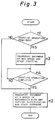
- Fig. 3 is a flow chart describing the counting operation of the invention.
- a program shown in Fig. 3 is executed when various copying modes are selected through the use of the control panel provided on the main body 100 of the copying machine.
- Step n1 it is determined whether a document counting mode is selected in response to the copying mode inputted through the use of the control panel. If the document counting mode is not selected, i.e. the (duplex ->duplex) mode, (simplex -> simplex) mode, or the like is selected, this routine proceeds to Step n2 in which the copying operation is effected by transporting the document D at a transporting speed in accordance with the selected copying magnification to the reading stations 20, 21 to be exposed and read.
- Step n1 i.e. the (simplex-duplex) mode, blank paper inserting mode, or the like is selected
- the document counting mode is effected.
- this routine proceeds to Step n3 in which the counting operation is started by transporting the documents D at maximum transporting speed higher than the transporting speed in accordance with the minimum copying magnification in the reduction mode.
- Step n4 it is determined whether all the documents D placed in the placing member 2 have been circulated through the transporting course thereof. In other words, it is determined whether the counting operation has been completed. Consequently, this routine proceeds to Step n2 in which the copying operation is effected by transporting the documents D to the reading stations 20, 21 to be exposed and read.
- Fig. 4 is a block diagram showing an electric construction of a controlling device for controlling the main body 100 of the copying machine and the document feeding apparatus 1.
- Motors M1, M2, M3, ...for driving the transporting rollers and the support cylinders and the like are connected to a motor driving circuit 170.
- Clutches CLT1, CLT2, CLT3,... for synchronizing transport of the document D in the feeding apparatus 1 and transport of the recording paper P in the main body 100 of the copying machine with each other are connected to a clutch driving circuit 171.
- Solenoids SOL1, SOL2, ...for actuating the direction switching claws 31, 35, ... in the transporting paths are connected to a solenoid driving circuit 172.
- driving circuits 170 to 172 are connected to a interface circuit 178 along with a DC power source 173, sensors S1, S2, S3,...for detecting transporting state of the document D and the recording paper P, an optical system driving circuit 174, input control keys 176 on the control panel 175 disposed on the main body 100 of the copying machine, and a display driving circuit 177 for driving a display device on the control panel 175.
- the interface circuit 178 is connected to a processing circuit 179 controllable by a microcomputer or the like, and adopted for sending sensor signals from the sensors to the processing circuit 179 and control signals from the processing circuit 179 to each of various driving circuits 170, 171, 172, 174, and 177.
- a processing circuit 179 To the processing circuit 179 are connected a read only memory (ROM) 180 and a random access memory (RAM) 181.
- the processing circuit 179 controls the copying operation in accordance with a program for control prerecorded in the memory 180.
- the memory 181 serves as a calculation region for a counter, timer, and flag necessary for controlling the copying operation.
- the interface circuit 178 moves the exposure means 149 through the optical system driving circuit 174 and controls on/off or lighting level of the light source 150 in the reading station 20, 21, and 105. Moreover, the interface circuit 178 sends a signal from the input control keys 176 on the control panel 175 to the processing circuit 179. The interface circuit 178 causes the display means 182 disposed on the control panel 175 to display the information representative of progress of the copying operation through the display driving circuit 177. With the use of a portion of the input control keys 176, the copying magnification can be selected.
- the interface circuit 178 has selection switches SSW1 to SSW4 for selecting the copying mode connected thereto as a part of the control panel 175.
- the selectable copying operation includes a (simplex ->simplex) mode, (simplex -> duplex) mode, (duplex -> simplex) mode, and (duplex -> duplex) mode.
- the processing circuit 179 used as controlling means controls rotating speed of the motors M3 to M6 on the basis of the copying magnification set by input control keys 176 for driving the respective support cylinders 5, 6 and the respective transporting rollers for transporting the document D in the recirculating document feeding apparatus 1.
- the processing circuit 179 determines whether the counting operation is required based on the copying operafion selected by the selection switches SSW1 to SSW4. In the case where the counting operation is required, the processing circuit 179 causes the motors M3 to M6 to drive at rotating speed in accordance with the maximum transporting speed, thereby reducing the time required for transporting the document D in the counting operation.
- control of transporting speed of the document in the counting operation may be rough compared with that in the copying operation, transportation of the document at high speed can be effected without providing a new speed controlling circuit.
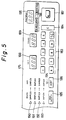
- Fig. 5 is a plan view showing one portion of a construction including the input control keys 176 and displaying means 182 on the control panel 175.
- the control panel 175 comprises numerical keys 183 for setting the number of the copies, a clear key 184, a mode selection key 185 for setting the copying mode, an ADF key 186 actuated in the case where the document is fixedly copied while being movingly scanned by the optical system, a print switch 187 for instructing a start of the copying operation, a display portion 188 for setting the number of copies, a display portion 189 for displaying the number of sets of copies having been made, copying mode indicator 190 to 193 for the recirculating document feeding apparatus 1, an ADF indicator 194 for indicating that fixedly set documents are exposingly read while the optical system is driven to scan them, a copying magnification display portion 195, and a magnification selection key 196 for selecting the copying magnification.
- These copying mode indicators 190 to 193 indicate the (simplex -> simplex) mode, (simplex -> duplex) mode, (duplex -> simplex) mode, (duplex ->duplex) mode)respectively.
- a light emitting element is lit, for example, from the above to the below and the corresponding copying mode is selected.
- the uppermost indicator is lit. In an initial state, the uppermost indicator is lit, and thereafter the desired copying mode is selected.
- the number of sets of copies are set by pressing the numerical key 183 and displayed in the display portion 188 by, for example a plurality of seven segment display devices.
- the ADF indicator 194 is lit when the ADF key 186 is pressed, and such a copying mode is selected in which the exposure means 149 is driven to scan the document placed in the third reading station 105 so as to be exposed and read.
- the operator can select the desired copying magnification by selecting any one of the standard mode, enlargement mode, and reduction mode by means of the magnification selection key 196 in the desired copying mode.
- the selected copying magnification is displayed on the copying magnification display portion 195.
- the copying operation is started and the number of sets having been copied is sequentially displayed in the display portion 189.
- the copying operation is stopped and the set number of copies automatically returns to "0". The number of copies remains to be displayed in the display portion 189, for example, until the print switch 187 is pressed next.
- the transporting speed of the documents D is set higher than the transporting speed in accordance with the minimum copying magnification. Accordingly, the counting operation is effected at high speed regardless of the selected copying magnification, thereby reducing the time required for the counting operation. More specifically, the time required for recording paper P to be discharged after the document D is placed in a document placing member 2 can be remarkably reduced, thereby improving operability of the copying machine.
- support cylinders 5, 6 and transporting rollers disposed only in the periphery of the support cylinders are controlled to be driven at maximum rotating speeds.
- all the transporting rollers for transporting the document D disposed in the recirculating document feeding apparatus 1 be controlled to be driven at high rotating speeds in case of transportation of the document D without the copying operation.
- the invention is not limited to use in the transfer-type electrostatic copying machine.
- the invention may be embodied in a copying machine in which recording paper having a photosensitive surface on one side thereof is used, or other apparatus.
Landscapes
- Physics & Mathematics (AREA)
- General Physics & Mathematics (AREA)
- Engineering & Computer Science (AREA)
- Microelectronics & Electronic Packaging (AREA)
- Exposure Or Original Feeding In Electrophotography (AREA)
- Control Or Security For Electrophotography (AREA)
- Holders For Sensitive Materials And Originals (AREA)
- Conveyance By Endless Belt Conveyors (AREA)
Claims (1)
- Kopiergerät zum Kopieren einer Bildvorlage auf Aufzeichnungspapier mit einer wählbaren Kopiervergrößerung, mit einem Vorlagenzuführgerät (1) vom Umlauftyp zum sequentiellen Transportieren von in einem Behälter (2) abgelegten Dokumentenvorlagen mit einer der gewählten Kopiervergrößerung entsprechenden Geschwindigkeit zu einer Bildlesestation (20, 21). durch die Lesestation hindurch und zurück in den Behälter (2), gekennzeichnet durch eine Steuerungseinrichtung (179) zum Einstellen der Transportgeschwindigkeit der Vorlagen auf einen höheren Wert als den der der minimalen Kopiervergrößerung entsprechenden Transportgeschwindigkeit, im Falle eines Zählvorgangs, bei dem die Vorlagen ohne Kopieren ihrer Bilder von dem Behälter (2) zu und durch die Bildlesestation (20, 21) befördert sowie zurück transportiert werden. zum Zählen der Anzahl der in dem Behälter (2) abgelegten Vorlagen.
Applications Claiming Priority (4)
| Application Number | Priority Date | Filing Date | Title |
|---|---|---|---|
| JP102638/90 | 1990-04-17 | ||
| JP10263890 | 1990-04-17 | ||
| JP3058750A JP2829142B2 (ja) | 1990-04-17 | 1991-03-22 | 循環式原稿供給装置を備える複写機 |
| JP58750/91 | 1991-03-22 |
Publications (3)
| Publication Number | Publication Date |
|---|---|
| EP0452855A2 EP0452855A2 (de) | 1991-10-23 |
| EP0452855A3 EP0452855A3 (en) | 1992-04-08 |
| EP0452855B1 true EP0452855B1 (de) | 1994-11-30 |
Family
ID=26399770
Family Applications (1)
| Application Number | Title | Priority Date | Filing Date |
|---|---|---|---|
| EP19910105977 Expired - Lifetime EP0452855B1 (de) | 1990-04-17 | 1991-04-15 | Kopiergerät mit Dokumentenzufuhrgerät vom Umlauftyp |
Country Status (3)
| Country | Link |
|---|---|
| EP (1) | EP0452855B1 (de) |
| JP (1) | JP2829142B2 (de) |
| DE (1) | DE69105335T2 (de) |
Families Citing this family (2)
| Publication number | Priority date | Publication date | Assignee | Title |
|---|---|---|---|---|
| JP4965034B2 (ja) * | 2001-08-06 | 2012-07-04 | 東北リコー株式会社 | 原稿読取装置及び印刷装置 |
| JPWO2023067709A1 (de) * | 2021-10-19 | 2023-04-27 |
Family Cites Families (4)
| Publication number | Priority date | Publication date | Assignee | Title |
|---|---|---|---|---|
| JPS6083930A (ja) * | 1983-10-14 | 1985-05-13 | Fuji Xerox Co Ltd | 原稿搬送制御装置 |
| JPS6132835A (ja) * | 1984-07-26 | 1986-02-15 | Konishiroku Photo Ind Co Ltd | 画像形成装置 |
| JPS62289859A (ja) * | 1986-06-09 | 1987-12-16 | Sharp Corp | 原稿循環送り装置付き両面複写機 |
| JPH0745311B2 (ja) * | 1988-02-15 | 1995-05-17 | シャープ株式会社 | 循環式自動原稿供給装置および該装置を備えた両面複写装置 |
-
1991
- 1991-03-22 JP JP3058750A patent/JP2829142B2/ja not_active Expired - Fee Related
- 1991-04-15 EP EP19910105977 patent/EP0452855B1/de not_active Expired - Lifetime
- 1991-04-15 DE DE1991605335 patent/DE69105335T2/de not_active Expired - Fee Related
Also Published As
| Publication number | Publication date |
|---|---|
| JP2829142B2 (ja) | 1998-11-25 |
| JPH04213570A (ja) | 1992-08-04 |
| EP0452855A3 (en) | 1992-04-08 |
| DE69105335D1 (de) | 1995-01-12 |
| EP0452855A2 (de) | 1991-10-23 |
| DE69105335T2 (de) | 1995-06-29 |
Similar Documents
| Publication | Publication Date | Title |
|---|---|---|
| JP3435264B2 (ja) | 画像形成装置 | |
| US5257064A (en) | Copying machine provided with a recirculating document feeder apparatus | |
| JPS63196457A (ja) | 用紙収納装置 | |
| US5966556A (en) | Method of duplex copying documents | |
| JP2535388B2 (ja) | 原稿供給装置を備える複写機 | |
| EP0798607A2 (de) | Kopiergerät | |
| EP0477946B1 (de) | Automatische Dokumentenzuführvorrichtung | |
| EP0452855B1 (de) | Kopiergerät mit Dokumentenzufuhrgerät vom Umlauftyp | |
| US5315360A (en) | Copying machine for copying a one-side subject copy on both sides of a copying sheet | |
| EP0548698B1 (de) | Kopiergerät | |
| JP2928358B2 (ja) | 原稿給送方法 | |
| JPH0980979A (ja) | 原稿循環装置を備えた画像形成装置 | |
| JP2501479B2 (ja) | 循環式原稿供給装置を備える複写機 | |
| JP3101147B2 (ja) | 複写機 | |
| JP2726501B2 (ja) | 複写機 | |
| JP2554748B2 (ja) | 複写機 | |
| JPH06230625A (ja) | 画像形成装置 | |
| JP2591491B2 (ja) | 自動原稿搬送装置 | |
| JP2668157B2 (ja) | 循環式原稿供給装置における原稿給紙方法 | |
| JP2620802B2 (ja) | 画像形成装置 | |
| JP3181614B2 (ja) | 両面コピー可能な画像形成装置及び方法 | |
| JP2592174B2 (ja) | 自動原稿供給装置 | |
| JP2609481B2 (ja) | シート状原稿の給送方法 | |
| JP2581626Y2 (ja) | 割り込み機能を備えた複写機 | |
| JP2695686B2 (ja) | 原稿給送装置 |
Legal Events
| Date | Code | Title | Description |
|---|---|---|---|
| PUAI | Public reference made under article 153(3) epc to a published international application that has entered the european phase |
Free format text: ORIGINAL CODE: 0009012 |
|
| 17P | Request for examination filed |
Effective date: 19910415 |
|
| AK | Designated contracting states |
Kind code of ref document: A2 Designated state(s): DE FR GB |
|
| PUAL | Search report despatched |
Free format text: ORIGINAL CODE: 0009013 |
|
| AK | Designated contracting states |
Kind code of ref document: A3 Designated state(s): DE FR GB |
|
| 17Q | First examination report despatched |
Effective date: 19930831 |
|
| GRAA | (expected) grant |
Free format text: ORIGINAL CODE: 0009210 |
|
| AK | Designated contracting states |
Kind code of ref document: B1 Designated state(s): DE FR GB |
|
| REF | Corresponds to: |
Ref document number: 69105335 Country of ref document: DE Date of ref document: 19950112 |
|
| ET | Fr: translation filed | ||
| PLBE | No opposition filed within time limit |
Free format text: ORIGINAL CODE: 0009261 |
|
| STAA | Information on the status of an ep patent application or granted ep patent |
Free format text: STATUS: NO OPPOSITION FILED WITHIN TIME LIMIT |
|
| 26N | No opposition filed | ||
| PGFP | Annual fee paid to national office [announced via postgrant information from national office to epo] |
Ref country code: FR Payment date: 20010409 Year of fee payment: 11 Ref country code: DE Payment date: 20010409 Year of fee payment: 11 |
|
| PGFP | Annual fee paid to national office [announced via postgrant information from national office to epo] |
Ref country code: GB Payment date: 20010411 Year of fee payment: 11 |
|
| REG | Reference to a national code |
Ref country code: GB Ref legal event code: IF02 |
|
| PG25 | Lapsed in a contracting state [announced via postgrant information from national office to epo] |
Ref country code: GB Free format text: LAPSE BECAUSE OF NON-PAYMENT OF DUE FEES Effective date: 20020415 |
|
| PG25 | Lapsed in a contracting state [announced via postgrant information from national office to epo] |
Ref country code: DE Free format text: LAPSE BECAUSE OF NON-PAYMENT OF DUE FEES Effective date: 20021101 |
|
| GBPC | Gb: european patent ceased through non-payment of renewal fee |
Effective date: 20020415 |
|
| PG25 | Lapsed in a contracting state [announced via postgrant information from national office to epo] |
Ref country code: FR Free format text: LAPSE BECAUSE OF NON-PAYMENT OF DUE FEES Effective date: 20021231 |
|
| REG | Reference to a national code |
Ref country code: FR Ref legal event code: ST |