EP0452271A2 - Verriegelungseinrichtung an einer Welle - Google Patents
Verriegelungseinrichtung an einer Welle Download PDFInfo
- Publication number
- EP0452271A2 EP0452271A2 EP91810252A EP91810252A EP0452271A2 EP 0452271 A2 EP0452271 A2 EP 0452271A2 EP 91810252 A EP91810252 A EP 91810252A EP 91810252 A EP91810252 A EP 91810252A EP 0452271 A2 EP0452271 A2 EP 0452271A2
- Authority
- EP
- European Patent Office
- Prior art keywords
- unlocking
- locking
- shaft
- pawl
- rotation
- Prior art date
- Legal status (The legal status is an assumption and is not a legal conclusion. Google has not performed a legal analysis and makes no representation as to the accuracy of the status listed.)
- Granted
Links
Images
Classifications
-
- B—PERFORMING OPERATIONS; TRANSPORTING
- B65—CONVEYING; PACKING; STORING; HANDLING THIN OR FILAMENTARY MATERIAL
- B65G—TRANSPORT OR STORAGE DEVICES, e.g. CONVEYORS FOR LOADING OR TIPPING, SHOP CONVEYOR SYSTEMS OR PNEUMATIC TUBE CONVEYORS
- B65G47/00—Article or material-handling devices associated with conveyors; Methods employing such devices
- B65G47/74—Feeding, transfer, or discharging devices of particular kinds or types
- B65G47/94—Devices for flexing or tilting travelling structures; Throw-off carriages
- B65G47/96—Devices for tilting links or platform
- B65G47/962—Devices for tilting links or platform tilting about an axis substantially parallel to the conveying direction
Definitions
- the invention relates to a device according to the preamble of independent claim 1.
- a locking device of this type has become known from DE-PS 30 50 102 by the applicant.
- a support plate of a distribution conveyor for general cargo is held in a horizontal rest position until it is deflected into an inclined position.
- This device requires a comparatively large drive pulley which has stop cams which interact with a central stop which acts as a catch and secures the drive pulley in its rest position until it is deflected.
- stop cams which interact with a central stop which acts as a catch and secures the drive pulley in its rest position until it is deflected.
- an additional braking device is required.
- the invention has for its object to provide a device of the type mentioned, which requires less space, has fewer components and which is still reliable and enables a more precise and secure locking.
- the object is achieved by the invention according to claim 1.
- the locking device according to the invention essentially consists of only three parts: a locking part, an unlocking part and a latch. These components are very simple and robust to implement and can be attached to the shaft to save space.
- the unlocking part has inclined surfaces which the latch deflect with a limited rotational movement of the unlocking part. With this deflection of the pawl, it is disengaged from the locking part. It has been shown that a rotary movement of only about 3 ° is sufficient to disengage the pawl.
- the pawl is deflected against the restoring force of a spring. If the load is brought back into the rest position by a rotary movement of the shaft, the spring automatically brings the catch back into the locking position.
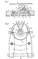
- Fig. 1 shows the structure of a carriage 2 of a known distribution conveyor for general cargo.
- the carriage 2 has four rollers 6, with which it rolls in a rail 1.
- Two guide rollers 7 take over the horizontal guidance, while the carriage 2 is driven in a known manner by an endless, revolving chain.
- the frame 10 has a bearing head 11 for an inclined axis 12, to which a support plate 3 is attached.
- the axis 12 is connected to a drive 16 via a universal joint 13 and a vertical shaft 34. With this drive 16, the shaft 34 is rotated in one direction or the other at the unloading points, whereupon the support plate 3 executes a rotary-tilting movement on one or the other side of the rail 1 and a piece goods, not shown here, slips in a collecting container.
- the support plate 3 is secured in the rest position shown until it reaches the unloading station.
- the locking direction 17 is unlocked at the unloading station and the support plate 3 is unloaded by rotating the shaft 34. After the unloading process, the Shaft 34, the support plate 3 pivoted back into the horizontal position and locked again by the device 17.
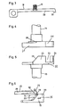
- the locking device 17 shown in FIGS. 2 to 6 has a locking part 14, an unlocking part 15 and a pawl 33.
- the shaft 34 is formed by the two parts 14 and 15 mentioned.
- the pawl 33 has two arms 18 which can be pivoted independently of one another about a horizontal axis 28 which is fixedly connected to the frame 10. Between each arm 18 and an extension 20 of the frame, a spiral spring 19 is attached, which presses the free end 30 of the corresponding arm 18 downward onto a locking disk 31 of the locking part 14. This locking disk 31 is inserted into a recess 22 of an unlocking disk 32 of the unlocking part 15.
- Two radially outwardly extending, spaced-apart cams 21 of the locking disk 31 encompass a driver cam 24 of the unlocking disk 32 such that, in the locked state according to FIG can be rotated without rotating the locking part 14.
- the locking part 14 is also rotated and the support plate 3 is pivoted in the manner mentioned.
- the unlocking part 15 is rotated clockwise as seen in the direction of rotation according to FIG. 2, the right of the two arms 18 is raised at the free end 16 before the angle ⁇ is exceeded in FIG. 2 and is thereby raised via a stop surface 26 of the locking part 14 .
- This pivoting movement of said arm 18 is controlled by an inclined surface 25 of a cam 23 arranged on the unlocking disk 32. 6 illustrates this unlocking process.
- the locked position is shown with solid lines.
- the arms 18 rest here with the front end on the locking part 14 and come into contact with a stop 26 of the locking part 14 on the front Surface 25 of the unlocking part 15 is pushed in the direction of arrow 36 upwards into the pivoted position shown in broken lines.
- the front end 30 of the arm 18 is located just above the stop surface 26, so that the unlocking part 15 can be rotated further in the direction of the arrow 35.
- the locking part 14 is also rotated in this direction of rotation by the driver cam 24, as mentioned above.
- the other of the two arms 18 (in FIG. 2 the left arm) moves away from its stop surface 26 in the circumferential direction without being pivoted. This becomes the unlocking part 15 rotated in the other direction, the left of the two arms 18 is pivoted accordingly in FIG. 2, while the right arm moves away from its stop surface 26 in the circumferential direction without being pivoted.
- the unlocking part 15 is rotated in the opposite direction until the locking part 14 reaches the position shown in Fig. 2, in which the pivoted arm by the compression spring 19 down is pivoted into the locking position.
- the interaction of the one arm 18 with the corresponding surface 25 also brings the unlocking part 15 into the symmetrical position shown in FIG. 2.
- the support plate 3 is then locked in the horizontal position and can be pivoted to the left or to the right at the next unloading station in the manner described.
- the locking device according to the invention is particularly suitable for a trolley of a distribution conveyor for general cargo.
- the support plate 3 can also perform a simple tilting movement about a horizontally extending shaft.
- the shaft 34 could then also run horizontally here.
- the invention is not limited to the application mentioned.
Landscapes
- Engineering & Computer Science (AREA)
- Mechanical Engineering (AREA)
- Discharge Of Articles From Conveyors (AREA)
- Specific Conveyance Elements (AREA)
- Clamps And Clips (AREA)
- Mechanical Control Devices (AREA)
Abstract
Description
- Die Erfindung betrifft eine Einrichtung nach dem Oberbegriff des unabhängigen Patentanspruchs 1.
- Eine Verriegelungseinrichtung dieser Art ist aus der DE-PS 30 50 102 der Anmelderin bekannt geworden. Mit dieser Einrichtung wird eine Tragplatte eines Verteilförderers für Stückgut bis zu ihrer Auslenkung in eine geneigte Lage in einer horizontalen Ruhelage gehalten. Diese Einrichtung erfordert eine vergleichsweise grosse Antriebsscheibe, die Anschlagnocken besitzt, welche mit einem mittleren Anschlag zusammenwirken, der als Raste wirkt und die Antriebsscheibe in ihrer Ruhelage sichert, bis sie ausgelenkt wird. In der Praxis hat sich zudem gezeigt, dass bei einem Verteilförderer eine zusätzliche Bremsvorrichtung erforderlich ist.
- Durch die DE-A-36 02 861 ist ebenfalls eine Verriegelungseinrichtung an einem Verteilförderer für Stückgut bekannt geworden der weitgehend dem bereits bekannten Verteilförderer entspricht. Diese Einrichtung ist in dieser Druckschrift anhand der Fig. 3 und 4 in Spalte 9, Zeile 50, bis Spalte 10, Zeile 22 erläutert. Diese Einrichtung soll hier nur schematisch dargestellte Verriegelungsmittel aufweisen, welche die Tragplatte gegen eine Drehung an einem Stützteil verriegelt. Nähere Angaben über die Verriegelungsmittel können dieser Druckschrift nicht entnommen werden.
- Der Erfindung liegt die Aufgabe zugrunde, eine Einrichtung der genannten Art zu schaffen, die weniger Raum benötigt, weniger Bauteile aufweist und die trotzdem funktionssicher ist und eine präzisere und sichere Verriegelung ermöglicht. Die Aufgabe wird durch die Erfindung gemäss Anspruch 1 gelöst. Die erfindungsgemässe Verriegelungseinrichtung besteht im wesentlichen aus lediglich drei Teilen: einem Verriegelungsteil, einem Entriegelungsteil sowie einer Klinke. Diese Bauteile sind sehr einfach und robust realisierbar und können raumsparend an der Welle angebracht werden.
- Nach einer vorteilhaften Weiterbildung der Erfindung weist der Entriegelungsteil schräge Flächen auf, welche die Klinke bei einer begrenzten Drehbewegung des Entriegelungsteils auslenken. Mit dieser Auslenkung der Klinke wird dieser ausser Eingriff mit dem Verriegelungsteil gebracht. Es hat sich gezeigt, dass hier eine Drehbewegung von lediglich etwa 3° genügt, um die Klinke ausser Eingriff zu bringen.
- Gemäss einer Weiterbildung der Erfindung wird die Klinke gegen die Rückstellkraft einer Feder ausgelenkt. Wird die Last durch eine Drehbewegung der Welle wieder in die Ruhelage gebracht, so bringt die Feder die Klinke von selbst wieder in die Verriegelungsposition. Weitere vorteilhafte Vorteile ergeben sich aus den übrigen abhängigen Ansprüche sowie der nachfolgenden Beschreibung.
- Ein Ausführungsbeispiel der Erfindung wird anhand der Zeichnungen näher erläutert. Es zeigen:
- Fig. 1 eine Seitenansicht eines Wagens eines Verteilförderers mit Kettenantrieb,
- Fig. 2 eine Draufsicht auf die Verriegelungseinrichtung,
- Fig. 3 eine Seitenansicht einer Klinke,
- Fig. 4 eine Seitenansicht eines Verriegelungsteils,
- Fig. 5 eine Seitenansicht eines Entriegelungsteils, und
- Fig. 6 eine Teilansicht der Verriegelungseinrichtung.
- Die Fig. 1 zeigt den Aufbau eines Wagens 2 eines an sich bekannten Verteilförderers für Stückgut. Der Wagen 2 besitzt vier Laufrollen 6, mit denen er in einer Schiene 1 abrollt. Zwei Führungsrollen 7 übernehmen die horizontale Führung, während der Antrieb des Wagens 2 in bekannter Weise durch eine endlose, umlaufende Kette erfolgt. Das Gestell 10 weist einen Lagerkopf 11 für eine schräge Achse 12 auf, an der eine Tragplatte 3 befestigt ist. Die Achse 12 ist über ein Kreuzgelenk 13 und eine vertikale Welle 34 mit einem Antrieb 16 verbunden. Mit diesem Antrieb 16 wird an den Entladestellen die Welle 34 in der einen oder anderen Richtung gedreht, worauf die Tragplatte 3 auf die eine oder andere Seite der Schiene 1 eine Dreh-Kippbewegung ausführt und ein hier nicht gezeigtes Stückgut in einem Sammelbehälter abrutscht.
- Mittels einer Verriegelungseinrichtung 17 wird die Tragplatte 3 in der gezeigten Ruhestellung bis zum erreichen der Entladestation gesichert. An der Entladestation wird die Verriegelungsrichtung 17 entriegelt und durch eine Drehbewegung der Welle 34 die Tragplatte 3 entladen. Nach dem Entladevorgang wird durch eine entgegengesetzte Drehbewegung der Welle 34 die Tragplatte 3 wieder in die horizontale Lage verschwenkt und selbständig durch die Einrichtung 17 wieder verriegelt.
- Die in den Fig. 2 bis 6 näher gezeigte Verriegelungseinrichtung 17 weist einen Verriegelungsteil 14, einen Entriegelungsteil 15 sowie eine Klinke 33 auf. Die Welle 34 wird durch die beiden genannten teile 14 und 15 gebildet. Die Klinke 33 besitzt zwei Arme 18, die unabhängig voneinander um eine horizontale und fest mit dem Gestell 10 verbundene Achse 28 verschwenkbar sind. Zwischen jedem Arm 18 und einem Ansatz 20 des Gestells ist eine Spiralfeder 19 angebracht, die das freie Ende 30 des entsprechenden Arms 18 nach unten auf eine Verriegelungsscheibe 31 des Verriegelungsteils 14 drückt. Diese Verriegelungsscheibe 31 ist in eine Ausnehmung 22 einer Entriegelungsscheibe 32 des Entriegelungteils 15 eingesetzt. Zwei radial sich nach aussen erstreckende, im Abstand zueinander angeordnete Nocken 21 der Verriegelungsscheibe 31 umgreifen einen Mitnehmernocken 24 der Entriegelungsscheibe 32 derart, dass im verriegelten Zustand gemäss Fig. 2 der Entriegelungsteil 15 in der einen oder anderen Drehrichtung um einen Winkel α bzw. -α gedreht werden kann, ohne hierbei den Verriegelungsteil 14 mitzudrehen. Bei einer Drehung über die genannten Winkel hinaus wird der Verriegelungsteil 14 mitgedreht und die Tragplatte 3 in der genannten Weise verschwenkt.
- Wird der Entriegelungsteil 15 in der Drehrichtung gemäss Fig. 2 gesehen im Uhrzeigersinn gedreht, so wird noch vor dem Ueberschreiten des Winkels α in Fig. 2 der rechte der beiden Arme 18 am freien Ende 16 angehoben und dabei über eine Anschlagfläche 26 des Verriegelungsteils 14 angehoben. Diese Schwenkbewegung des genannten Arms 18 wird durch eine schräge Fläche 25 eines an der Entriegelungsscheibe 32 angeordneten Nockens 23 gesteuert. Die Fig. 6 illustriert diesen Entriegelungsvorgang. In dieser Figur ist die verriegelte Position mit ausgezogenen Strichen dargestellt. Die Arme 18 ruhen hier mit dem vorderen Ende auf dem Verriegelungsteil 14 und stossen frontseitig jeweils an einen Anschlag 26 des Verriegelungsteils 14. Wird der Entriegelungsteil 15 in Richtung des Pfeiles 35 in die strichpunktiert dargestellte Lage verschwenkt, so wird der Arm 18 zwangsläufig durch die schräge Fläche 25 des Entriegelungsteils 15 in Richtung des Pfeiles 36 nach oben in die strichpunktiert gezeigte Schwenklage geschoben. In dieser Position befindet sich das vordere Ende 30 des Arms 18 knapp über der Anschlagefläche 26, so dass der Entriegelungsteil 15 weiter in Richtung des Pfeils 35 gedreht werden kann. Nach dem Ueberschreiten des Winkels α wird wie oben erwähnt durch den Mitnehmernocken 24 auch der Verriegelungsteil 14 in dieser Drehrichtung mitgedreht. Der andere der beiden Arme 18 (in Fig. 2 der linke Arm) entfernt sich ohne verschwenkt zu werden in Umfangsrichtung von seiner Anschlagfläche 26. Wird der Entriegelungsteil 15 in der anderen Richtung gedreht, so wird entsprechend in Fig. 2 der linke der beiden Arme 18 verschwenkt, während der rechte Arm ohne verschwenkt zu werden sich in Umfangsrichtung von seiner Anschlagfläche 26 entfernt.
- Soll die Tragplatte 3 wieder in die horizontale Position zurückgeschwenkt und verriegelt werden, so wird der Entriegelungsteil 15 in entgegengesetzter Drehrichtung so weit gedreht, bis der Verriegelungsteil 14 die in Fig. 2 gezeigte Stellung erreicht, in welcher der verschwenkte Arm durch die Druckfeder 19 nach unten in die verriegelnde Position verschwenkt wird. Wie ohne weiteres ersichtlich, wird durch das Zuammenwirken des einen Armes 18 mit der entsprechenden Fläche 25 auch der Entriegelungsteil 15 in die in Fig. 2 gezeigte symmetrische Lage gebracht. In dieser ist dann die Tragplatte 3 in der horizontalen Lage verriegelt und kann an der nächsten Entladestation in der geschilderten Weise nach links oder nach rechts verschwenkt werden.
- Die erfindungsgemässe Verriegelungseinrichtung eignet sich besonders für einen Wagen eines Verteilförderers für Stückgut. Die Tragplatte 3 kann hierbei auch eine einfache Kippbewegung um eine horizontal verlaufende Welle ausführen. Entsprechend könnte hier die Welle 34 dann auch horizontal verlaufen. Die Erfindung ist jedoch nicht auf die genannte Anwendung beschränkt.
Claims (5)
- Verriegelungseinrichtung an einer drehbar gelagerten und mit einem Antrieb (16) verbundenen Welle (12), wobei die Einrichtung die Welle (12) bezüglich eines Gestells (10) in beiden Drehrichtungen lösbar gegen ein von einer Last (3) ausgehendes Verdrehen sichert, dadurch gekennzeichnet, dass die Welle (12) einen mit der Last (3) verbundenen Verriegelungsteil (14) und einen mit dem Antrieb (16) verbundenen Entriegelungsteil (15) aufweist, dass in einer Ruhestellung der Entriegelungsteil (15) in beiden Drehrichtungen bezüglich des Verriegelungsteils (14) begrenzt verdrehbar ist und dass der Entriegelungsteil (15) während einer solchen begrenzten Drehbewegung eine mit dem Gestell (10) verbundene Klinke (18) vom Verriegelungsteil (14) abhebt und dadurch die Welle (12) entriegelt.
- Einrichtung nach Anspruch 1, dadurch gekennzeichnet, dass der Entriegelungsteil (15) schräge Flächen (25) aufweist, an welchen die Klinke (33) bei einer begrenzten Drehbewegung des Entriegelungsteil (15) ausgelenkt und ausser Eingriff mit dem Verriegelungsteil (14) gebracht wird.
- Einrichtung nach Anspruch 1 oder 2, dadurch gekennzeichnet, dass die Klinke (33) zwei Arme (18) aufweist, die jeweils mit einer schrägen Fläche (25) zusammenwirken und die jeweils die Welle (12) in einer Drehrichtung verriegeln.
- Einrichtung nach einem der Ansprüche 1 bis 3, dadurch gekennzeichnet, dass beim Entriegeln die Klinke (33) gegen die Kraft wenigstens einer Feder (19) verschwenkt wird.
- Einrichtung nach einem der Ansprüche 1 bis 4, dadurch gekennzeichnet, dass der Verriegelungsteil (14) und der Entriegelungsteil (15) jeweils eine sich zur Längsrichtung der Welle radial erstreckende Verriegelungsscheibe (31) bzw. Entriegelungsscheibe (32) aufweisen, wobei ein Mitnehmernocken (24) der einen Scheibe in eine Ausnehmung der anderen Scheibe derart eingreift, dass in der Ruhestellung der Entriegelungsteil (15) in beiden Drehrichtungen um einen Winkel (α,-α) bis zum Anschlag des Mitnehmernockens (24) drehbar ist.
Applications Claiming Priority (2)
| Application Number | Priority Date | Filing Date | Title |
|---|---|---|---|
| CH1240/90A CH680284A5 (de) | 1990-04-11 | 1990-04-11 | |
| CH1240/90 | 1990-04-11 |
Publications (3)
| Publication Number | Publication Date |
|---|---|
| EP0452271A2 true EP0452271A2 (de) | 1991-10-16 |
| EP0452271A3 EP0452271A3 (en) | 1992-08-12 |
| EP0452271B1 EP0452271B1 (de) | 1995-08-09 |
Family
ID=4205757
Family Applications (1)
| Application Number | Title | Priority Date | Filing Date |
|---|---|---|---|
| EP91810252A Expired - Lifetime EP0452271B1 (de) | 1990-04-11 | 1991-04-05 | Verriegelungseinrichtung an einer Welle |
Country Status (6)
| Country | Link |
|---|---|
| US (1) | US5092437A (de) |
| EP (1) | EP0452271B1 (de) |
| JP (1) | JPH0672536A (de) |
| CH (1) | CH680284A5 (de) |
| DE (1) | DE59106178D1 (de) |
| ES (1) | ES2077833T3 (de) |
Cited By (1)
| Publication number | Priority date | Publication date | Assignee | Title |
|---|---|---|---|---|
| US5348132A (en) * | 1992-07-30 | 1994-09-20 | Grapha-Holding Ag | Carriage for a conveyor for piece goods |
Families Citing this family (1)
| Publication number | Priority date | Publication date | Assignee | Title |
|---|---|---|---|---|
| US5695030A (en) * | 1995-10-16 | 1997-12-09 | Applied Kinetics Corporation | Park mechanism for automotive transmission |
Family Cites Families (5)
| Publication number | Priority date | Publication date | Assignee | Title |
|---|---|---|---|---|
| US2066167A (en) * | 1932-07-18 | 1936-12-29 | Guy E Swartz | Shaft operating and locking device |
| FR1349737A (fr) * | 1963-03-05 | 1964-01-17 | Plessey Co Ltd | Dispositif d'accouplement pour mécanismes d'entraînement |
| US3366752A (en) * | 1966-02-25 | 1968-01-30 | Honeywell Inc | Control apparatus |
| CH642326A5 (de) * | 1980-01-04 | 1984-04-13 | Daverio Ag | Verteilfoerderer fuer stueckgut. |
| DE3602861A1 (de) * | 1986-01-31 | 1987-08-13 | Beumer Maschf Bernhard | Kipp-foerderelement fuer einen stueckgutfoerderer |
-
1990
- 1990-04-11 CH CH1240/90A patent/CH680284A5/de not_active IP Right Cessation
-
1991
- 1991-03-28 US US07/676,843 patent/US5092437A/en not_active Expired - Fee Related
- 1991-04-05 DE DE59106178T patent/DE59106178D1/de not_active Expired - Fee Related
- 1991-04-05 ES ES91810252T patent/ES2077833T3/es not_active Expired - Lifetime
- 1991-04-05 EP EP91810252A patent/EP0452271B1/de not_active Expired - Lifetime
- 1991-04-11 JP JP3079289A patent/JPH0672536A/ja active Pending
Cited By (1)
| Publication number | Priority date | Publication date | Assignee | Title |
|---|---|---|---|---|
| US5348132A (en) * | 1992-07-30 | 1994-09-20 | Grapha-Holding Ag | Carriage for a conveyor for piece goods |
Also Published As
| Publication number | Publication date |
|---|---|
| US5092437A (en) | 1992-03-03 |
| EP0452271B1 (de) | 1995-08-09 |
| EP0452271A3 (en) | 1992-08-12 |
| CH680284A5 (de) | 1992-07-31 |
| DE59106178D1 (de) | 1995-09-14 |
| JPH0672536A (ja) | 1994-03-15 |
| ES2077833T3 (es) | 1995-12-01 |
Similar Documents
| Publication | Publication Date | Title |
|---|---|---|
| EP0077489B1 (de) | Vorrichtung zum Zusammensetzen zweier ineinander-schiebbarer Teile, von denen eines wenigstens einen radial gerichteten Vorsprung aufweist | |
| DE2518334B1 (de) | Bogentragscheibe fuer bogenueberfuehrungstrommeln | |
| DE69001613T2 (de) | Vorrichtung zum Aufhängen eines Tochtergeschosses an geneigter Position unter einen Fallschirm. | |
| EP0845385A2 (de) | Umklappbare Hintersitz-Rückenlehne für Kraftfahrzeuge | |
| EP0452271A2 (de) | Verriegelungseinrichtung an einer Welle | |
| DE1456538A1 (de) | Vorrichtung zur auswechselbaren Halterung von Arbeitsgeraeten an Lademaschinen | |
| DE2322110A1 (de) | Anlage zum reinigen von fahrzeugen, insbesondere kraftwagen | |
| DE3210723C2 (de) | Farbbandhubvorrichtung für Schreib- oder ähnliche Maschinen | |
| CH639709A5 (de) | Rotations-schaftmaschine. | |
| DE2819068B2 (de) | Vorrichtung zur Steuerung von Weichen bei einer Hängebahn mit Fahrwerken | |
| EP0218795B1 (de) | Verstelleinrichtung für Skibindungen | |
| DE2012697C3 (de) | Antriebsgelenkkettenanordnung | |
| EP0118722B1 (de) | Kippascher, insbesondere für Fahrzeuge | |
| DE3200540C2 (de) | Vorrichtung zum Verschließen von Behältern mit Stöpseln | |
| DE2545373C2 (de) | Vorrichtung zum Verändern der Anschlagstärke eines Typenkopfes in kraftangetriebenen Schreibmaschinen | |
| DE1780520A1 (de) | Sitz,insbesondere Kraftfahrzeugsitz | |
| DE3103265A1 (de) | Vorrichtung an einem foerderer | |
| DE158763C (de) | ||
| DE2315153A1 (de) | Zweiseitige einrichtung zur betaetigung des verschlusses einer automatischen kupplung von schienenfahrzeugen | |
| DE335766C (de) | Sperrvorrichtung zur Verhinderung unbeabsichtigter Hoehenverstellung der Schreibwalze | |
| DE2919039C2 (de) | Vorrichtung zum lösbaren Festsetzen von Sichtgeräten für gepanzerte Fahrzeuge | |
| DE3338818C2 (de) | Vorrichtung zum Stabilisieren einer Außenlast | |
| DE2006942C (de) | Möbel mit mindestens einem Träger oder Tragarm, der an einer seiner Seiten mit einem aufrecht angeordneten Möbelteil leicht lösbar verbunden ist | |
| CH660570A5 (de) | Verriegelungsanordnung in einem druckapparat fuer elektrische bueromaschinen. | |
| DE2424388C2 (de) | Batteriewechselvorrichtung für batteriegetriebene Fahrzeuge |
Legal Events
| Date | Code | Title | Description |
|---|---|---|---|
| PUAI | Public reference made under article 153(3) epc to a published international application that has entered the european phase |
Free format text: ORIGINAL CODE: 0009012 |
|
| AK | Designated contracting states |
Kind code of ref document: A2 Designated state(s): DE ES FR GB IT NL SE |
|
| PUAL | Search report despatched |
Free format text: ORIGINAL CODE: 0009013 |
|
| AK | Designated contracting states |
Kind code of ref document: A3 Designated state(s): DE ES FR GB IT NL SE |
|
| 17P | Request for examination filed |
Effective date: 19920929 |
|
| RAP1 | Party data changed (applicant data changed or rights of an application transferred) |
Owner name: MUELLER MARTINI VERSAND-SYSTEME AG |
|
| 17Q | First examination report despatched |
Effective date: 19940325 |
|
| RAP1 | Party data changed (applicant data changed or rights of an application transferred) |
Owner name: GRAPHA-HOLDING AG |
|
| GRAA | (expected) grant |
Free format text: ORIGINAL CODE: 0009210 |
|
| AK | Designated contracting states |
Kind code of ref document: B1 Designated state(s): DE ES FR GB IT NL SE |
|
| REF | Corresponds to: |
Ref document number: 59106178 Country of ref document: DE Date of ref document: 19950914 |
|
| ITF | It: translation for a ep patent filed | ||
| GBT | Gb: translation of ep patent filed (gb section 77(6)(a)/1977) |
Effective date: 19951009 |
|
| REG | Reference to a national code |
Ref country code: ES Ref legal event code: FG2A Ref document number: 2077833 Country of ref document: ES Kind code of ref document: T3 |
|
| ET | Fr: translation filed | ||
| PLBE | No opposition filed within time limit |
Free format text: ORIGINAL CODE: 0009261 |
|
| 26N | No opposition filed | ||
| PGFP | Annual fee paid to national office [announced via postgrant information from national office to epo] |
Ref country code: GB Payment date: 20010326 Year of fee payment: 11 |
|
| PGFP | Annual fee paid to national office [announced via postgrant information from national office to epo] |
Ref country code: SE Payment date: 20010411 Year of fee payment: 11 |
|
| REG | Reference to a national code |
Ref country code: GB Ref legal event code: 732E |
|
| PGFP | Annual fee paid to national office [announced via postgrant information from national office to epo] |
Ref country code: FR Payment date: 20010420 Year of fee payment: 11 |
|
| PGFP | Annual fee paid to national office [announced via postgrant information from national office to epo] |
Ref country code: ES Payment date: 20010427 Year of fee payment: 11 |
|
| PGFP | Annual fee paid to national office [announced via postgrant information from national office to epo] |
Ref country code: NL Payment date: 20010430 Year of fee payment: 11 |
|
| PGFP | Annual fee paid to national office [announced via postgrant information from national office to epo] |
Ref country code: DE Payment date: 20010620 Year of fee payment: 11 |
|
| REG | Reference to a national code |
Ref country code: FR Ref legal event code: TP |
|
| NLS | Nl: assignments of ep-patents |
Owner name: SIEMENS AKTIENGESELLSCHAFT |
|
| REG | Reference to a national code |
Ref country code: ES Ref legal event code: PC2A |
|
| REG | Reference to a national code |
Ref country code: GB Ref legal event code: IF02 |
|
| PG25 | Lapsed in a contracting state [announced via postgrant information from national office to epo] |
Ref country code: GB Free format text: LAPSE BECAUSE OF NON-PAYMENT OF DUE FEES Effective date: 20020405 |
|
| PG25 | Lapsed in a contracting state [announced via postgrant information from national office to epo] |
Ref country code: SE Free format text: LAPSE BECAUSE OF NON-PAYMENT OF DUE FEES Effective date: 20020406 Ref country code: ES Free format text: LAPSE BECAUSE OF NON-PAYMENT OF DUE FEES Effective date: 20020406 |
|
| PG25 | Lapsed in a contracting state [announced via postgrant information from national office to epo] |
Ref country code: NL Free format text: LAPSE BECAUSE OF NON-PAYMENT OF DUE FEES Effective date: 20021101 Ref country code: DE Free format text: LAPSE BECAUSE OF NON-PAYMENT OF DUE FEES Effective date: 20021101 |
|
| EUG | Se: european patent has lapsed |
Ref document number: 91810252.6 |
|
| GBPC | Gb: european patent ceased through non-payment of renewal fee |
Effective date: 20020405 |
|
| PG25 | Lapsed in a contracting state [announced via postgrant information from national office to epo] |
Ref country code: FR Free format text: LAPSE BECAUSE OF NON-PAYMENT OF DUE FEES Effective date: 20021231 |
|
| NLV4 | Nl: lapsed or anulled due to non-payment of the annual fee |
Effective date: 20021101 |
|
| REG | Reference to a national code |
Ref country code: FR Ref legal event code: ST |
|
| REG | Reference to a national code |
Ref country code: ES Ref legal event code: FD2A Effective date: 20030514 |
|
| PG25 | Lapsed in a contracting state [announced via postgrant information from national office to epo] |
Ref country code: IT Free format text: LAPSE BECAUSE OF NON-PAYMENT OF DUE FEES Effective date: 20050405 |