EP0451828B1 - Appareil d'enregistrement - Google Patents
Appareil d'enregistrement Download PDFInfo
- Publication number
- EP0451828B1 EP0451828B1 EP91105708A EP91105708A EP0451828B1 EP 0451828 B1 EP0451828 B1 EP 0451828B1 EP 91105708 A EP91105708 A EP 91105708A EP 91105708 A EP91105708 A EP 91105708A EP 0451828 B1 EP0451828 B1 EP 0451828B1
- Authority
- EP
- European Patent Office
- Prior art keywords
- recording
- recording apparatus
- passage
- vertical
- recording medium
- Prior art date
- Legal status (The legal status is an assumption and is not a legal conclusion. Google has not performed a legal analysis and makes no representation as to the accuracy of the status listed.)
- Expired - Lifetime
Links
Images


Classifications
-
- F—MECHANICAL ENGINEERING; LIGHTING; HEATING; WEAPONS; BLASTING
- F16—ENGINEERING ELEMENTS AND UNITS; GENERAL MEASURES FOR PRODUCING AND MAINTAINING EFFECTIVE FUNCTIONING OF MACHINES OR INSTALLATIONS; THERMAL INSULATION IN GENERAL
- F16M—FRAMES, CASINGS OR BEDS OF ENGINES, MACHINES OR APPARATUS, NOT SPECIFIC TO ENGINES, MACHINES OR APPARATUS PROVIDED FOR ELSEWHERE; STANDS; SUPPORTS
- F16M13/00—Other supports for positioning apparatus or articles; Means for steadying hand-held apparatus or articles
- F16M13/005—Other supports for positioning apparatus or articles; Means for steadying hand-held apparatus or articles integral with the apparatus or articles to be supported
-
- B—PERFORMING OPERATIONS; TRANSPORTING
- B41—PRINTING; LINING MACHINES; TYPEWRITERS; STAMPS
- B41J—TYPEWRITERS; SELECTIVE PRINTING MECHANISMS, i.e. MECHANISMS PRINTING OTHERWISE THAN FROM A FORME; CORRECTION OF TYPOGRAPHICAL ERRORS
- B41J11/00—Devices or arrangements of selective printing mechanisms, e.g. ink-jet printers or thermal printers, for supporting or handling copy material in sheet or web form
- B41J11/0045—Guides for printing material
- B41J11/005—Guides in the printing zone, e.g. guides for preventing contact of conveyed sheets with printhead
-
- B—PERFORMING OPERATIONS; TRANSPORTING
- B41—PRINTING; LINING MACHINES; TYPEWRITERS; STAMPS
- B41J—TYPEWRITERS; SELECTIVE PRINTING MECHANISMS, i.e. MECHANISMS PRINTING OTHERWISE THAN FROM A FORME; CORRECTION OF TYPOGRAPHICAL ERRORS
- B41J11/00—Devices or arrangements of selective printing mechanisms, e.g. ink-jet printers or thermal printers, for supporting or handling copy material in sheet or web form
- B41J11/48—Apparatus for condensed record, tally strip, or like work using two or more papers, or sets of papers, e.g. devices for switching over from handling of copy material in sheet form to handling of copy material in continuous form and vice versa or point-of-sale printers comprising means for printing on continuous copy material, e.g. journal for tills, and on single sheets, e.g. cheques or receipts
-
- B—PERFORMING OPERATIONS; TRANSPORTING
- B41—PRINTING; LINING MACHINES; TYPEWRITERS; STAMPS
- B41J—TYPEWRITERS; SELECTIVE PRINTING MECHANISMS, i.e. MECHANISMS PRINTING OTHERWISE THAN FROM A FORME; CORRECTION OF TYPOGRAPHICAL ERRORS
- B41J13/00—Devices or arrangements of selective printing mechanisms, e.g. ink-jet printers or thermal printers, specially adapted for supporting or handling copy material in short lengths, e.g. sheets
- B41J13/10—Sheet holders, retainers, movable guides, or stationary guides
- B41J13/12—Sheet holders, retainers, movable guides, or stationary guides specially adapted for small cards, envelopes, or the like, e.g. credit cards, cut visiting cards
-
- B—PERFORMING OPERATIONS; TRANSPORTING
- B41—PRINTING; LINING MACHINES; TYPEWRITERS; STAMPS
- B41J—TYPEWRITERS; SELECTIVE PRINTING MECHANISMS, i.e. MECHANISMS PRINTING OTHERWISE THAN FROM A FORME; CORRECTION OF TYPOGRAPHICAL ERRORS
- B41J29/00—Details of, or accessories for, typewriters or selective printing mechanisms not otherwise provided for
- B41J29/02—Framework
-
- B—PERFORMING OPERATIONS; TRANSPORTING
- B41—PRINTING; LINING MACHINES; TYPEWRITERS; STAMPS
- B41J—TYPEWRITERS; SELECTIVE PRINTING MECHANISMS, i.e. MECHANISMS PRINTING OTHERWISE THAN FROM A FORME; CORRECTION OF TYPOGRAPHICAL ERRORS
- B41J3/00—Typewriters or selective printing or marking mechanisms characterised by the purpose for which they are constructed
- B41J3/36—Typewriters or selective printing or marking mechanisms characterised by the purpose for which they are constructed for portability, i.e. hand-held printers or laptop printers
-
- F—MECHANICAL ENGINEERING; LIGHTING; HEATING; WEAPONS; BLASTING
- F16—ENGINEERING ELEMENTS AND UNITS; GENERAL MEASURES FOR PRODUCING AND MAINTAINING EFFECTIVE FUNCTIONING OF MACHINES OR INSTALLATIONS; THERMAL INSULATION IN GENERAL
- F16M—FRAMES, CASINGS OR BEDS OF ENGINES, MACHINES OR APPARATUS, NOT SPECIFIC TO ENGINES, MACHINES OR APPARATUS PROVIDED FOR ELSEWHERE; STANDS; SUPPORTS
- F16M11/00—Stands or trestles as supports for apparatus or articles placed thereon Stands for scientific apparatus such as gravitational force meters
- F16M11/20—Undercarriages with or without wheels
- F16M11/22—Undercarriages with or without wheels with approximately constant height, e.g. with constant length of column or of legs
-
- F—MECHANICAL ENGINEERING; LIGHTING; HEATING; WEAPONS; BLASTING
- F16—ENGINEERING ELEMENTS AND UNITS; GENERAL MEASURES FOR PRODUCING AND MAINTAINING EFFECTIVE FUNCTIONING OF MACHINES OR INSTALLATIONS; THERMAL INSULATION IN GENERAL
- F16M—FRAMES, CASINGS OR BEDS OF ENGINES, MACHINES OR APPARATUS, NOT SPECIFIC TO ENGINES, MACHINES OR APPARATUS PROVIDED FOR ELSEWHERE; STANDS; SUPPORTS
- F16M2200/00—Details of stands or supports
- F16M2200/08—Foot or support base
Definitions
- the present invention relates to a recording apparatus for recording onto a recording sheet based on image information.
- a recording apparatus such as a printer, a copying machine and a facsimile terminal equipment is constituted to record an image consisting of dot patterns onto a sheet-like recording medium (thereafter referred to as a recording sheet) such as paper or plastic thin board, by driving energy generation means of recording head, based on image information.
- a recording sheet such as paper or plastic thin board
- the recording apparatus can be classified into the ink jet printing, wire dot-matrix printing, thermal recording and laser beam printing systems, according to the method or recording.
- a recording sheet useful for recording there is a thick paper such as an envelope or postcard, or a special sheet such as a plastic thin board, as well as a plain paper.
- the recording apparatus which is generally a horizontal type, has an insertion opening and an exhaustion opening for recording sheet which are provided on an upper face of recording apparatus.
- a recording sheet inserted through the insertion opening is recorded while being conveyed along a recording sheet conveyance passage constructed as a U-shape, and then exhausted through the exhaustion opening after recording.
- a recording apparatus in which an insertion opening for thick paper or special sheet is provided on an under face of apparatus to make its conveyance passage straight-like, whereby recording sheet such as a thick paper can be also conveyed smoothly.
- the insertion opening for recording sheet is provided on upper and lower (bottom) faces, and the exhaustion opening for recording sheet is provided on an upper face.
- the recording apparatus having the insertion opening for recording sheet on upper and lower faces has two service positions (attitudes), i.e., horizontal and vertical, depending on the insertion direction of recording sheet, and in order to be stable in either position, an external shape of recording apparatus must be almost cube with the approximately same depth and height, resulting in a waste space in the interior.
- the recording apparatus like a printer useful as an output apparatus is also demanded to be made small-sized and at lower cost.
- GB-A-2 196 300 discloses a recording apparatus having the features of the preamble of claim 1.
- the invention provides a recording apparatus according to claim 1.
- the invention provides a recording apparatus for recording onto a recording sheet based on image information, wherein the recording apparatus can be used stably in either of the horizontal and vertical recording positions, and allows the reduction of the overall size, simplification of structure, and reduction of cost, by providing an insertion opening for recording sheet on the identical and opposite sides to an exhaustion opening for recording sheet and providing a rotatable support saddle on a back portion of the recording apparatus.
- the invention provides an ink jet recording apparatus using an ink jet recording head and having a battery mechanism, which can maintain the stable position, wherein it is constituted to have a rotatable support saddle on an external surface of recording apparatus on the side of battery mechanism storage portion so as to place the center of gravity substantially and surely in a lower location in the vertical position.
- the invention provides an ink jet recording apparatus having an ink jet recording head and a battery mechanism, wherein it can perform the stable recording in either of the vertical and horizontal recording position for the apparatus, by providing a support saddle on the side of battery mechanism thereby to resolve misoperation problem resulting from the advantage of having no limitations in the position of ink jet recording head.
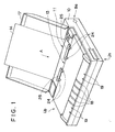
- Fig. 1 is a perspective view showing a recording apparatus 10 according to one example of the present invention, in the horizontal recording position
- Fig. 2 is a perspective view showing a back portion of the recording apparatus 10 as shown in Fig. 1.
- Fig. 3 is a perspective view showing the recording apparatus 10 as shown in Fig. 1, in the vertical recording position.
- Fig. 4 is a longitudinal cross-sectional view showing an internal construction of the apparatus 10 as shown in Fig. 3, in the vertical recording position.
- the recording apparatus 10 is an ink jet recording apparatus with the ink jet recording method for recording an image onto a recording sheet 14 by discharging the ink through discharge ports of a recording head by the use of electricity-heat converters for forming ink liquid droplets.
- the recording apparatus 10 of this example is normally used in the horizontal position (as shown in Fig. 1), while in the vertical position, it is used in the standing position with a back portion Ba being placed on the under face and an upper face Up as the front face.
- a first insertion opening for recording sheet 11 and an exhaustion opening for recording sheet 13 are provided on the upper face Up of the recording apparatus 10.
- a recording sheet 14 inserted through the first insertion opening for recording sheet 11 is closely carried on a peripheral surface of platen roller 15 (Fig. 4) which is also used as sheet feed roller, and conveyed in the direction of the arrow A along a first recording sheet conveyance passage S1. That is, as shown in Fig. 4, the recording sheet manually inserted from an upper cover 17b through the sheet insertion opening 11 is conveyed by the platen roller 15 and exhausted through the sheet exhaustion opening 13.
- the above mentioned recording sheet 14 inserted through the sheet insertion opening 11 passes through a position opposed to recording head 16 (Fig. 4), where an image is recorded by the recording head 16, and is exhausted upward (forward in the vertical type) through the sheet exhaustion opening 13 after recording.
- the upper cover 17 is fitted, in an openable or closable manner, into place on an upper face of the recording apparatus 10, where it is used as a paper feed tray or exhaustion tray in an open state during recording, as shown in Fig. 1, and is set to a closed position during non-recording (reverse or storage) as shown in Fig. 2.
- the upper cover 17 covers and protects an upper face Up of recording apparatus 10 in the closed state, in which the first recording sheet insertion opening 11, the recording sheet exhaustion opening 13, switches 18, a display 19 and so on are disposed.
- the recording head 16 is mounted on a carriage 22 movable in a reciprocatory motion along guide shafts 20, 21 parallel to the platen roller 15.
- the recording head is shown as an ink jet recording head, in which an ink tank for storing the ink and the head are integrally formed as an exchangeable head cartridge for the recording apparatus 10. Also, the recording head 16 may be formed separately from the ink tank.
- the ink jet recording head 16 is a recording head for discharging the ink by the use of the heat energy with electricity-heat converters for generating the heat energy.
- the ink jet recording head 16 makes the recording by discharging the ink through the discharge ports by growth of bubbles owing to film boiling caused by the heat energy applied by the electricity-heat converters.
- a sheet presser plate 23 for pressing a recording sheet 14 against the platen roller 15 is placed upstream of the recording head 16 in the conveyance direction, and elastically biased onto a periphery of platen roller 15 by means of a spring 35 provided between main body of apparatus and the presser plate 23.
- a spur 24 having teeth around its periphery and an exhaustion roller 25 to aid in the exhaustion of recording sheet 14 are disposed in the recording sheet exhaustion opening 13.
- a second recording sheet insertion opening 12 is provided on the rear face Un (back face in the vertical position) of the recordings apparatus 10. And a second recording sheet conveyance passage S2 is formed in substantially straight shape, leading from the recording sheet insertion opening 12 through a recording portion R between the recording head 16 and the platen roller 15 to the recording sheet exhaustion opening 13.
- This second recording sheet conveyance passage S2 can easily feed a nervy recording sheet 26, such as a thick recording sheet such as a postcard or envelope, or a special recording sheet as a plastic sheet, because of its substantially straight shape
- the recording sheet or special recording sheet 26 is inserted in the direction of the arrow B as indicated in Fig. 3, passed through the recording portion R, exhausted out of the recording sheet exhaustion opening 13, and stacked onto a paper exhaustion tray formed by the upper cover 17 placed in the open state around an axis 17a.
- a support saddle 28 is mounted to be rotatable (for storage and overhang) on a back portion Ba (or an under face Un in the vertical position shown in Figs. 3 and 4) of the recording apparatus 10.
- the support saddle 28 is rotatably mounted around an axis 29 within a recess 36 depressed by almost a thickness of support saddle 28 which is provided on the back portion Ba.
- the support saddle 28 When the recording apparatus 10 is used in the vertical position, the support saddle 28 is rotated to the overhang position where it is approximately orthogonal to the body of recording apparatus 10. Thereby, the recording apparatus 10 can be stably supported in the vertical position, and can be placed in a stale condition for inserting the recording sheet 14, or operating the switches 18.
- the support saddle 28 is rotated into a withdrawal position almost parallel to the recording apparatus 10, as shown in Fig. 2, so that the support saddle 28 can be set to the state where it is no obstacle to the recording apparatus 10 in the horizontal position, thereby not impeding the storage or transport.
- the support saddle 28 provided on the back portion Ba of recording apparatus 10 serves as a backup for a battery cover 30 for carrying a battery 27 contained in the back portion Ba of the apparatus, so that the battery cover 30 detachable from the main body can not be easily disengaged due to the vibration or impact.
- the battery 27 serves as a driving source for the heat driving of the ink jet recording head 16 or the serial reciprocation driving in recording, or recovery means for performing well-known head recovery processsing such as suction or pressure recovery, cleaning, etc., in accordance with the timer for deciding the non-use period or its decision result, when the apparatus is left unused for a long time or intermittently used.
- the battery 27 may be a battery mechanism such as an accumulator or solar battery as well as battery.
- this example is a recording apparatus using the ink jet recording head 16 and the battery mechanism 27, wherein in the horizontal recording position, the battery mechanism 27 is arranged to place its large surface (back portion Un) of almost rectangular parallelopiped on the bottom face, as seen from Fig. 2, so that the apparatus can be used stably without substantially changing the center of gravity.
- the support saddle 28 provided in the vicinity of the battery mechanism as seen from Fig. 4, an operator can use the apparatus with the support saddle 28 placed on the bottom without false operation, whereby the recording is performed with the center of gravity being necessarily placed in a lower part of the apparatus 10.
- the support saddle 28 serves to put the apparatus into an extremely stable state due to the cooperation with the battery mechanism 27.
- end portions 281, 282 of support saddle 28 in the longitudinal direction are shaped like circular arcs, as shown in Fig. 2. This contour is intended to distribute evenly the load applied thereto from the outside and absorb it all over the surface of support saddle 28.
- This circular arc shape is one in which the end portion 282 has a radius R1, and the end portion 281 a the radius R2, with the center of rotation in the support saddle 28.
- the rotatable support saddle 28 is preferably made of the same material as that for the main body of apparatus, and it is more preferred that in the vertical position, the support saddle is held crosswise to the apparatus body on the central portion thereof, while in the horizontal position, it is held accommodated within an external face of the apparatus body.
- a well-known stop mechanism is used in which a combination of a rib for stopping the rotation and a rib which is ridden over by the support saddle but serves as a stop with a slight amount of working force or a hook mechanism is applicable.
- Fig. 4 above the support saddle 28 forming the under face, there is shown the battery mechanism 27, above which are located a conveyance mechanism such as platen roller 15, and further the ink jet recording head 16 in a downwardly directed recording form (for discharging the ink downwardly), with the center C of the apparatus body 10 with height 2L being located at the ink tank 16a for recording head 16.
- the ink jet recording head 16 when the ink jet recording head 16 is formed as a disposable or replaceable type, the amount of ink storage within the ink tank 16a is decreased during the consumption for recording, while most of the weight of whole apparatus is located lower than the center C, so that the vertical recording position can be made more stable.
- the recording sheet insertion openings 11, 12 are provided on an upper face Up and an under face Un of recording apparatus 10, and the recording sheet exhaustion opening 13 is provided on the upper face Up of recording apparatus 10. Also, the recording sheet insertion openings 11, 12 are provided on identical and opposite faces to the recording sheet exhaustion opening 13, respectively, and the rotatable support saddle 28 is provided on a back portion of the recording apparatus 10.
- the recording apparatus 10 can be operated stably even when used in the vertical position, with an extremely simple, compact and inexpensive construction.
- the support saddle 28 When the apparatus is used in the stable horizontal position, the support saddle 28 is no obstacle without projecting out of the apparatus body because it can be contained within the recess 36, whereby the apparatus which can be placed in very compact and convenient state for receiving, storing or transporting of the apparatus 10 has been obtained.
- the support saddle 28 is constituted to be rotatably carried about the axis 29 of the apparatus 10, whereas it can be constituted such that a portion corresponding to the axis 29 is formed integrally with the support saddle 28, using a plastic, and is rotatably fitted forcedly into the apparatus 10 with the elasticity of the plastic. With such a constitution, a further reduction of cost can be achieved.
- one support saddle 28 is mounted, but two or more same support saddles can be mounted.
- the length of support saddle can be shortened, and the occupation area of the apparatus 10 in the vertical position can be further reduced, so that the space efficiency in the use of apparatus is improved, and the stability of the apparatus 10 can be increased.
- the present invention is applied to an ink jet recording apparatus, it should be understood that the present invention is similarly applicable to other type recording apparatus such as the wire-dot printing or thermal imprint recording method and can thereby accomplish the same effects.
- the present invention is applied to a serial scanning type recording apparatus using a recording head in a so-called serial scan method where the recording head 16 is moutned on carriage 22, it should be understood that the present invention is also applicable to a recording apparatus with other recording method, such as a line type recording apparatus using a line type recording head which covers recording area in the direction of paper width for a recording medium, and can accomplish the same action effects.
- the present invention is similarly applicable to a recording apparatus using a plurality of recording heads such as a color recording apparatus, irrespective of the number of recording heads, and can accomplish the same effects.
- the ink jet recording apparatus will be described in more detail in which the recording is performed by discharging the ink through the discharge ports by the use of the heat energy of electricity-heat converters as the energy for recording.
- This system is applicable to either of the so-called on-demand type and the continuous type.
- the case of the on-demand type is effective because, by applying at least one driving signal which gives rapid temperature elevation exceeding nucleus boiling in recording liquid corresponding to the recording information on electricity-heat converters arranged corresponding to the sheets or liquid channels holding a recording liquid (ink), heat energy is generated at the electricity-heat converters to effect film boiling in the recording liquid near the heat acting surface of the recording head, and consequently the bubbles within the recording liquid can be formed corresponding one by one to the driving signals.
- the driving signals By making the driving signals into pulse shapes growth and shrinkage of the bubble can be effected instantly and adequately to accomplish more preferably discharging of the recording liquid particularly excellent in response characteristic.
- the driving signals of such pulse shape those as disclosed in U.S. Patents 4,463,359 and 4,345,262 are suitable.
- the constitution of the recording head in addition to the combination of the discharging orifice, liquid channel, and electricity-heat converter (linear liquid channel or right-angled liquid channel) as disclosed in the above-mentioned respective specifications, the constitution by use of U.S. Patent 4,558,333, or 4,459,600 disclosing the constitution having the heat acting portion arranged in the flexed region is also included in the present invention.
- the recording head of the full line type having a length corresponding to the maximum width of a recording medium which can be recorded by the recording device
- either the constitution which satisfies its length by a combination of a plurality of recording heads as disclosed in the above-mentioned specifications or the constitution as one recording head integrally formed may be used, and in either case, the present invention can exhibit the effects as described above further effectively.
- the present invention is effective for a recording head of the freely exchangeable chip type which enables electrical connection to the main device or supply of ink from the main device by being mounted on the main device, or a recording head of the cartridge type having an ink supply tank integrally provided on the recording head itself, as described in connection with the previous example.
- a restoration means for the recording head, a preliminary auxiliary means, etc. provided as the constitution of the recording device of the present invention is preferable, because the effect of the present invention can be further stabilized.
- these may include addition of, for the recording head, capping means, cleaning means, pressurization or suction means, electricity-heat converters or another type of heating elements, or preliminary heating means according to a combination of these, and it is also effective for performing stable recording to perform preliminary mode which performs predischarging separate from recording.
- the present invention is extremely effective for not only the recording mode only of a primary color such as black etc., but also a device equipped with at least one of plural different colors or full color by color mixing, whether the recording head may be either integrally constituted or combined in plural number.
- the ink is considered as the liquid in the sample of the present invention as above described, other ink may be also sufficient if it liquefies or softens by a recording signal issued thereto, even when it stiffens below the room temperature.
- the most effective method for the ink as above described in the present invention is one based on the film boiling as above indicated.
- a recording apparatus capable of performing an excellent recording in either of the vertical or horizontal recording position can be obtained.
Landscapes
- Engineering & Computer Science (AREA)
- General Engineering & Computer Science (AREA)
- Mechanical Engineering (AREA)
- Ink Jet (AREA)
- Accessory Devices And Overall Control Thereof (AREA)
- Printers Characterized By Their Purpose (AREA)
Claims (14)
- Appareil d'enregistrement pouvant fonctionner dans au moins une position d'enregistrement horizontale et verticale pour enregistrer sur un support d'enregistrement (14), comportant :un corps ;un capot supérieur (17) pouvant être ouvert et fermé, utilisable dans un état ouvert pendant un enregistrement en tant que plateau d'alimentation pour ledit support d'enregistrement ;un passage (S1) à coude en U ayant un passage pour le guidage dudit support d'enregistrement (14) à la manière d'une forme en U ;un passage (S2) analogue à une droite ayant un passage pour guider ledit support d'enregistrement (14) presque linéairement ;un passage commun (R) raccordant ledit passage (S1) à coude en U et ledit passage (S2) analogue à une droite ;et une section de montage pour le montage dudit moyen d'enregistrement (16) pour enregistrer sur ledit support d'enregistrement se trouvant le long dudit passage commun (R) ;
caractérisé en ce queledit capot supérieur (17) peut également être utilisé dans un état ouvert pendant un enregistrement en tant que plateau d'évacuation pour ledit support d'enregistrement (14), dans lequel ledit capot supérieur sert de plateau d'alimentation pour le support d'enregistrement dans ladite position horizontale d'enregistrement et en tant que plateau d'évacuation pour le support d'enregistrement dans ladite position verticale, etun élément à plaque (28) pouvant tourner pour stabiliser le corps dans ladite position verticale d'enregistrement est prévu sur une partie arrière du corps de l'appareil. - Appareil d'enregistrement selon la revendication 1,
caractérisé en ce queune entrée (11) dudit passage (S1) à coude en U et une sortie (13) dudit passage commun (R) sont disposées sur le même côté du corps de l'appareil d'enregistrement. - Appareil d'enregistrement selon la revendication 1,
caractérisé en ce queune entrée (11) dudit passage (S1) à coude en U et une entrée (12) dudit passage (S2) analogue à une droite sont disposées sur des côtés opposés du corps de l'appareil d'enregistrement. - Appareil d'enregistrement selon la revendication 1,
caractérisé an ce queun rouleau commun de transport (15) est prévu le long dudit passage (S1) à coude en U et dudit passage (S2) analogue à une droite. - Appareil d'enregistrement selon la revendication 1,
caractérisé en ce queledit appareil d'enregistrement enregistre sur le support d'enregistrement (14) tout an transportant le support d'enregistrement (14) dans ledit passage (S1) à coude en U dans un état dans lequel le corps est placé dans ladite position horizontale. - Appareil d'enregistrement selon la revendication 1,
caractérisé en ce queledit appareil d'enregistrement enregistre sur le support d'enregistrement (14) tout an transportant le support d'enregistrement (14) dans ledit passage (S2) analogue à une droite dans un état dans lequel le corps est placé dans ladite position verticale. - Appareil d'enregistrement selon la revendication 1,
caractérisé en ce queledit corps de l'appareil comporte un mécanisme (27) à batterie placé dans une partie inférieure dudit corps dans l'état dans lequel ledit corps est placé dans ladite position verticale, dans lequel ledit mécanisme à batterie (27) entraíne le mécanisme interne dudit appareil. - Appareil d'enregistrement selon la revendication 1,
caractérisé en ce queledit moyen d'enregistrement est une tête (16) d'enregistrement à jet d'encre qui est du type série. - Appareil d'enregistrement selon la revendication 8,
caractérisé en ce queladite tête (16) d'enregistrement à jet d'encre est une tête destinée à décharger l'encre en utilisant de l'énergie thermique, et comportant des convertisseurs électrothermiques pour générer ladite énergie thermique. - Appareil d'enregistrement selon la revendication 9,
caractérisé en ce queladite tête (16) d'enregistrement à jet d'encre décharge l'encre à travers lesdits orifices de décharge en utilisant la variation de pression due à la croissance de bulles par suite d'une ébullition pelliculaire provoquée par l'énergie thermique appliquée par lesdits convertisseurs électrothermiques. - Appareil d'enregistrement selon la revendication 1 ou 7,
caractérisé en ce queledit corps est réalisé sous la forme d'un parallélépipède sensiblement rectangle, dans lequel une face extérieure (Un) de dimension maximale est la face intérieure dans la position horizontale d'enregistrement, tandis qu'une face extérieure (Ba) plus petite que ladite face extérieure de dimension maximale est la face inférieure dans la position verticale d'enregistrement, comportant ladite batterie (27) sur le côté de ladite face extérieure (Ba) de petite dimension, tandis que ledit élément à plaque (28) pouvant tourner est situé sur le côté extérieur de ladite face extérieure (Ba) de petite dimension. - Appareil d'enregistrement selon la revendication 8 ou 11,
caractérisé en ce queledit élément à plaque (28) pouvant tourner comporte une partie extrême (282) d'un plan en arc de cercle dans la direction longitudinale, permettant ladite position verticale d'enregistrement lorsqu'elle est placée transversalement audit corps de l'appareil, dans lequel, dans la position verticale d'enregistrement, un réservoir d'encre (16a) de ladite tête (16) d'enregistrement à jet d'encre est placé dans le corps sur une partie centrale de la hauteur, au-dessous duquel une unité de décharge de ladite tête (16) d'enregistrement est placée et, encore au-dessous, ladite batterie (27) est placée. - Appareil d'enregistrement selon la revendication 1,
caractérisé en ce queledit élément à plaque (28) pouvant tourner est prévu sur un fond de l'appareil d'enregistrement et peut tourner entre une position pour supporter et stabiliser l'appareil d'enregistrement lorsque ledit appareil d'enregistrement est dans la position verticale d'enregistrement et une position dans laquelle l'élément à plaque (28) pouvant tourner est incorporé dans le fond qui est également un côté de l'appareil d'enregistrement lorsque l'appareil d'enregistrement est dans la position horizontale d'enregistrement. - Appareil d'enregistrement selon la revendication 2,
caractérisé an ce queledit capot supérieur (17) recouvre dans son état fermé une entrée (11) dudit chemin (S1) à coude en U et une sortie (13) dudit chemin commun (R).
Applications Claiming Priority (3)
| Application Number | Priority Date | Filing Date | Title |
|---|---|---|---|
| JP9597590 | 1990-04-11 | ||
| JP95975/90 | 1990-04-11 | ||
| JP09597590A JP3152240B2 (ja) | 1990-04-11 | 1990-04-11 | 記録装置 |
Publications (3)
| Publication Number | Publication Date |
|---|---|
| EP0451828A2 EP0451828A2 (fr) | 1991-10-16 |
| EP0451828A3 EP0451828A3 (en) | 1992-05-27 |
| EP0451828B1 true EP0451828B1 (fr) | 2000-07-05 |
Family
ID=14152172
Family Applications (1)
| Application Number | Title | Priority Date | Filing Date |
|---|---|---|---|
| EP91105708A Expired - Lifetime EP0451828B1 (fr) | 1990-04-11 | 1991-04-10 | Appareil d'enregistrement |
Country Status (5)
| Country | Link |
|---|---|
| US (1) | US5297018A (fr) |
| EP (1) | EP0451828B1 (fr) |
| JP (1) | JP3152240B2 (fr) |
| CN (1) | CN1026965C (fr) |
| DE (1) | DE69132281T2 (fr) |
Families Citing this family (20)
| Publication number | Priority date | Publication date | Assignee | Title |
|---|---|---|---|---|
| DE69034024T2 (de) * | 1989-09-18 | 2003-04-17 | Canon Kk | Tintenstrahl-Aufzeichnungsgerät |
| CA2085550C (fr) | 1991-12-19 | 1999-07-06 | Kentaro Yano | Methode pour commander un appareil d'enregistrement a jet d'encre selon l'information a enregistrer et appareil d'enregistrement utilisant cette methode |
| DE69226971T2 (de) * | 1991-12-20 | 1999-05-12 | Seiko Epson Corp | Druckvorrichtung |
| US5364195A (en) * | 1992-01-07 | 1994-11-15 | Canon Kabushiki Kaisha | Sheet conveying apparatus with displaceable guide between cassette and feed roller |
| JP2885561B2 (ja) * | 1992-01-31 | 1999-04-26 | 東北日本電気株式会社 | プリンタの筐体構造 |
| GB2268708B (en) * | 1992-07-01 | 1995-12-13 | Seiko Epson Corp | Compact printer |
| JP3231451B2 (ja) * | 1993-02-24 | 2001-11-19 | 株式会社日立製作所 | ファクシミリ装置 |
| EP0620118B1 (fr) * | 1993-03-24 | 1997-11-19 | Seiko Precision Inc. | Imprimante ayant un mécanisme pour alimenter une bande en continu et des feuilles séparées |
| JP2991596B2 (ja) * | 1993-09-03 | 1999-12-20 | キヤノン株式会社 | 記録装置 |
| JP3210167B2 (ja) * | 1994-03-30 | 2001-09-17 | キヤノン株式会社 | 画像記録装置 |
| DE4412833A1 (de) * | 1994-04-14 | 1995-10-19 | Bayer Ag | Insektizide Düngemischungen |
| US5713674A (en) * | 1994-10-06 | 1998-02-03 | Pfu Limited | Paper feed method and apparatus for a printer |
| JP2814964B2 (ja) * | 1995-09-21 | 1998-10-27 | 日本電気株式会社 | プリンタ装置 |
| JP3445097B2 (ja) * | 1996-08-12 | 2003-09-08 | キヤノン株式会社 | プリント装置 |
| IT1304988B1 (it) * | 1998-09-14 | 2001-04-05 | Olivetti Lexikon Spa | Stampante operabile in due posizioni. |
| US6505924B2 (en) | 1998-09-30 | 2003-01-14 | Brother Kogyo Kabushiki Kaisha | Ink cartridge |
| US8328350B2 (en) * | 2002-02-28 | 2012-12-11 | Hewlett-Packard Development Company, L.P. | Vertical mount printing device |
| US7021755B2 (en) | 2002-09-30 | 2006-04-04 | Canon Kabushiki Kaisha | Printing apparatus |
| EP1642736B1 (fr) * | 2004-09-27 | 2008-04-09 | Seiko Epson Corporation | Appareil d'éjection de liquide |
| JP7368935B2 (ja) * | 2018-09-21 | 2023-10-25 | セイコーエプソン株式会社 | モバイルプリンター |
Family Cites Families (22)
| Publication number | Priority date | Publication date | Assignee | Title |
|---|---|---|---|---|
| US4074275A (en) * | 1977-02-04 | 1978-02-14 | Stires Iii John C | Strip chart recorder |
| CA1127227A (fr) * | 1977-10-03 | 1982-07-06 | Ichiro Endo | Procede d'enregistrement a jet liquide et appareil d'enregistrement |
| US4330787A (en) * | 1978-10-31 | 1982-05-18 | Canon Kabushiki Kaisha | Liquid jet recording device |
| US4345262A (en) * | 1979-02-19 | 1982-08-17 | Canon Kabushiki Kaisha | Ink jet recording method |
| US4463359A (en) * | 1979-04-02 | 1984-07-31 | Canon Kabushiki Kaisha | Droplet generating method and apparatus thereof |
| US4313124A (en) * | 1979-05-18 | 1982-01-26 | Canon Kabushiki Kaisha | Liquid jet recording process and liquid jet recording head |
| US4314733A (en) * | 1979-09-19 | 1982-02-09 | Smith Clark K | Specialized filing cabinet |
| US4629871A (en) * | 1979-12-28 | 1986-12-16 | Pitney Bowes, Inc. | Electronic postage meter system settable by means of a remotely generated input device |
| US4558333A (en) * | 1981-07-09 | 1985-12-10 | Canon Kabushiki Kaisha | Liquid jet recording head |
| US4452543A (en) * | 1982-01-15 | 1984-06-05 | Florida Data Corporation | High speed printer with multiple paper paths |
| DE3208111C2 (de) * | 1982-03-06 | 1984-05-30 | Kienzle Apparate Gmbh, 7730 Villingen-Schwenningen | Druckeinrichtung in modularer Bauweise |
| US4519048A (en) * | 1982-12-08 | 1985-05-21 | Pitney Bowes Inc. | Postage meter system for communicating platen movement to a microprocessor to signal completion of printing |
| US4569608A (en) * | 1983-07-15 | 1986-02-11 | Kabushiki Kaisha Toshiba | Printing apparatus with automatically interchangeable ribbon cartridges |
| DE3468374D1 (en) * | 1983-09-12 | 1988-02-11 | Tokyo Electric Co Ltd | Printer |
| JPH0678016B2 (ja) * | 1985-03-22 | 1994-10-05 | キヤノン株式会社 | 電子機器 |
| US4828416A (en) * | 1985-07-11 | 1989-05-09 | Genicom Corporation | Vertical stand-alone printer |
| JPH0692184B2 (ja) * | 1985-09-26 | 1994-11-16 | ブラザー工業株式会社 | 印字装置 |
| GB2196300B (en) * | 1986-10-18 | 1991-04-03 | Sony Corp | Printing apparatus |
| JP2689427B2 (ja) * | 1987-06-03 | 1997-12-10 | ソニー株式会社 | 印字装置 |
| JPS63139776A (ja) * | 1986-12-01 | 1988-06-11 | Tokyo Electric Co Ltd | バツテリ−式ラベルプリンタ |
| EP0418793B1 (fr) * | 1989-09-18 | 1996-01-17 | Canon Kabushiki Kaisha | Appareil d'enregistrement |
| DE69020670T2 (de) * | 1989-09-18 | 1996-02-22 | Canon Kk | Automatische Blattzuführvorrichtung. |
-
1990
- 1990-04-11 JP JP09597590A patent/JP3152240B2/ja not_active Expired - Fee Related
-
1991
- 1991-04-10 EP EP91105708A patent/EP0451828B1/fr not_active Expired - Lifetime
- 1991-04-10 DE DE69132281T patent/DE69132281T2/de not_active Expired - Fee Related
- 1991-04-11 US US07/683,837 patent/US5297018A/en not_active Expired - Lifetime
- 1991-04-11 CN CN91103074A patent/CN1026965C/zh not_active Expired - Fee Related
Non-Patent Citations (1)
| Title |
|---|
| NN: "Pivoting Foot", IBM-TECHNICAL DISCLOSURE BULLETIN, vol. 31, no. 6, 1 November 1988 (1988-11-01), ARMONK, NY, USA, pages 228 - 230 * |
Also Published As
| Publication number | Publication date |
|---|---|
| DE69132281D1 (de) | 2000-08-10 |
| US5297018A (en) | 1994-03-22 |
| DE69132281T2 (de) | 2000-11-30 |
| EP0451828A2 (fr) | 1991-10-16 |
| CN1058563A (zh) | 1992-02-12 |
| JPH03293137A (ja) | 1991-12-24 |
| EP0451828A3 (en) | 1992-05-27 |
| CN1026965C (zh) | 1994-12-14 |
| JP3152240B2 (ja) | 2001-04-03 |
Similar Documents
| Publication | Publication Date | Title |
|---|---|---|
| EP0451828B1 (fr) | Appareil d'enregistrement | |
| US6386692B1 (en) | Ink container configured for use with compact supply station | |
| US5172140A (en) | Ink jet recording apparatus including a device for indicating need to change waste ink pack | |
| US7407274B2 (en) | Ink container for ink jet printer, holder for the container carriage for the holder and ink jet printer | |
| US6997548B2 (en) | Tank holder, liquid tank and tank attaching and detaching method | |
| CA2550813A1 (fr) | Unite d'imprimante a jet d'encre de reseau presentant des bacs d'alimentation de supports multiples | |
| US6203138B1 (en) | Method of exchanging waste ink pack of ink jet recording apparatus | |
| KR20040028572A (ko) | 잉크 용기, 기록 헤드 및 이를 이용한 기록 장치 | |
| US6375308B1 (en) | Ink jet recording apparatus with high and low color-density inks | |
| EP0510665B1 (fr) | Cartouche à jet d'encre avec réservoir d'encre amélioré et appareil à jet d'encre ayant cette cartouche | |
| EP0603515B1 (fr) | Structure d'un dispositif d'écriture étroit pour une imprimante à jet d'encre thermique | |
| EP1219455B1 (fr) | Appareil d'enregistrement comportant des moyens de guidage courbes | |
| WO2013132810A1 (fr) | Dispositif d'éjection de liquide | |
| JPH0920014A (ja) | インクジェット記録装置用インク容器及びインク補給装置 | |
| CN101808828B (zh) | 墨盒保持器 | |
| US20020057317A1 (en) | Ink container configured for use with printer | |
| US5599120A (en) | Adapter for ink jet printing onto adhesive binding tape | |
| JPH03227653A (ja) | インクジェットカートリッジおよび前記カートリッジを装着可能なインクジェット記録装置 | |
| JPH0664160A (ja) | インクジェット記録装置 | |
| JP2814302B2 (ja) | インクジェット記録装置 | |
| JPH06143743A (ja) | 記録装置 | |
| CA2588645A1 (fr) | Imprimante pouvant etre fixee au mur munie d'une cartouche amovible | |
| JPH11132788A (ja) | リニアエンコーダ支持装置および画像記録装置 | |
| JPH07304190A (ja) | 液体噴射記録装置 | |
| JP6439720B2 (ja) | 液体噴射装置 |
Legal Events
| Date | Code | Title | Description |
|---|---|---|---|
| PUAI | Public reference made under article 153(3) epc to a published international application that has entered the european phase |
Free format text: ORIGINAL CODE: 0009012 |
|
| AK | Designated contracting states |
Kind code of ref document: A2 Designated state(s): BE DE ES FR GB IT NL |
|
| PUAL | Search report despatched |
Free format text: ORIGINAL CODE: 0009013 |
|
| AK | Designated contracting states |
Kind code of ref document: A3 Designated state(s): BE DE ES FR GB IT NL |
|
| 17P | Request for examination filed |
Effective date: 19921013 |
|
| 17Q | First examination report despatched |
Effective date: 19930312 |
|
| GRAG | Despatch of communication of intention to grant |
Free format text: ORIGINAL CODE: EPIDOS AGRA |
|
| GRAG | Despatch of communication of intention to grant |
Free format text: ORIGINAL CODE: EPIDOS AGRA |
|
| GRAH | Despatch of communication of intention to grant a patent |
Free format text: ORIGINAL CODE: EPIDOS IGRA |
|
| GRAH | Despatch of communication of intention to grant a patent |
Free format text: ORIGINAL CODE: EPIDOS IGRA |
|
| GRAA | (expected) grant |
Free format text: ORIGINAL CODE: 0009210 |
|
| AK | Designated contracting states |
Kind code of ref document: B1 Designated state(s): BE DE ES FR GB IT NL |
|
| PG25 | Lapsed in a contracting state [announced via postgrant information from national office to epo] |
Ref country code: ES Free format text: THE PATENT HAS BEEN ANNULLED BY A DECISION OF A NATIONAL AUTHORITY Effective date: 20000705 Ref country code: NL Free format text: LAPSE BECAUSE OF FAILURE TO SUBMIT A TRANSLATION OF THE DESCRIPTION OR TO PAY THE FEE WITHIN THE PRESCRIBED TIME-LIMIT Effective date: 20000705 Ref country code: BE Free format text: LAPSE BECAUSE OF FAILURE TO SUBMIT A TRANSLATION OF THE DESCRIPTION OR TO PAY THE FEE WITHIN THE PRESCRIBED TIME-LIMIT Effective date: 20000705 |
|
| REF | Corresponds to: |
Ref document number: 69132281 Country of ref document: DE Date of ref document: 20000810 |
|
| ITF | It: translation for a ep patent filed |
Owner name: SOCIETA' ITALIANA BREVETTI S.P.A. |
|
| ET | Fr: translation filed | ||
| NLV1 | Nl: lapsed or annulled due to failure to fulfill the requirements of art. 29p and 29m of the patents act | ||
| PLBE | No opposition filed within time limit |
Free format text: ORIGINAL CODE: 0009261 |
|
| STAA | Information on the status of an ep patent application or granted ep patent |
Free format text: STATUS: NO OPPOSITION FILED WITHIN TIME LIMIT |
|
| 26N | No opposition filed | ||
| REG | Reference to a national code |
Ref country code: GB Ref legal event code: IF02 |
|
| PGFP | Annual fee paid to national office [announced via postgrant information from national office to epo] |
Ref country code: DE Payment date: 20080430 Year of fee payment: 18 |
|
| PGFP | Annual fee paid to national office [announced via postgrant information from national office to epo] |
Ref country code: IT Payment date: 20080422 Year of fee payment: 18 |
|
| PGFP | Annual fee paid to national office [announced via postgrant information from national office to epo] |
Ref country code: FR Payment date: 20080331 Year of fee payment: 18 |
|
| PGFP | Annual fee paid to national office [announced via postgrant information from national office to epo] |
Ref country code: GB Payment date: 20080424 Year of fee payment: 18 |
|
| GBPC | Gb: european patent ceased through non-payment of renewal fee |
Effective date: 20090410 |
|
| REG | Reference to a national code |
Ref country code: FR Ref legal event code: ST Effective date: 20091231 |
|
| PG25 | Lapsed in a contracting state [announced via postgrant information from national office to epo] |
Ref country code: DE Free format text: LAPSE BECAUSE OF NON-PAYMENT OF DUE FEES Effective date: 20091103 |
|
| PG25 | Lapsed in a contracting state [announced via postgrant information from national office to epo] |
Ref country code: GB Free format text: LAPSE BECAUSE OF NON-PAYMENT OF DUE FEES Effective date: 20090410 Ref country code: FR Free format text: LAPSE BECAUSE OF NON-PAYMENT OF DUE FEES Effective date: 20091222 |
|
| PG25 | Lapsed in a contracting state [announced via postgrant information from national office to epo] |
Ref country code: IT Free format text: LAPSE BECAUSE OF NON-PAYMENT OF DUE FEES Effective date: 20090410 |