EP0450101A1 - Vis transporteuse flexible et appareil de transfert utilisant une telle vis - Google Patents
Vis transporteuse flexible et appareil de transfert utilisant une telle vis Download PDFInfo
- Publication number
- EP0450101A1 EP0450101A1 EP90915819A EP90915819A EP0450101A1 EP 0450101 A1 EP0450101 A1 EP 0450101A1 EP 90915819 A EP90915819 A EP 90915819A EP 90915819 A EP90915819 A EP 90915819A EP 0450101 A1 EP0450101 A1 EP 0450101A1
- Authority
- EP
- European Patent Office
- Prior art keywords
- screw
- containers
- cord
- transport apparatus
- transport
- Prior art date
- Legal status (The legal status is an assumption and is not a legal conclusion. Google has not performed a legal analysis and makes no representation as to the accuracy of the status listed.)
- Granted
Links
- 239000000843 powder Substances 0.000 claims abstract description 37
- 239000008187 granular material Substances 0.000 claims abstract description 34
- 229910052751 metal Inorganic materials 0.000 claims description 91
- 239000002184 metal Substances 0.000 claims description 91
- 229920005989 resin Polymers 0.000 claims description 85
- 239000011347 resin Substances 0.000 claims description 85
- 238000004804 winding Methods 0.000 claims description 33
- 238000005299 abrasion Methods 0.000 claims description 31
- 239000000463 material Substances 0.000 claims description 26
- 239000000835 fiber Substances 0.000 claims description 25
- 239000010410 layer Substances 0.000 claims description 21
- 239000002344 surface layer Substances 0.000 claims description 17
- 230000004044 response Effects 0.000 claims description 4
- 238000010276 construction Methods 0.000 abstract description 10
- 238000012423 maintenance Methods 0.000 abstract description 5
- 238000009434 installation Methods 0.000 abstract 1
- 230000032258 transport Effects 0.000 description 80
- 210000003739 neck Anatomy 0.000 description 28
- 239000011247 coating layer Substances 0.000 description 20
- -1 polyethylene terephthalate Polymers 0.000 description 18
- 229920000785 ultra high molecular weight polyethylene Polymers 0.000 description 10
- 229910000831 Steel Inorganic materials 0.000 description 9
- 239000004699 Ultra-high molecular weight polyethylene Substances 0.000 description 9
- 229910001220 stainless steel Inorganic materials 0.000 description 9
- 239000010935 stainless steel Substances 0.000 description 9
- 239000010959 steel Substances 0.000 description 9
- 239000004698 Polyethylene Substances 0.000 description 8
- 238000000034 method Methods 0.000 description 8
- 229920000573 polyethylene Polymers 0.000 description 8
- XEEYBQQBJWHFJM-UHFFFAOYSA-N Iron Chemical compound [Fe] XEEYBQQBJWHFJM-UHFFFAOYSA-N 0.000 description 7
- 150000002739 metals Chemical class 0.000 description 7
- 229920003023 plastic Polymers 0.000 description 7
- 239000004033 plastic Substances 0.000 description 7
- NNBZCPXTIHJBJL-UHFFFAOYSA-N decalin Chemical compound C1CCCC2CCCCC21 NNBZCPXTIHJBJL-UHFFFAOYSA-N 0.000 description 6
- 229920000139 polyethylene terephthalate Polymers 0.000 description 6
- 239000005020 polyethylene terephthalate Substances 0.000 description 6
- 239000002966 varnish Substances 0.000 description 6
- PXHVJJICTQNCMI-UHFFFAOYSA-N Nickel Chemical compound [Ni] PXHVJJICTQNCMI-UHFFFAOYSA-N 0.000 description 5
- 229920002292 Nylon 6 Polymers 0.000 description 5
- 239000004952 Polyamide Substances 0.000 description 5
- 229920001577 copolymer Polymers 0.000 description 5
- 239000000696 magnetic material Substances 0.000 description 5
- 239000000203 mixture Substances 0.000 description 5
- 229920002647 polyamide Polymers 0.000 description 5
- 239000000725 suspension Substances 0.000 description 5
- 229910001369 Brass Inorganic materials 0.000 description 4
- 239000010951 brass Substances 0.000 description 4
- 238000010586 diagram Methods 0.000 description 4
- 230000005389 magnetism Effects 0.000 description 4
- 230000007246 mechanism Effects 0.000 description 4
- 229920000728 polyester Polymers 0.000 description 4
- 229920001343 polytetrafluoroethylene Polymers 0.000 description 4
- 239000004810 polytetrafluoroethylene Substances 0.000 description 4
- 229930182556 Polyacetal Natural products 0.000 description 3
- 239000003795 chemical substances by application Substances 0.000 description 3
- 239000008199 coating composition Substances 0.000 description 3
- 229920001688 coating polymer Polymers 0.000 description 3
- 230000001419 dependent effect Effects 0.000 description 3
- 229920006351 engineering plastic Polymers 0.000 description 3
- NBVXSUQYWXRMNV-UHFFFAOYSA-N fluoromethane Chemical compound FC NBVXSUQYWXRMNV-UHFFFAOYSA-N 0.000 description 3
- 230000005484 gravity Effects 0.000 description 3
- 238000010438 heat treatment Methods 0.000 description 3
- 229910052742 iron Inorganic materials 0.000 description 3
- 238000005304 joining Methods 0.000 description 3
- 238000000465 moulding Methods 0.000 description 3
- 229920006324 polyoxymethylene Polymers 0.000 description 3
- PXXNTAGJWPJAGM-UHFFFAOYSA-N vertaline Natural products C1C2C=3C=C(OC)C(OC)=CC=3OC(C=C3)=CC=C3CCC(=O)OC1CC1N2CCCC1 PXXNTAGJWPJAGM-UHFFFAOYSA-N 0.000 description 3
- 229910000838 Al alloy Inorganic materials 0.000 description 2
- 239000004705 High-molecular-weight polyethylene Substances 0.000 description 2
- 229920000271 Kevlar® Polymers 0.000 description 2
- 239000004677 Nylon Substances 0.000 description 2
- 229910045601 alloy Inorganic materials 0.000 description 2
- 239000000956 alloy Substances 0.000 description 2
- 239000006229 carbon black Substances 0.000 description 2
- 239000011248 coating agent Substances 0.000 description 2
- 238000000576 coating method Methods 0.000 description 2
- 238000001514 detection method Methods 0.000 description 2
- 230000003292 diminished effect Effects 0.000 description 2
- 230000003467 diminishing effect Effects 0.000 description 2
- 239000005038 ethylene vinyl acetate Substances 0.000 description 2
- 229920006244 ethylene-ethyl acrylate Polymers 0.000 description 2
- 238000007765 extrusion coating Methods 0.000 description 2
- 230000002349 favourable effect Effects 0.000 description 2
- 230000004927 fusion Effects 0.000 description 2
- 239000004761 kevlar Substances 0.000 description 2
- 239000000314 lubricant Substances 0.000 description 2
- 238000004519 manufacturing process Methods 0.000 description 2
- 229910052759 nickel Inorganic materials 0.000 description 2
- 229920001778 nylon Polymers 0.000 description 2
- 229920000570 polyether Polymers 0.000 description 2
- 229920000642 polymer Polymers 0.000 description 2
- 229920000098 polyolefin Polymers 0.000 description 2
- 229920001955 polyphenylene ether Polymers 0.000 description 2
- 239000004800 polyvinyl chloride Substances 0.000 description 2
- 229920000915 polyvinyl chloride Polymers 0.000 description 2
- 229920002972 Acrylic fiber Polymers 0.000 description 1
- ZOXJGFHDIHLPTG-UHFFFAOYSA-N Boron Chemical compound [B] ZOXJGFHDIHLPTG-UHFFFAOYSA-N 0.000 description 1
- 244000025254 Cannabis sativa Species 0.000 description 1
- 235000012766 Cannabis sativa ssp. sativa var. sativa Nutrition 0.000 description 1
- 235000012765 Cannabis sativa ssp. sativa var. spontanea Nutrition 0.000 description 1
- OKTJSMMVPCPJKN-UHFFFAOYSA-N Carbon Chemical compound [C] OKTJSMMVPCPJKN-UHFFFAOYSA-N 0.000 description 1
- 229910000975 Carbon steel Inorganic materials 0.000 description 1
- VYZAMTAEIAYCRO-UHFFFAOYSA-N Chromium Chemical compound [Cr] VYZAMTAEIAYCRO-UHFFFAOYSA-N 0.000 description 1
- 244000060011 Cocos nucifera Species 0.000 description 1
- 235000013162 Cocos nucifera Nutrition 0.000 description 1
- RYGMFSIKBFXOCR-UHFFFAOYSA-N Copper Chemical compound [Cu] RYGMFSIKBFXOCR-UHFFFAOYSA-N 0.000 description 1
- 229920000742 Cotton Polymers 0.000 description 1
- 229910001208 Crucible steel Inorganic materials 0.000 description 1
- 239000004129 EU approved improving agent Substances 0.000 description 1
- 241000219146 Gossypium Species 0.000 description 1
- 235000019738 Limestone Nutrition 0.000 description 1
- 235000004431 Linum usitatissimum Nutrition 0.000 description 1
- 240000006240 Linum usitatissimum Species 0.000 description 1
- 229910018487 Ni—Cr Inorganic materials 0.000 description 1
- 229920000571 Nylon 11 Polymers 0.000 description 1
- 229920002302 Nylon 6,6 Polymers 0.000 description 1
- 239000004695 Polyether sulfone Substances 0.000 description 1
- 239000004642 Polyimide Substances 0.000 description 1
- 239000004721 Polyphenylene oxide Substances 0.000 description 1
- 239000004743 Polypropylene Substances 0.000 description 1
- 239000004972 Polyurethane varnish Substances 0.000 description 1
- 239000004372 Polyvinyl alcohol Substances 0.000 description 1
- 229920001328 Polyvinylidene chloride Polymers 0.000 description 1
- ATJFFYVFTNAWJD-UHFFFAOYSA-N Tin Chemical compound [Sn] ATJFFYVFTNAWJD-UHFFFAOYSA-N 0.000 description 1
- 150000001242 acetic acid derivatives Chemical class 0.000 description 1
- 230000009471 action Effects 0.000 description 1
- 239000000853 adhesive Substances 0.000 description 1
- 230000001070 adhesive effect Effects 0.000 description 1
- 239000002390 adhesive tape Substances 0.000 description 1
- 230000004075 alteration Effects 0.000 description 1
- 229910052782 aluminium Inorganic materials 0.000 description 1
- XAGFODPZIPBFFR-UHFFFAOYSA-N aluminium Chemical compound [Al] XAGFODPZIPBFFR-UHFFFAOYSA-N 0.000 description 1
- 238000005452 bending Methods 0.000 description 1
- 230000005540 biological transmission Effects 0.000 description 1
- 230000015572 biosynthetic process Effects 0.000 description 1
- 238000007664 blowing Methods 0.000 description 1
- 229910052796 boron Inorganic materials 0.000 description 1
- 235000009120 camo Nutrition 0.000 description 1
- 229910052799 carbon Inorganic materials 0.000 description 1
- 239000010962 carbon steel Substances 0.000 description 1
- 235000014171 carbonated beverage Nutrition 0.000 description 1
- 239000004568 cement Substances 0.000 description 1
- 230000008859 change Effects 0.000 description 1
- 235000005607 chanvre indien Nutrition 0.000 description 1
- 239000011651 chromium Substances 0.000 description 1
- 229910052804 chromium Inorganic materials 0.000 description 1
- VNNRSPGTAMTISX-UHFFFAOYSA-N chromium nickel Chemical compound [Cr].[Ni] VNNRSPGTAMTISX-UHFFFAOYSA-N 0.000 description 1
- 239000010941 cobalt Substances 0.000 description 1
- 229910017052 cobalt Inorganic materials 0.000 description 1
- GUTLYIVDDKVIGB-UHFFFAOYSA-N cobalt atom Chemical compound [Co] GUTLYIVDDKVIGB-UHFFFAOYSA-N 0.000 description 1
- 239000000571 coke Substances 0.000 description 1
- 238000004891 communication Methods 0.000 description 1
- 239000010949 copper Substances 0.000 description 1
- 229910052802 copper Inorganic materials 0.000 description 1
- 230000007797 corrosion Effects 0.000 description 1
- 238000005260 corrosion Methods 0.000 description 1
- 239000004703 cross-linked polyethylene Substances 0.000 description 1
- 229920003020 cross-linked polyethylene Polymers 0.000 description 1
- 238000005520 cutting process Methods 0.000 description 1
- NJLLQSBAHIKGKF-UHFFFAOYSA-N dipotassium dioxido(oxo)titanium Chemical compound [K+].[K+].[O-][Ti]([O-])=O NJLLQSBAHIKGKF-UHFFFAOYSA-N 0.000 description 1
- 238000007598 dipping method Methods 0.000 description 1
- 229920001971 elastomer Polymers 0.000 description 1
- 239000005042 ethylene-ethyl acrylate Substances 0.000 description 1
- 230000008020 evaporation Effects 0.000 description 1
- 238000001704 evaporation Methods 0.000 description 1
- 239000010419 fine particle Substances 0.000 description 1
- 230000004907 flux Effects 0.000 description 1
- 230000006870 function Effects 0.000 description 1
- 239000011521 glass Substances 0.000 description 1
- 239000003365 glass fiber Substances 0.000 description 1
- 239000010439 graphite Substances 0.000 description 1
- 229910002804 graphite Inorganic materials 0.000 description 1
- 239000011487 hemp Substances 0.000 description 1
- 230000001771 impaired effect Effects 0.000 description 1
- 230000002401 inhibitory effect Effects 0.000 description 1
- 239000012784 inorganic fiber Substances 0.000 description 1
- 238000009413 insulation Methods 0.000 description 1
- 239000006028 limestone Substances 0.000 description 1
- 239000007788 liquid Substances 0.000 description 1
- 239000006247 magnetic powder Substances 0.000 description 1
- 239000007769 metal material Substances 0.000 description 1
- 230000004048 modification Effects 0.000 description 1
- 238000012986 modification Methods 0.000 description 1
- 239000008188 pellet Substances 0.000 description 1
- 230000002093 peripheral effect Effects 0.000 description 1
- 229920001200 poly(ethylene-vinyl acetate) Polymers 0.000 description 1
- 229920002492 poly(sulfone) Polymers 0.000 description 1
- 229920002239 polyacrylonitrile Polymers 0.000 description 1
- 229920001281 polyalkylene Polymers 0.000 description 1
- 229920001707 polybutylene terephthalate Polymers 0.000 description 1
- 229920006393 polyether sulfone Polymers 0.000 description 1
- 229920001721 polyimide Polymers 0.000 description 1
- 229920006380 polyphenylene oxide Polymers 0.000 description 1
- 229920001155 polypropylene Polymers 0.000 description 1
- 229920001296 polysiloxane Polymers 0.000 description 1
- 229920006306 polyurethane fiber Polymers 0.000 description 1
- 229920002451 polyvinyl alcohol Polymers 0.000 description 1
- 239000005033 polyvinylidene chloride Substances 0.000 description 1
- 230000008569 process Effects 0.000 description 1
- 230000002035 prolonged effect Effects 0.000 description 1
- 229910052761 rare earth metal Inorganic materials 0.000 description 1
- 239000005060 rubber Substances 0.000 description 1
- 239000007787 solid Substances 0.000 description 1
- 238000007711 solidification Methods 0.000 description 1
- 230000008023 solidification Effects 0.000 description 1
- 238000005507 spraying Methods 0.000 description 1
- 239000000126 substance Substances 0.000 description 1
- 230000003746 surface roughness Effects 0.000 description 1
- 229920002994 synthetic fiber Polymers 0.000 description 1
- 239000012209 synthetic fiber Substances 0.000 description 1
- 238000012360 testing method Methods 0.000 description 1
- 229920005992 thermoplastic resin Polymers 0.000 description 1
- 239000011135 tin Substances 0.000 description 1
- 229910052718 tin Inorganic materials 0.000 description 1
- 238000011144 upstream manufacturing Methods 0.000 description 1
- 235000013311 vegetables Nutrition 0.000 description 1
- 238000005406 washing Methods 0.000 description 1
- 238000003466 welding Methods 0.000 description 1
- 210000002268 wool Anatomy 0.000 description 1
- 229910000859 α-Fe Inorganic materials 0.000 description 1
Images


Classifications
-
- B—PERFORMING OPERATIONS; TRANSPORTING
- B65—CONVEYING; PACKING; STORING; HANDLING THIN OR FILAMENTARY MATERIAL
- B65G—TRANSPORT OR STORAGE DEVICES, e.g. CONVEYORS FOR LOADING OR TIPPING, SHOP CONVEYOR SYSTEMS OR PNEUMATIC TUBE CONVEYORS
- B65G33/00—Screw or rotary spiral conveyors
- B65G33/02—Screw or rotary spiral conveyors for articles
- B65G33/04—Screw or rotary spiral conveyors for articles conveyed between a single screw and guiding means
-
- B—PERFORMING OPERATIONS; TRANSPORTING
- B65—CONVEYING; PACKING; STORING; HANDLING THIN OR FILAMENTARY MATERIAL
- B65G—TRANSPORT OR STORAGE DEVICES, e.g. CONVEYORS FOR LOADING OR TIPPING, SHOP CONVEYOR SYSTEMS OR PNEUMATIC TUBE CONVEYORS
- B65G33/00—Screw or rotary spiral conveyors
- B65G33/02—Screw or rotary spiral conveyors for articles
- B65G33/06—Screw or rotary spiral conveyors for articles conveyed and guided by parallel screws
-
- B—PERFORMING OPERATIONS; TRANSPORTING
- B65—CONVEYING; PACKING; STORING; HANDLING THIN OR FILAMENTARY MATERIAL
- B65G—TRANSPORT OR STORAGE DEVICES, e.g. CONVEYORS FOR LOADING OR TIPPING, SHOP CONVEYOR SYSTEMS OR PNEUMATIC TUBE CONVEYORS
- B65G33/00—Screw or rotary spiral conveyors
- B65G33/08—Screw or rotary spiral conveyors for fluent solid materials
- B65G33/14—Screw or rotary spiral conveyors for fluent solid materials comprising a screw or screws enclosed in a tubular housing
- B65G33/16—Screw or rotary spiral conveyors for fluent solid materials comprising a screw or screws enclosed in a tubular housing with flexible screws operating in flexible tubes
-
- B—PERFORMING OPERATIONS; TRANSPORTING
- B65—CONVEYING; PACKING; STORING; HANDLING THIN OR FILAMENTARY MATERIAL
- B65G—TRANSPORT OR STORAGE DEVICES, e.g. CONVEYORS FOR LOADING OR TIPPING, SHOP CONVEYOR SYSTEMS OR PNEUMATIC TUBE CONVEYORS
- B65G33/00—Screw or rotary spiral conveyors
- B65G33/24—Details
- B65G33/26—Screws
- B65G33/265—Screws with a continuous helical surface
-
- D—TEXTILES; PAPER
- D07—ROPES; CABLES OTHER THAN ELECTRIC
- D07B—ROPES OR CABLES IN GENERAL
- D07B5/00—Making ropes or cables from special materials or of particular form
- D07B5/005—Making ropes or cables from special materials or of particular form characterised by their outer shape or surface properties
Definitions
- the present invention relates to flexible screws suitable for transporting various columnar or cylindrical containers, such as glass, plastics or aluminum bottles or cans, filled with liquids, solids or the like (these containers will be hereinafter referred to collectively as "containers"), or for transporting powder and granular materials which are so-called bulk materials, and also to apparatus comprising the screw for transporting such containers or powder and granular materials.
- Container transport apparatus are therefore already in use which comprise two screws made of resin or the like and arranged in parallel at a specified distance from each other and which are adapted to transport containers by rotating the screws, with the neck of each container held between the screws (usually with a flange at the neck of the container in engagement with the screws to hold the container therebetween in suspension).
- the apparatus transports containers by a principle entirely different from that of conventional conveyors, i.e., by the frictional contact of the screws with the neck of the container, and permits accurate container position, facilitated automation of production lines, its simple and compact construction and low equipment cost.
- the screws for use in the apparatus comprise a rigid rod prepared from resin or the like by solidification and are formed with a helical continuous groove.
- a rigid rod prepared from resin or the like by solidification and are formed with a helical continuous groove.
- the curved transport path requires another transport device, which renders the overall container transport apparatus complex in construction and more costly as equipment and is likely to impede smooth transport.
- coiled wires are available which are similar in construction to the screws described above. Wires of this type are conventionally used for transporting powder and granular materials, and many of them are made of a metal such as steel. Apparatus for transporting powder and granular materials comprise such a coiled wire inserted in and extending through a metal or resin pipe, and are so adapted that the powder and granular materials placed into an inlet formed in one end of the pipe are transported to an outlet formed in the other end thereof by rotating the wire.
- the wire is made of a metal material, the pipe undergoes marked abrasion. Especially when the apparatus is initiated into operation, the wire is very likely to come into contact with the pipe inner wall, which in turn is ground by the wire and easily wears away. It is therefore important to avoid the abrasion of the pipe inner wall to the greatest possible extent to reduce the cost of maintenance.
- an object of the present invention is to provide a screw most suited for use in apparatus for transporting powder and granular materials as well as in container transport apparatus to thereby overcome the foregoing problems.
- Another object of the present invention is to provide a novel apparatus for transporting containers or powder and granular materials with use of the screw fulfilling the above object.
- the screw accomplishing the former object is characterized in that the screw comprises a flexible rod, and a cord helically set on the rod. Preferably, at least the surface layer of the cord is formed of a resin.
- the container transport apparatus fulfilling the latter object is characterized in that the apparatus comprises two such screws, or a screw and a guide, with the members of each pair arranged in parallel at a specified distance from each other, and that containers held between two screws or a screw and a guide are transported by the rotation of the screw(s).
- the powder and granular material transport apparatus is characterized in that the above screw is inserted through a pipe and is rotated to transport a powder and granular material through the pipe.
- the screw of the present invention has flexibility and can therefore be installed not only along a straight transport path but also along a curved transport path without difficulty. Accordingly, the screw not only assures smooth transport of containers but also simplifies the overall construction of the transport apparatus and reduces equipment cost. Further, when used for transporting powder and granular materials, the screw serves to avoid the abrasion of the pipe inner wall.
- the screw of the present invention basically comprises a flexible rod and a cord set helically on the rod, it is important that the screw have characteristics required for transporting containers and powder and granular materials, i.e., rigidity permitting the screw to rotate without deflection and sufficient for the screw to satisfactorily transmit the rotational torque delivered to one end thereof to the other end, and flexibility permitting the screw to be installed easily along curved paths of transport. According to the invention, consideration must be given to the following in selecting the material for the rod which has both the characteristics of flexibility and rigidity. That is, in the case of container transport apparatus such as the one shown in Figs.
- the screw is rotated in engagement with a rail (generally L-shaped and having a body portion and a shelf portion projecting from the body portion at a right angle therewith), whereas if this arrangement is used as it is, the screw is likely to derail, so that the rail is usually provided with means for attracting the screw thereto.
- a rail generally L-shaped and having a body portion and a shelf portion projecting from the body portion at a right angle therewith
- the attracting means is not limited specifically insofar as the screw can be thereby held attracted to the body portion and shelf portion of the rail free of derailment.
- permanent magnets are embedded in the body portion at a specified spacing as is the case with some of the embodiments given later, or the rail is prepared from a mixture of resin material (e.g., nylon) and magnetic material.
- the body portion is formed, for example, with a bore extending therethrough and with small holes in the shelf projecting side thereof at a predetermined spacing in communication with the bore, so that the interior of the bore is evacuated by a vacuum pump to attract the screw through the small holes.
- the rod be made of a material which is magnetically attractable.
- Such materials for the rod are organic or inorganic resins or metal ropes.
- a magnetic resin is incorporated into the resin.
- the magnetism imparting component is not specifically limited provided that it is capable of giving magnetism to the resin.
- useful components are ferrite, iron powder, nickel powder, magnetic stainless steel powder, magnetic powders of rare-earth elements, etc.
- the component is used in an amount sufficient for the magnetic action between the screw and the rail to hold the screw to the rail. For example, about 10 to about 50 parts by weight, preferably about 15 to about 30 parts by weight of the magnetism-imparting component is used per 100 parts by weight of the resin.
- the rod which may be made entirely of resin, may alternatively comprise a resin layer covered with a knitted structure of metal wires, metal wires extending therethrough, or a metal wire core therein to give satisfactory flexibility to the rod.
- the rod is preferably in the form of a metal rope to exhibit higher flexibility and rigidity. Since magnets are usually used as the attracting means, examples of useful metal ropes are those made of magnetic metals including iron steel, nickel, cobalt, and alloys of such metals.
- the metal rope itself has basically the same construction as known steel wires and comprises a strand of several (or tens of) wires laid together, and several strands laid around the strand.
- the rope comprises several layers of closely coiled wires, each layer having multiwire windings each including several wires, with the winding direction reversed from layer to layer.
- the lay of the rope may be ordinary lay or lang lay, and the strands may be laid in either direction, i.e., to the left or to the right, without any particular limitation.
- the cord may be helically wound directly on the metal rope, whereas it is desirable to provide a coating layer on the metal rope to obviate the likelihood that the cord will be abraded by the rope especially in curved transport paths owing to repeated transport of containers and also to prevent evaporation of a lubricant usually contained in the metal rope for diminishing the friction between the wires, permitting the rope to retain the lubricant more effectively.
- the coating layer to be formed on the rod of specified diameter is preferably as thin as possible.
- the thickness of the coating layer is usually 0.1 to 2.0 mm, preferably 0.2 to 0.6 mm. It is also desired that the thickness of the coating layer be uniform to the greatest possible extent to give improved concentricity to the screw. Stated more specifically assuming that the thickness of the coating layer is t, it is desired that the value of [t(max)-t(min)]/t be up to 0.1, more preferably up to 0.05.
- the coating layer may be formed by the extrusion coating technique generally employed for resin materials.
- the metal rope is coated with a resin material by feeding the rope in a direction under a given tension and extruding the material in a molten state onto the rope from a die disposed coaxially therewith simultaneously with the advance of the rope, as in the case where electric cables are coated with an insulation.
- the coating layer When the coating layer is formed on the metal rope, it is important that the coating layer and the metal rope rotate as one body in view of torque transmission, since the screw is rotated in its entirety by a rotational torque which is usually delivered to one end of the screw for transporting containers or powder and granular materials.
- the cord to be helically wound around the rod may be made of a metal or resin, it is suitable that at least the surface layer of the cord be formed of a resin for the following reason.
- the screw is rotated usually as held attracted to a rail (generally an L-shaped rail having a body portion and a shelf portion projecting from the body portion at a right angle therewith).
- a rail generally an L-shaped rail having a body portion and a shelf portion projecting from the body portion at a right angle therewith.
- the cord is in sliding contact with the holding surfaces of the body portion and the shelf portion, and great contact friction occurs especially between the cord and the shelf portion which is subjected to the weight of containers being transported and to the gravity on the screw, producing marked wear on the cord and the shelf portion.
- the neck of the container moves along in sliding contact with the helical surface of the rod exposed between the turns of cord by being pushed forward by the rotation of the screw. Since the containers are transported in this mode, it is important to the product and safety that the neck of the container (including its flange) to be brought into contact with the screw be free of abrasion or damage. Especially great care should be given to the containers to be filled with a carbonated beverage to avoid flaws in the container.
- the resin material for the cord may have a magnetic material incorporated therein as is the case with the rod.
- the cord if magnetic, will produce an electromotive force by cutting the magnetic flux with the rotation of the screw, resulting in a loss of rotational energy or hindrance of the smooth rotation of the screw.
- the cord has a core in the form of a bundle of fibers.
- the presence of the core is advantageous in inhibiting the elongation of the cord due, for example, to a rise in temperature resulting from frictional heat or to a tensile load, consequently preventing the disturbance of the pitch of helical turns of the cord.
- the core is up to 3.0% in specific amount of buckling. When the specific amount of buckling is greater than 3.0% and if the core is subjected to tension, the cord is easily stretched due to the crimp caused by buckling.
- the specific amount of buckling is determined for a cord having an initial length L0 and comprising a core coated with resin, by removing the resin layer from the core and measuring the length L of the core as tensed by a force 1/1000 of the tensile strength of the core, and is expressed in terms of the ratio of the difference between the length L and the initial length L0 to the initial length L0.
- the specific amount of buckling ⁇ is given by the equation:
- the material for the bundle of fibers serving as the core is not limited specifically insofar as the core acts as a tension member for the cord.
- useful fibers are natural fibers (vegetable fibers such as cotton, flax, hemp and coconut fibers, and animal fibers such as wool and silk), semisynthetic fibers (such as acetates), synthetic fibers such as polyamide fibers (e.g. nylon 6), polyester fibers (e.g. Kevlar and Tetoron), polyacrylonitrile fibers (e.g. acrylic fibers and modacylic fibers), polyvinyl alcohol fibers, polyvinyl chloride fibers, polyvinylidene chloride fibers, polyolefin fibers (e.g.
- the core to be used is usually one composed of a multiplicity of fibers which are twisted together.
- the thickness of the bundle of fibers which is dependent on the material of the core and the outside diameter of the cord, is 1,000 to 15,000 denier, preferably 1,500 to 9,000 denier.
- the number of fibers to be twisted into the bundle is 666 to 10,000, preferably 1,000 to 6,000.
- the cord is mounted helically around the flexible rod by a method which is not limited specifically, for example, by integrally molding the cord and the rod, or separately preparing the cord and the rod and winding the cord around the rod with or without the subsequent step of joining them together as will be described later.
- it is favorable to wind the cord helically around the rod.
- the pitch of windings of the cord on the flexible rod is determined in accordance with the speed of transport of containers, the size of the container, the quantity of containers to be transported, speed of rotation of the screw, etc., whereas when the screw is used for transporting powder and granular materials, the pitch can be determined relatively freely.
- the pitch of the cord need not be definite over the entire length of the rod but may be altered, for example, over a desired portion of the rod.
- To wind the cord around the rod having a resin surface layer without disturbing the pitch of the cord it is favorable to wind the cord as partly implanted in the resin surface layer.
- the organic or inorganic resin to be used, for forming the rod in its entirety or the coating layer on the metal rope, and the cord is not limited specifically.
- useful organic or inorganic resins are polyolefins and copolymers thereof [such as polyethylene, polypropylene, ethylene-vinyl acetate copolymer (EVA), ethylene-ethyl acrylate copolymer (EEA) and like polyalkylenes and copolymers thereof, examples of preferred polyethylenes being ultrahigh-molecular weight-polyethylene (UHMWPE, usually at least 1,000,000, preferably at least 1,650,000, in molecular weight), low-molecular-weight polyethylene, high-molecular-weight polyethylene, etc.
- UHMWPE ultrahigh-molecular weight-polyethylene
- polyethers such as polyacetal, polyphenylene ether and the like
- polyamides such as nylon 6, nylon 6,6, nylon 11 and the like
- fluorocarbon resins such as polytetrafluoroethylene (PTFE), tetrafluoroethylene-perfluoroalkyl vinyl ether copolymer and the like
- polyesters such as polyethylene terephthalate and polybutylene terephthalate
- modified ultrahigh-molecular-weight polyethylenes are those disclosed in Japanese Patent Unexamined Publication Nos. 63-10647 and 63-12606.
- such polyethylenes include, for example, one comprising an ultrahigh-molecular-weight polyethylene (a) having an intrinsic viscosity of at least 12 dl/g as measured in a decalin solution at 135°C, and a low- or high-molecular-weight polyethylene (b) having an intrinsic viscosity ( ⁇ ) c of 0.1 to 5 dl/g as measured in a decalin solution at 135°C, (1) the proportion of (a) being 20 to 95 wt.% based on (a)+ (b), (2) the exemplary polyethylene having an intrinsic viscosity ( ⁇ ) c of 10 to 50 dl/g as measured in a decalin solution at 135°C.
- a preferred example of such a modified ultrahigh-molecular-weight polyethylene commercially available is Lubmer, product of Mitsui Petrochemical Industries, Ltd. (Lubmer L5000, Lubmer L4000 and Lubmer L3000).
- High abrasion resistance can be obtained when the specific wear rate concerned is up to 5 ⁇ 10 ⁇ 4 mm3/kg ⁇ m, preferably up to 5 ⁇ 10 ⁇ 5 mm3/kg ⁇ m.
- the specific wear rate is a value obtained by subjecting the material to a sliding test in contact with stainless steel (SUS304) under surface pressure of 3 kg/cm2 at a sliding velocity (peripheral speed) of 33.3 m/min for 168 hours.
- the resin to be used for the rod (especially the resin for forming the coating layer on the metal rope) must be up to 1.0, preferably up to 0.5, in coefficient of dynamic friction, and the resin usable for the cord needs to be up to 0.4, preferably up to 0.2, in this coefficient.
- coefficient of dynamic friction refers primarily to the coefficient of sliding friction of the resin on steel having surface roughness (Rz) of 6 ⁇ m, and is a value determined under surface pressure of 7.5 kg/cm2 at a sliding velocity of 12 m/min.
- those fulfilling the specified requirements as to the specific wear rate and coefficient of dynamic friction include polyethylenes (especially UHMWPE resins, among which Lubmer is more preferable), polyethers (especially polyacetal) and polyamides (especially nylon 6).
- Lubmer is especially suitable in respect of resistance to sliding, durability, etc.
- Lubmer is an ultrahigh-molecular-weight polyethylene which is extrudable and excellent in self-lubricity (0.15 in coefficient of dynamic friction), abrasion resistance (up to 2 ⁇ 10 ⁇ 5 mm3/kg ⁇ m in specific wear rate) and critical PV value [to be described later, at least 300 (kg/cm2) ⁇ (m/min)] as an outstanding slidable material.
- the resin has high resistance to chemicals and is comparable to engineering plastics in mechanical strength (440 to 530 kg/cm2 in tensile strength at break, 16,500 to 18,400 kg/cm2 in flexural modulus).
- the resin material fulfilling the requirements as to the specified wear rate and coefficient of dynamic friction described above may include therein an abrasion resistance-improving agent while meeting these requirements, in order to impart further enhanced durability to the screw.
- Typical of such improving agents are, for example, carbon black (especially superfine carbon black), polytetrafluoroethylene, whisker of potassium titanate or the like, brass powder, etc.
- the agent is used usually in an amount of about 5 to about 30 parts by weight per 100 parts by weight of the resin.
- the abrasion resistance-improving agent is preferably in the form of fine particles especially from the viewpoint of preventing damage to the neck of containers.
- the screw of the present invention as used in the container transport apparatus advances containers by pushing the necks thereof by the rotation of the helical cord, while with the powder and granular material transport apparatus, the material is transported by the rotation of the helical cord.
- the helical cord is always subjected to a force acting to alter the winding pitch of the cord. If the pitch is altered by this force, it becomes no longer possible for the apparatus to transport containers smoothly or to transport the powder and granular material at a constant rate. Thus, it is desired to avoid the alteration of the pitch to obviate such an objection.
- the path of transport is not always straight; rather, the apparatus is installed along curved paths of transport.
- the resin surface layer is formed over the metal rope or the rod is made entirely of resin
- it is suitable to form a helical groove in the resin surface layer of the rod for fixing the cord therein so as to give satisfactory flexibility to the screw in its entirety with diminished disturbance of the pitch of the cord.
- the cord wound as fitted in the helical groove is less likely to be disturbed in the pitch during the transport of containers or powder and granular material than when the cord is merely wound around the rod.
- the cord can be helically wound on the flexible rod having the resin surface layer, for example, by forming a cord-fixing helical continuous groove on the rod while the rod is being advanced toward a direction and being rotated at the same time, and fitting the cord into the continuous groove simultaneously with the formation of the groove.
- the cord can be helically wound on the flexible rod having the resin surface layer by forming a helical continuous groove on the rod while advancing the rod in a direction, revolving the cord about the direction of advance of the rod as the axis of revolution to move the cord around the rod and fitting the cord into the continuous groove at the same time while the groove is being formed.
- the portions of the cord and the rod in contact with each other may be adhered or fused at spots or over the entire length.
- the method of adhesion or fusion is not limited specifically. Since both the rod and the cord have a surface resin layer, adhesion or fusion target is resin portions and thus, can be accomplished by known resin joining techniques. More specifically, the cord is adhered to the rod, for example, by applying an adhesive or double-faced tape to the contact portions thereof. The cord is fused to the rod, for example, by welding or uniting by heating. In the case where the screw is installed along a curved path, the operation of the screw is prone to produce a stress in the curved portion of the screw. It is therefore desired to provide an increased number of joints at the curved portion of the screw when spot joining is resorted to.
- both may be molded integrally to reliably preclude the disturbance of pitch of the cord.
- the assembly of the rod and the cord may be covered thereon with a baked layer of coating composition comprising a polymer, or with a resin layer formed by a heat-shrinkable tube.
- a baked layer of coating composition comprising a polymer, or with a resin layer formed by a heat-shrinkable tube.
- the coating polymer composition to be used for the baked layer is preferably resistant to abrasion and low in frictional property in view of the sliding contact between the screw and the necks of containers or the powder and granular material as already stated.
- compositions are formal varnish, polyester varnish, polyimide varnish, polyamide varnish, polyurethane varnish, silicone varnish, fluorocarbon resin varnish, etc.
- the coating composition is applied to the screw by a suitable method as by dipping or spraying, and the coating is treated also by a suitable method of baking.
- suitable method as by dipping or spraying, and the coating is treated also by a suitable method of baking.
- tubes of usual polymers such as polyvinyl chloride, polyethylene, crosslinked polyethylene, polyamide and polyester
- tubes of engineering plastics or super-engineering plastics having high heat resistance such as polysulfone, polyphenylene oxide, polyphenylene ether, polyethersulfone and the like.
- tubes made of a resin which is at least about 500 kgf/cm2 in tensile strength and at least about 100°C, preferably at least about 130°C, in thermal deformation temperature and which has high mechanical strength, heat resistance and abrasion resistance.
- the heat-shrinkable tube can be formed, for example, by extruding a thermoplastic resin into a tube, with a treatment conducted for radially stretching the tube as by blowing a gas into the tube to give an increased diameter.
- the screw is entirely enclosed with the tube thus prepared, and the tube is thereafter shrunk by heating and held to the screw in tight contact therewith.
- the thickness of the layer to be formed by the coating polymer composition or the heat-shrinkable tube is determined suitably in accordance with the strength and flexibility required of the screw and is generally about 0.1 to about 3 mm.
- the necks of containers come into sliding contact also with the rod, so that it is more preferable to impart high abrasion resistance also to the contact portion of the rod.
- This can be accomplished easily and effectively, for example, by winding an abrasion-resistant tape on the rod, or by helically winding a metal wire around the rod in the helical gap formed between the helical windings of the cord. It is more desirable to wind the abrasion-resistant tape with a helical gap formed between the windings thereof and wind the cord as fitted in the gap than to merely wind the tape around the rod. The disturbance of the cord pitch can then be precluded because the cord is held in the gap.
- the tape When the rod is a metal rope, the tape may be wound directly on the metal rope or on the coating layer formed on the rope.
- the abrasion-resistant tape is up to 5 ⁇ 10 ⁇ 5 mm3/kg ⁇ m, more preferably up to 1.0 ⁇ 10 ⁇ 5 mm3/kg ⁇ m, in specific wear rate. Tapes meeting this standard as to abrasion are usable regardless of whether they are made of resin or metal.
- UHMWPE tape examples include UHMWPE tape, tapes of fluorocarbon resins (such as PTFE, tetrafluoroethylenehexafluoro-propylene copolymer (FEP) and tetrafluoroethyleneperfluoroalkyl vinyl ether copolymer (PFA)), etc.
- FEP tetrafluoroethylenehexafluoro-propylene copolymer
- PFA tetrafluoroethyleneperfluoroalkyl vinyl ether copolymer
- UHMWPE tape is advantageous because of prolonged life against abrasion. Incidentally, this tape is about 2 ⁇ 10 ⁇ 6 mm3/kg ⁇ m in specific wear rate.
- useful metal tapes are stainless steel tape, aluminum alloy tape, brass tape and the like. Among these, stainless steel tape is great in elastic range, and highly resistant to corrosion, and therefore especially advantageous. The specific wear rate of this tape due to contact with plastics or rubber is so small as to be substantially negligible.
- the thickness of the abrasion-resistant tape is 0.3 to 1.0 mm, preferably 0.4 to 0.7 mm in the case where it is made of resin, and 0.02 to 0.3 mm, preferably 0.05 to 0.1 mm in the case where it is a metal tape.
- the tape is 3 to 20 mm, preferably 5 to 10 mm, in width.
- the number of metal wires is not limited. However, the number is preferably about two to about ten although dependent on the diameter of metal wires and the size of the screw.
- Two or more wires, when used, are closely wound with the windings arranged in parallel in contact with one another, or are wound with a gap, i.e., with the windings spaced apart by a given distance.
- the midpoint of the winding width L of the metal wires is positioned approximately at the center of the sliding contact portion.
- the distance l between the metal wires which is dependent on the size of the screw, is up to 6 mm, preferably 1 to 5 mm, more preferably about 3 mm.
- the winding pitch P' of each metal wire shown in Fig. 8 is the same as the winding pitch P of the cord.
- the metal wire is smaller than the cord in size and is usually 0.1 to 1.5 mm, preferably 0.2 to 0.8 mm, in diameter.
- the material for the metal wire although not limited specifically, is preferably highly resilient since the wire is thin and wound helically. Further, the wire material is preferably nonmagnetic when the screw is used in the container transport apparatus wherein magnets are used as the attracting means in the rail as already described, in order to prevent the loss of rotational energy of the screw due to a magnetically induced electromotive force and to ensure smooth rotation of the screw. Examples of metals having such properties are stainless steel, aluminum alloys, brass and the like.
- the apparatus of the invention for transporting containers comprises the screw and a guide, or two such screws which are arranged in parallel at a specified distance from each other for holding containers therebetween, so that the containers may be transported by rotating the screw(s).
- each container With the rotation of the screw, each container is pushed forward by the helically wound cord and transported along a path formed by the screw and the guide or by the two screws.
- the container can be transported by rotating the single screw disposed as opposed to the guide (hereinafter refferred to as "one-side drive”), or by rotating the two screws arranged as opposed to each other (hereinafer referred to as "two-side drive").
- One-side drive is not only lower in maintenance cost but also more adjustable to various control operations for container transport than two-side drive, since the member to be arranged in parallel to the screw is the guide for merely guiding and holding the container.
- the guide for merely guiding and holding the container.
- a portion of the guide serve as a shiftable portion operable in connection with a sensor for detecting reject containers, such that the shiftable portion is moved in response to a detection signal from the sensor to remove reject containers from the transport path during transport.
- the guide to be opposed to the screw for one-side drive is not limited specifically insofar as it is adapted to guide the necks of containers without causing difficulty in transporting containers.
- the guide may have the same construction as the rail for holding the screw in engagement therewith, or may be in the form of a round bar resembling the screw.
- the guide is preferably of simple construction.
- the guide may be a round bar of resin having or not having a steel core extending centrally therethrough.
- the resin round bar may be fixedly mounted on a rail, or the guide to be installed may be the assembly of a round bar and a rail.
- the round bar When the round bar is prepared with a resin material and a magnetic material, the round bar may be alternatively held attracted to a rail by attracting means (e.g., magnets) carried in the rail in the same manner as in the screw-side arrangement to gently rotate the round bar and hold the neck of containers in uniform contact with the round bar.
- attracting means e.g., magnets
- transport apparatus incorporating such a screw are generally adapted to handle containers which are shaped like PET bottles, it is convenient to hold the container by nipping the trunk or neck of the container. Of course, it is important that the transport path have a width sufficient to nip the trunk or to nip the neck when the container is to be so held.
- the neck is to be nipped, the flange at the neck is usually engaged with the screw and the guide or with the two screws to hold the container therebetween in suspension.
- the trunk is to be nipped, it is desirable to use a conveyor as the main transport means since the transport force afforded only by the rotation of the screw(s) is low in the case where the screw and the guide or the two screws are used.
- the conveyor may be a common one and is disposed below the transport path for transporting containers as placed thereon. While the screw and the guide or the two screws act to prevent the container to be transported from tumbling by supporting its trunk at opposite sides, it is desirable to rotate the screw(s) during transport to give an auxiliary propelling force to the container. Further, since tall containers such as PET bottles are liable to fall, the trunk may be supported at its opposite sides additionally by two other screws, a screw and a guide, or two guides. As another mode of transport, both the neck and the trunk may be held at the same time. In this case, the container is held at least at the four portions, and the screw may be set at least at one of the four portions to give a force of transport.
- the combination of screw(s) and guide(s) is not limited. When the neck and the trunk are held, it is possible to position the container bottom up or to rotate the container through a desired angle by suitably determining the transport path.
- the screw is rotated usually as held in engagement with the rail as already stated, so that the rod and the cord of the screw are brought into sliding contact with the container, with the cord in sliding contact with the rail. Since the rail will wear and has to be replaced some time in the future although less susceptible to abrasion than the screw, it is also important to suitably select the combination of materials for the cord and the rail to give a longer life to both the screw and the rail. Since it is desirable to use resin at least for the surface layer of the cord of the screw according to the invention as already stated, the rail for use in the container transport apparatus of the invention is optimally made of metal.
- the resin surface layer of the cord When made of metal, the resin surface layer of the cord exhibits a great critical PV value (to be described below) relative to the metal rail.
- the metal rail therefore, effectively inhibits the abrasion of the cord and the rail to be caused by each other, while permitting satisfactory release of frictional heat.
- the metal for the metal rail is preferably excellent in abrasion resistance and durability against contact with the cord and at least 100, more preferably at least 300, in critical PV value [unit: (kg/cm2) ⁇ (m/min)].
- metals are iron, steels (such as stainless steel, carbon steel, nickel-chromium steel and cast steel), nonferrous metals such as chromium, nickel, tin and copper, alloys of such metals (e.g., brass), etc.
- nonmagnetic stainless steel is desirable when magnets are employed as the attracting means for effectively preventing derailment of the screw in rotation.
- the critical PV value P is the load (kg/cm2) acting on the cord per cm2 thereof due primarily to gravity on the containers suspended from the screw, and V is the velocity (cm/sec) of lateral movement of the cord, the PV value being P multiplied by V ((kg/cm2) ⁇ (cm/sec)).
- the critical PV value ((kg/cm2) ⁇ (cm/sec)) of plastics relative to metals is about an order of magnitude greater than that of plastics relative to plastics.
- the value of nylon 6 relative to steel is 590
- the value of nylon 6 relative to plastics is 90.
- the rail for use in the container transport apparatus of the present invention is generally an L-shaped rail comprising a body portion and a shelf portion projecting from the body portion at a right angle therewith.
- the screw is rotated as placed on the shelf portion of the rail and attracted toward the body portion by attracting means (e.g., magnets) embedded in the body portion.
- the high-speed rotation of the screw produces considerably great sliding friction especially between the contact portions of the shelf and the cord which are subjected to gravity on the screw and containers being transported, and the contact portions are most susceptible to abrasion.
- the screw can be given a longer life more effectively by forming a circular-arc groove in the contact portion of the shelf for the screw to partly fit in and to bear on the shelf portion over an increased area and thereby diminishing the abrasion of the cord and shelf contact portions.
- the apparatus of the present invention for transporting powder and granular materials comprises the flexible screw of the invention inserted through a pipe.
- the transport apparatus in its entirety is approximately the same with the conventional one already described except that the coiled metal wire is replaced by the screw of the invention.
- the pipe is made of a metal (e.g., stainless steel) or resin (such as plastics, nylon, polyacetal ultrahigh-molecular-weight polyethylene or the like) as in the prior art.
- the screw installed inside the pipe made of such a material is given at its one end a rotational driving force to transport the powder and granular material through the pipe from inlet to outlet.
- the term "powder and granular materials" as used herein refers to so-called bulk materials such as gravel, broken stones, coals, cokes, iron ores, earth, limestone, grain, cement, chips or pellets of woods and resins, etc.
- the flexible screw of the present invention can be installed along straight and curved paths of transport, ensures smooth transport of containers and provides container transport apparatus of simplified construction at reduced costs. Further when used for transporting powder and granular materials, the screw serves to diminish the abrasion of the pipe.
- the container transport apparatus of the present invention is adapted to transport containers smoothly even along curved paths, and not only assures the screw of a reduced maintenance cost but also ensures considerably inhibited abrasion of the rail for the operation of the apparatus.
- the pipe can also be less susceptible to abrasion.
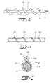
- Fig. 1 shows a screw 10 having a basic construction wherein a flexible rod comprises a metal rope 11, and a coating layer 12 of resin formed on the metal rope.
- a resin cord 13 is helically wound on the rod with a predetermined pitch.
- the screw measures 9 mm in the diameter of the rod, 3 mm in the diameter of the cord, 15 mm in the flight diameter thereof, and 35 mm in the cord winding pitch.
- Fig. 2 shows a screw 20 which comprises a rod 22 having a metal rope and a coating resin layer on the rope, and a resin code 23 wound around the rod and fitted in a helical groove 25 formed in the surface layer of the rod.
- FIG. 3 shows in section another screw 30 embodying the invention.
- a flexible rod 30a comprises a metal rope 31, and a coating layer 32 formed on the metal rope.
- a resin cord 30b helically wound on the rod 30a comprises a resin layer 34, and a core 33 in the form of a bundle of fibers having a specific amount of buckling of up to 3.0% in the center of the resin layer.
- Fig. 4 shows a screw comprising an integral molding of cord and rod. More specifically, a coating layer 42 applied on a metal rope 41 and a cord 43 having a rectangular cross section are molded integrally.
- Fig. 5 shows a screw 50 comprising a metal rope 51, a resin cord 53 wound on the rope, and a baked layer 52 covering the resulting assembly and prepared with a coating polymer composition, or a heat-shrinkable tube enclosing the assembly and shrunk by heating.
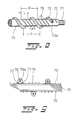
- Fig. 6 shows a screw wherein an abrasion-resistant tape is used
- Fig. 7 shows the same in longitudinal section.
- the screw 60 comprises a metal rope 61, and a coating layer formed on the metal rope 61 by helically winding a single-faced (or double-faced) adhesive tape 62 on the rope without any gap between the windings to cover the metal rope 61 with the tape 62.
- An abrasion-resistant resin tape 63 is further helically wound around the tape 62 in a direction opposite to the winding direction of the tape 62, with a helical gap 67 formed between the windings of the tape 63.
- a resin cord 64 is wound along the gap 67.
- the cord 64 has a core 64a centrally thereof and is fitted in the gap 67 between the windings of the tape 63 in contact with the tape 62 exposed at the gap 67.
- Fig. 8 shows a screw having metal wire windings.
- the screw 70 comprises a metal rope 71, a coating layer 72 covering the rope, a resin cord 73 having a core 73a and helically wound on the coating layer 72 with a specified pitch, and three metal wires 75 gap-wound at a predetermined distance from one another, around the coating layer in the helical gap defined by the windings of the cord 73.
- the center of windings width L of the metal wires 75 i.e., the metal wire positioned at the midpoint between the two other metal wires, is present in the center of the gap.
- Fig. 9 is a view in longitudinal section of another embodiment of screw 70' wherein metal wires are used.
- This embodiment comprises two metal wires 77 helically wound, with a gap formed therebetween, around a coated metal rope, a cord 73 wound on the rope in the gap between the windings of metal wire 77, and four metal wires 79 gap-wound on the rope in the helical gap between the windings of the cord.
- Fig. 10 is a plan view schematically showing the apparatus for illustrative purposes.
- the apparatus comprises the single screw and a guide which are arranged in parallel and spaced apart from each other by a distance for holding the necks of containers therebetween.
- the apparatus is of the one-side drive type wherein the screw is rotated to transport containers as held between the screw and the guide in suspension.
- such container transport apparatus are generally of the one-side drive type wherein a guide is opposed to the screw.
- two rails 101, 102 having an overall length of about 3 m are curved approximately through a right angle with a radius of curvature of 500 mm and arranged as opposed to each other.
- Permanent magnets 103 are embedded at a predetermined spacing (e.g., 200 mm) in the rails 101, 102.
- the screw 105 is held attracted to the rail 102 by the magnets 103 in the rail 102, and the guide 104' is secured to the rail 101.
- the screw 105 is rotatably supported at its one end by a bearing 107 and at the other end by another bearing 108.
- the guide 104' is immovably supported at its one end by a bearing 106 and at the other end thereof by the bearing 108.
- the bearing 108 is coupled to a motor 109, whereby the screw 105 is rotatable in the direction of arrow.
- the bearing 108 may have a speed change gear for adjusting the rotational speed to be transmitted to the screw 105.
- the containers (not shown in Fig. 10) held between the guide 104' and the screw 105 in suspension are moved in one direction (toward the bearing 108 in the drawing) by rotating the screw 105 in the direction of arrow.
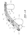
- Fig. 11 is a perspective view of Fig. 10 as partly omitted along the line A-A' therein
- Fig. 12 is a view in section taken along the line A-A'
- Fig. 13 is a diagram for illustrating the principle of transport by one-side drive.
- the rail 102 (the rail 101 is not shown in Fig. 11) has a rectangular body portion 121 of stainless steel and a shelf portion 122 projecting from the body portion 121 at a right angle therewith, and is L-shaped in its entirety.
- the rail 101 also has a body portion 111 and a shelf portion 112.
- Both the rails 101, 102 are supported at a given spacing by support arms 110 (not shown in Fig. 11 for the rail 101) with their shelf portions 112, 122 opposed to each other, and the support arms 110 are fixed to posts (not shown).
- the permanent magnets 103 which are rectangular, are embedded at the predetermined spacing in the body portions 111, 121.
- the guide 104' fixedly rests in a circular-arc groove 113 formed in the upper surface of the shelf portion 112.
- the screw 105 is fitted in a circular-arc groove 123 formed in the upper surface of the shelf portion 122 and is rotatable in sliding contact with the portion 122.
- the screw 105 is attracted to the side surface of the body portion 121 and held in engagement with the body portion 121 and the shelf portion 122 by the corresponding permanent magnets 103 so as not to be released from the rail 102. Consequently, the guide 104' and the screw 105 are easily removable from and mountable on the respective rails 101, 102 for the replacement of the guide and the screw.
- the guide 104' included in the present embodiment is in the form of a round bar of resin and is flexible.
- the round bar guide 104' which is placed on the rail 101, is merely secured to the rail 101 and is not rotatable.
- the screw 105 comprises a flexible rod 151, and a resin cord 152 helically wound on the rod with a specified pitch.
- the screw 105 is rotatable on the rail 102 by the motor 109 (see Fig. 10) in the direction of arrow.
- FIG. 12 showing the apparatus containers 200 made, for example, of polyethylene terephthalate are suspended by the guide 104' and the screw 105 as held therebetween, with a flange 201 on the neck of each container 200 in engagement with the guide 104' and the screw 105.
- the containers 200 With the rotation of the screw 105, the containers 200 are then transported in the direction of arrow a while rotating in the direction of arrow b each about its own axis.
- the containers 200 are advanced one after another by being pushed toward the direction of arrow a by the cord 152 of the screw 105.
- the present apparatus further has a system for removing reject containers while the containers are being transported in suspension. More specifically, a sensor 170 detects a damaged or cracked container, whereupon a drive mechanism 171 functions in response to a signal from the sensor 170, moving a portion of the guide 104', i.e., a shiftable portion 104a, toward the direction of arrow c . With the guide 104' thus locally removed, the reject container falls downward at this location. Upon the removal of the reject container, the shiftable portion 104a is immediately returned to the original position by the drive mechanism 171 so that the following containers can be transported free of trouble.
- the drive mechanism 171 may comprise a magnetic force generator for attracting the shiftable portion 104a when this portion 104a is made of a magnetic material, or may alternatively be a device for pulling the shiftable portion 104a.
- the mechanism is not limited insofar as the shiftable portion 104a is thereby movable in response to the detection signal from the sensor 170.
- Containers can be fed to the transport path by spacing the guide 104' and the screw 105 apart by an increased distance at the upstream end of the path as seen in Fig. 14.
- the guide 104' and the screw 105 are provided, each at one end thereof, with fasteners 145, 155, respectively, which are accommodated in the respective bearings 106, 107.
- the bearings 106, 107 are disposed away from each other.
- Each container is transferred to a position where the neck thereof is held between the guide 104' and the screw 105 by the engagement of its flange 201 therewith, by a conveyor or like feeder means (not shown) disposed below these members.
- the containers are readily feedable merely by bending the guide and the screw and thereby increasing the width of the transport path. This is attributable to the flexibility of the screw (and the guide) of the present invention and can in no way be realized with the use of the conventional rigid screw.
- the containers can be delivered from the apparatus selectively to the desired one of different positions utilizing the flexibility of the screw of the present invention, for example, by deflecting the other ends of the guide 104' and the screw 105 with the neck of the container held therebetween, by suitable delivery direction changing means (not shown) as shown in Fig. 15.
- FIG. 16 shows an apparatus wherein two screws are rotated by two-side drive.
- screws 104, 105 are held attracted to rails 101, 102, respectively.
- the screws 142, 152 comprise flexible rods 141, 151 and resin cords 104, 105, respectively, but are opposite to each other in the cord winding direction.
- containers 200 are transported in the direction of arrow a with the rotation of the two screws 104, 105.
- FIG. 17 shows an embodiment adapted to hold the trunks of containers.
- the container 200 is transported as placed on a conveyor 190 such as a chain conveyor or steel conveyor, and two pairs of screws 104, 105 for preventing the container from tumbling are arranged in opposed relation with each other at a spacing for holding the trunk at its upper and lower portions.
- the screws 104, 105 are respectively held attracted to rails 101, 102 having permanent magnets 103.
- Each rail is supported by support arms 110, which in turn are supported by posts 180, although the rails, support arms and posts for the upper screws 104, 105 are not shown in the drawing.
- the transport force for the containers is given by the conveyor 190, while the screws 104, 105 serve to support the trunk of each container at its opposite side. Transport of containers 200 can be expedited by rotating the screws 104, 105.
- Fig. 18 shows an arrangement wherein both the neck and the trunk of the container are held at the same time for transport.
- each of the neck and the trunk of the container 200 is held between a pair of screws 104, 105, and the container 200 is transported while being reliably held by the four screws.
- the container 200 can be rotated or positioned bottom up when a helical path of transport is installed, so that a process, for example, for washing or pasteurizing the interior of the container 200 can be readily incorporated into the transport path.
- Fig. 19 shows an embodiment for transporting a powder and granular material upward.
- the embodiment comprises a flexible pipe 310 providing a curved path of transport, and a flexible screw 300 having a flexible rod 301 and a resin cord 302 and extending through the pipe coaxially therewith.
- the screw 300 has one end connected directly to a motor 312 and the other end rotatably supported by a bearing (not shown).
- a motor 312 the other end rotatably supported by a bearing (not shown).
- Fig. 20 shows the assembly of screw and pipe during the transport of the powder and granular material 320.
- the material 320 present in the interior space of the pipe 310 around the screw 300 is pushed forward chiefly by the cord 302 owing to the rotation of the screw 300 in the direction of arrow and is continuously transported in the direction of arrow c .
Landscapes
- Engineering & Computer Science (AREA)
- Mechanical Engineering (AREA)
- Screw Conveyors (AREA)
Abstract
Applications Claiming Priority (27)
| Application Number | Priority Date | Filing Date | Title |
|---|---|---|---|
| JP27707489A JPH0829820B2 (ja) | 1989-10-26 | 1989-10-26 | スクリューコンベア |
| JP277074/89 | 1989-10-26 | ||
| JP2270990A JPH03227810A (ja) | 1990-02-01 | 1990-02-01 | コンベヤスクリュー |
| JP2271090A JPH03227811A (ja) | 1990-02-01 | 1990-02-01 | コンベヤスクリュー |
| JP2030503A JPH07115731B2 (ja) | 1990-02-09 | 1990-02-09 | 容器搬送装置用ガイドレール構造体 |
| JP3050290A JPH07115730B2 (ja) | 1990-02-09 | 1990-02-09 | 容器搬送装置用フレキシブルスクリュー |
| JP3050490A JPH03238217A (ja) | 1990-02-09 | 1990-02-09 | 容器搬送装置用ガイドレール構造体 |
| JP30502/90 | 1990-02-09 | ||
| JP2090138A JP2539695B2 (ja) | 1990-04-06 | 1990-04-06 | スクリュ―コンベア |
| JP90138/90 | 1990-04-06 | ||
| JP2113053A JP2816490B2 (ja) | 1990-04-28 | 1990-04-28 | 容器搬送装置用スクリュー |
| JP11305190A JPH0412920A (ja) | 1990-04-28 | 1990-04-28 | フレキシブルスクリュー |
| JP11305290A JPH0412921A (ja) | 1990-04-28 | 1990-04-28 | フレキシブルスクリュー |
| JP2113050A JP2818833B2 (ja) | 1990-04-28 | 1990-04-28 | 容器搬送装置 |
| JP112362/90 | 1990-04-30 | ||
| JP2112361A JPH0412917A (ja) | 1990-04-30 | 1990-04-30 | フレキシブルスクリュー |
| JP11235990A JPH0412915A (ja) | 1990-04-30 | 1990-04-30 | フレキシブルスクリュー |
| JP11236390A JPH0412919A (ja) | 1990-04-30 | 1990-04-30 | フレキシブルスクリュー |
| JP2191990A JPH0480112A (ja) | 1990-07-19 | 1990-07-19 | コンベヤ用フレキシブルシャフト |
| JP2191991A JPH0480113A (ja) | 1990-07-19 | 1990-07-19 | コンベヤ用フレキシブルシャフト |
| JP20548290A JPH0489705A (ja) | 1990-08-01 | 1990-08-01 | 金属線を螺旋状巻きしたコンベヤ用フレキシブルシャフト |
| JP205594/90 | 1990-08-02 | ||
| JP20559590A JPH0489707A (ja) | 1990-08-02 | 1990-08-02 | コンベヤ用フレキシブルシャフト |
| JP20559490A JP2852797B2 (ja) | 1990-08-02 | 1990-08-02 | 繊維束入りポリマー線材を有するコンベヤ用フレキシブルシャフト |
| PCT/JP1990/001379 WO1991006493A1 (fr) | 1989-10-26 | 1990-10-25 | Vis transporteuse flexible et appareil de transfert utilisant une telle vis |
| JP2112362A JP2802668B2 (ja) | 1990-04-30 | 1991-04-16 | フレキシブルスクリュー |
| JP11236090A JPH04319153A (ja) | 1990-04-30 | 1991-04-16 | パネル工法建物用パネルの枠組みフレームの組立連結構造 |
Publications (3)
| Publication Number | Publication Date |
|---|---|
| EP0450101A1 true EP0450101A1 (fr) | 1991-10-09 |
| EP0450101A4 EP0450101A4 (en) | 1992-04-08 |
| EP0450101B1 EP0450101B1 (fr) | 1994-12-28 |
Family
ID=27586496
Family Applications (1)
| Application Number | Title | Priority Date | Filing Date |
|---|---|---|---|
| EP90915819A Expired - Lifetime EP0450101B1 (fr) | 1989-10-26 | 1990-10-25 | Vis transporteuse flexible et appareil de transfert utilisant une telle vis |
Country Status (4)
| Country | Link |
|---|---|
| US (2) | US5295573A (fr) |
| EP (1) | EP0450101B1 (fr) |
| CA (1) | CA2044276A1 (fr) |
| WO (1) | WO1991006493A1 (fr) |
Cited By (6)
| Publication number | Priority date | Publication date | Assignee | Title |
|---|---|---|---|---|
| EP0560299A1 (fr) * | 1992-03-11 | 1993-09-15 | Mitsubishi Cable Industries, Ltd. | Vis transporteuse flexible |
| EP0571946A1 (fr) * | 1992-05-26 | 1993-12-01 | Mitsubishi Cable Industries, Ltd. | Système de transport à vis transporteuse flexible |
| WO1996014190A1 (fr) * | 1993-02-23 | 1996-05-17 | Cavendish Farms Limited | Appareil et procede destines a couper des spirales de pommes de terre |
| GB2308539A (en) * | 1994-11-03 | 1997-07-02 | Cavendish Farms Ltd | Apparatus and method for cutting helically shaped potato pieces |
| EP1256530A2 (fr) * | 2001-04-10 | 2002-11-13 | Bell & Howell Mail And Messaging Technologies Company | Méthode et dispositif de déchargement rapide de conteneurs et de transport de courrier |
| CN113560168A (zh) * | 2021-07-31 | 2021-10-29 | 苏州凯利洁环保科技有限公司 | 一种生活垃圾分级收集装置及收集系统 |
Families Citing this family (8)
| Publication number | Priority date | Publication date | Assignee | Title |
|---|---|---|---|---|
| EP1360369A1 (fr) * | 2001-02-15 | 2003-11-12 | N.V. Bekaert S.A. | Cordon metallique et etoffe comprenant ce cordon metallique |
| US7260924B2 (en) * | 2005-01-25 | 2007-08-28 | Voith Fabrics, Inc. | Seam pintle for paper making fabric |
| DE202006008659U1 (de) | 2006-05-30 | 2007-10-11 | Kuka Schweissanlagen Gmbh | Fördereinrichtung |
| US7690180B2 (en) * | 2007-09-18 | 2010-04-06 | Liberty Properties Management, Llc | Sewable fire resistant thread |
| US8490662B2 (en) * | 2009-01-08 | 2013-07-23 | Pouch Pac Innovations, Llc | Machine and method for manufacturing a packaged product |
| IT1395028B1 (it) * | 2009-08-06 | 2012-09-05 | Maccaferri Spa Off | Sistema e procedimento di addizione e dosaggio di fibre in una matrice cementizia |
| US9221592B2 (en) | 2012-11-02 | 2015-12-29 | Pouch Pac Innovations, Llc | Fitment for beverage pouch |
| CA2984818C (fr) * | 2016-11-18 | 2023-10-17 | Recover Energy Services Inc. | Transporteur a vis flexible |
Citations (6)
| Publication number | Priority date | Publication date | Assignee | Title |
|---|---|---|---|---|
| US3141545A (en) * | 1960-03-21 | 1964-07-21 | Cherry Burrell Corp | Conveyor structure |
| US3191762A (en) * | 1963-04-11 | 1965-06-29 | Northern Engraving And Mfg Com | Screw-type conveyor system |
| FR1434521A (fr) * | 1965-03-30 | 1966-04-08 | Rotorail | Transporteur du type à barre |
| GB2103171A (en) * | 1981-08-06 | 1983-02-16 | Jagenberg Werke Ag | Worm conveyor for objects such as shaped bottles |
| EP0187889A1 (fr) * | 1985-01-16 | 1986-07-23 | Industrie-Technik Erich A. Hindermann Aktiengesellschaft für Rationalisierung und Verfahrenstechnik | Dispositif pour vis transporteuses |
| DE8701229U1 (fr) * | 1987-01-12 | 1987-06-04 | Gummi-Jaeger Kg Gmbh & Cie, 3000 Hannover, De |
Family Cites Families (25)
| Publication number | Priority date | Publication date | Assignee | Title |
|---|---|---|---|---|
| US2620917A (en) * | 1949-02-28 | 1952-12-09 | Martin I Friedman | Garment handling means |
| DE1054013B (de) * | 1957-08-07 | 1959-03-26 | Werkzeugmaschinenfabrik Veb | Senkrechter Schneckenfoerderer |
| US3194385A (en) * | 1962-01-15 | 1965-07-13 | Barnese Anthony | Screw-type conveyor with resilient bearing means |
| DE1264326B (de) * | 1965-05-20 | 1968-03-21 | Blaise Rastoin | Schneckenfoerderer |
| US3360108A (en) * | 1966-08-29 | 1967-12-26 | Phillips Petroleum Co | Flexible conveying apparatus |
| ES353009A1 (es) * | 1967-04-22 | 1969-09-01 | Pirovano | Mejoras en la construccion de elementos transportadores pa-ra materiales sueltos, en polvo o en granulos, especialmentepiensos para pollos u otros animales. |
| GB1322803A (en) * | 1969-11-05 | 1973-07-11 | Rastoin B | Spiral-conveyor for pulverised granular fibrous or fluid product |
| US3727746A (en) * | 1970-10-22 | 1973-04-17 | Bank Of Higginsville | Flexible auger |
| US3967722A (en) * | 1972-06-08 | 1976-07-06 | Harry W. Dietert Co. | Sample feed auger structure |
| JPS50102841A (fr) * | 1974-01-17 | 1975-08-14 | ||
| JPS5216203Y2 (fr) * | 1974-02-01 | 1977-04-12 | ||
| GB1585440A (en) * | 1977-05-24 | 1981-03-04 | Eriksson K | Apparatus for feeding ojects from a conveyor |
| JPS5434978U (fr) * | 1977-08-12 | 1979-03-07 | ||
| JPS5434978A (en) * | 1977-08-22 | 1979-03-14 | Kawai Electric Heater | Heater for such as coffee maker |
| DE3006101A1 (de) * | 1980-02-19 | 1981-08-27 | Metallgesellschaft Ag, 6000 Frankfurt | Werkstuecke mit gepanzerten kanten und/oder flaechen |
| JPS5811769Y2 (ja) * | 1980-03-04 | 1983-03-05 | 松本 富夫 | フレキシブルスクリユ−コンベア |
| JPS56132220A (en) * | 1980-03-14 | 1981-10-16 | Daifuku Co Ltd | Conveyance system |
| US4301912A (en) * | 1980-03-21 | 1981-11-24 | The Mead Corporation | Divider screws |
| JPS57188713A (en) * | 1981-05-15 | 1982-11-19 | Yamaha Motor Co Ltd | Assembling type valve cam shaft |
| JPH0126651Y2 (fr) * | 1981-05-28 | 1989-08-09 | ||
| JPS5962430A (ja) * | 1982-09-30 | 1984-04-09 | 大阪シ−リング印刷株式会社 | ラベル貼付用搬送装置 |
| JPS60187113A (ja) * | 1984-03-07 | 1985-09-24 | Marantz Japan Inc | 音響装置等に用いられるチユ−ナの遠隔コントロ−ル装置 |
| JPS60187113U (ja) * | 1984-05-21 | 1985-12-11 | 株式会社明電舎 | 同期移送用タイミングスクリユ−の制御装置 |
| JPS6151411A (ja) * | 1984-08-18 | 1986-03-13 | Canon Inc | 粉体搬送用パイプ |
| JP2500943B2 (ja) * | 1990-12-19 | 1996-05-29 | 三菱電機株式会社 | 電流検出装置 |
-
1990
- 1990-10-25 WO PCT/JP1990/001379 patent/WO1991006493A1/fr active IP Right Grant
- 1990-10-25 EP EP90915819A patent/EP0450101B1/fr not_active Expired - Lifetime
- 1990-10-25 CA CA002044276A patent/CA2044276A1/fr not_active Abandoned
-
1991
- 1991-06-16 US US07/720,484 patent/US5295573A/en not_active Expired - Fee Related
-
1993
- 1993-12-30 US US08/176,115 patent/US5396981A/en not_active Expired - Fee Related
Patent Citations (6)
| Publication number | Priority date | Publication date | Assignee | Title |
|---|---|---|---|---|
| US3141545A (en) * | 1960-03-21 | 1964-07-21 | Cherry Burrell Corp | Conveyor structure |
| US3191762A (en) * | 1963-04-11 | 1965-06-29 | Northern Engraving And Mfg Com | Screw-type conveyor system |
| FR1434521A (fr) * | 1965-03-30 | 1966-04-08 | Rotorail | Transporteur du type à barre |
| GB2103171A (en) * | 1981-08-06 | 1983-02-16 | Jagenberg Werke Ag | Worm conveyor for objects such as shaped bottles |
| EP0187889A1 (fr) * | 1985-01-16 | 1986-07-23 | Industrie-Technik Erich A. Hindermann Aktiengesellschaft für Rationalisierung und Verfahrenstechnik | Dispositif pour vis transporteuses |
| DE8701229U1 (fr) * | 1987-01-12 | 1987-06-04 | Gummi-Jaeger Kg Gmbh & Cie, 3000 Hannover, De |
Non-Patent Citations (1)
| Title |
|---|
| See also references of WO9106493A1 * |
Cited By (8)
| Publication number | Priority date | Publication date | Assignee | Title |
|---|---|---|---|---|
| EP0560299A1 (fr) * | 1992-03-11 | 1993-09-15 | Mitsubishi Cable Industries, Ltd. | Vis transporteuse flexible |
| EP0571946A1 (fr) * | 1992-05-26 | 1993-12-01 | Mitsubishi Cable Industries, Ltd. | Système de transport à vis transporteuse flexible |
| WO1996014190A1 (fr) * | 1993-02-23 | 1996-05-17 | Cavendish Farms Limited | Appareil et procede destines a couper des spirales de pommes de terre |
| GB2308539A (en) * | 1994-11-03 | 1997-07-02 | Cavendish Farms Ltd | Apparatus and method for cutting helically shaped potato pieces |
| GB2308539B (en) * | 1994-11-03 | 1998-11-18 | Cavendish Farms Ltd | Apparatus and method for cutting helically shaped potato pieces |
| EP1256530A2 (fr) * | 2001-04-10 | 2002-11-13 | Bell & Howell Mail And Messaging Technologies Company | Méthode et dispositif de déchargement rapide de conteneurs et de transport de courrier |
| CN113560168A (zh) * | 2021-07-31 | 2021-10-29 | 苏州凯利洁环保科技有限公司 | 一种生活垃圾分级收集装置及收集系统 |
| CN113560168B (zh) * | 2021-07-31 | 2022-08-05 | 苏州凯利洁环保科技有限公司 | 一种生活垃圾分级收集装置及收集系统 |
Also Published As
| Publication number | Publication date |
|---|---|
| CA2044276A1 (fr) | 1991-04-27 |
| EP0450101B1 (fr) | 1994-12-28 |
| EP0450101A4 (en) | 1992-04-08 |
| WO1991006493A1 (fr) | 1991-05-16 |
| US5396981A (en) | 1995-03-14 |
| US5295573A (en) | 1994-03-22 |
Similar Documents
| Publication | Publication Date | Title |
|---|---|---|
| EP0450101B1 (fr) | Vis transporteuse flexible et appareil de transfert utilisant une telle vis | |
| EP0334359B1 (fr) | Procédé et dispositif pour introduire des corps fibreux dans des tubes | |
| EP0560299B1 (fr) | Vis transporteuse flexible | |
| US5303814A (en) | Flexible screw type conveyor system | |
| EP2917137B1 (fr) | Fil de transport et procédé pour sa production | |
| JPH0640540A (ja) | フレキシブルスクリュー搬送装置 | |
| JP2681238B2 (ja) | 繊維束入りポリマー線材を有するコンベヤ用フレキシブルスクリュー | |
| JPH0489705A (ja) | 金属線を螺旋状巻きしたコンベヤ用フレキシブルシャフト | |
| JP2642467B2 (ja) | 管内への線状体挿通方法 | |
| JPH0489707A (ja) | コンベヤ用フレキシブルシャフト | |
| JPH0480112A (ja) | コンベヤ用フレキシブルシャフト | |
| JPH0480113A (ja) | コンベヤ用フレキシブルシャフト | |
| JP2852797B2 (ja) | 繊維束入りポリマー線材を有するコンベヤ用フレキシブルシャフト | |
| JP2852793B2 (ja) | コンベヤ用フレキシブルシャフトの製法 | |
| JP2802668B2 (ja) | フレキシブルスクリュー | |
| JPH0412920A (ja) | フレキシブルスクリュー | |
| JPH05254632A (ja) | コンベヤ用フレキシブルスクリュー | |
| JPH06263229A (ja) | 円板状体の搬送装置 | |
| JPH05254629A (ja) | フレキシブルスクリューの使用方法 | |
| JP3025371B2 (ja) | フレキシブルスクリュー | |
| JP2554699B2 (ja) | 管内への線状体挿通方法 | |
| JPH06263228A (ja) | コインまたはメダルの搬送装置 | |
| JPH0480111A (ja) | コンベヤ用フレキシブルシャフト及びその製法 | |
| JPH0769500B2 (ja) | 管内への線状体挿通方法 | |
| KR900006507B1 (ko) | 관내로 광섬유를 통과시키는 방법 및 그 장치 |
Legal Events
| Date | Code | Title | Description |
|---|---|---|---|
| PUAI | Public reference made under article 153(3) epc to a published international application that has entered the european phase |
Free format text: ORIGINAL CODE: 0009012 |
|
| AK | Designated contracting states |
Kind code of ref document: A1 Designated state(s): DE FR GB |
|
| 17P | Request for examination filed |
Effective date: 19910919 |
|
| A4 | Supplementary search report drawn up and despatched |
Effective date: 19920218 |
|
| AK | Designated contracting states |
Kind code of ref document: A4 Designated state(s): DE FR GB |
|
| 17Q | First examination report despatched |
Effective date: 19930625 |
|
| GRAA | (expected) grant |
Free format text: ORIGINAL CODE: 0009210 |
|
| AK | Designated contracting states |
Kind code of ref document: B1 Designated state(s): DE FR GB |
|
| REF | Corresponds to: |
Ref document number: 69015615 Country of ref document: DE Date of ref document: 19950209 |
|
| ET | Fr: translation filed | ||
| PLBE | No opposition filed within time limit |
Free format text: ORIGINAL CODE: 0009261 |
|
| STAA | Information on the status of an ep patent application or granted ep patent |
Free format text: STATUS: NO OPPOSITION FILED WITHIN TIME LIMIT |
|
| 26N | No opposition filed | ||
| PGFP | Annual fee paid to national office [announced via postgrant information from national office to epo] |
Ref country code: FR Payment date: 19981009 Year of fee payment: 9 |
|
| PGFP | Annual fee paid to national office [announced via postgrant information from national office to epo] |
Ref country code: GB Payment date: 19981030 Year of fee payment: 9 |
|
| PGFP | Annual fee paid to national office [announced via postgrant information from national office to epo] |
Ref country code: DE Payment date: 19981103 Year of fee payment: 9 |
|
| PG25 | Lapsed in a contracting state [announced via postgrant information from national office to epo] |
Ref country code: GB Free format text: LAPSE BECAUSE OF NON-PAYMENT OF DUE FEES Effective date: 19991025 |
|
| GBPC | Gb: european patent ceased through non-payment of renewal fee |
Effective date: 19991025 |
|
| PG25 | Lapsed in a contracting state [announced via postgrant information from national office to epo] |
Ref country code: FR Free format text: LAPSE BECAUSE OF NON-PAYMENT OF DUE FEES Effective date: 20000630 |
|
| PG25 | Lapsed in a contracting state [announced via postgrant information from national office to epo] |
Ref country code: DE Free format text: LAPSE BECAUSE OF NON-PAYMENT OF DUE FEES Effective date: 20000801 |
|
| REG | Reference to a national code |
Ref country code: FR Ref legal event code: ST |