EP0447588B1 - Flüssigkeitsstrahlaufzeichnungskopf und Aufzeichnungsgerät, versehen mit diesem Kopf - Google Patents
Flüssigkeitsstrahlaufzeichnungskopf und Aufzeichnungsgerät, versehen mit diesem Kopf Download PDFInfo
- Publication number
- EP0447588B1 EP0447588B1 EP90105465A EP90105465A EP0447588B1 EP 0447588 B1 EP0447588 B1 EP 0447588B1 EP 90105465 A EP90105465 A EP 90105465A EP 90105465 A EP90105465 A EP 90105465A EP 0447588 B1 EP0447588 B1 EP 0447588B1
- Authority
- EP
- European Patent Office
- Prior art keywords
- group
- methacrylate
- recording head
- monomer
- liquid
- Prior art date
- Legal status (The legal status is an assumption and is not a legal conclusion. Google has not performed a legal analysis and makes no representation as to the accuracy of the status listed.)
- Expired - Lifetime
Links
- 239000007788 liquid Substances 0.000 title claims abstract description 172
- 239000000178 monomer Substances 0.000 claims abstract description 95
- 239000011342 resin composition Substances 0.000 claims abstract description 58
- 229920000642 polymer Polymers 0.000 claims abstract description 50
- -1 alkyl methacrylates Chemical class 0.000 claims abstract description 39
- 239000000203 mixture Substances 0.000 claims abstract description 28
- 125000004432 carbon atom Chemical group C* 0.000 claims abstract description 26
- PPBRXRYQALVLMV-UHFFFAOYSA-N Styrene Chemical compound C=CC1=CC=CC=C1 PPBRXRYQALVLMV-UHFFFAOYSA-N 0.000 claims abstract description 22
- 125000004435 hydrogen atom Chemical group [H]* 0.000 claims abstract description 22
- 125000000217 alkyl group Chemical group 0.000 claims abstract description 17
- 239000003999 initiator Substances 0.000 claims abstract description 14
- 125000002887 hydroxy group Chemical group [H]O* 0.000 claims abstract description 11
- NLHHRLWOUZZQLW-UHFFFAOYSA-N Acrylonitrile Chemical compound C=CC#N NLHHRLWOUZZQLW-UHFFFAOYSA-N 0.000 claims abstract description 10
- CERQOIWHTDAKMF-UHFFFAOYSA-M Methacrylate Chemical compound CC(=C)C([O-])=O CERQOIWHTDAKMF-UHFFFAOYSA-M 0.000 claims abstract description 10
- VVQNEPGJFQJSBK-UHFFFAOYSA-N Methyl methacrylate Chemical compound COC(=O)C(C)=C VVQNEPGJFQJSBK-UHFFFAOYSA-N 0.000 claims abstract description 8
- 125000003647 acryloyl group Chemical group O=C([*])C([H])=C([H])[H] 0.000 claims abstract description 8
- 230000009477 glass transition Effects 0.000 claims abstract description 8
- OIWOHHBRDFKZNC-UHFFFAOYSA-N cyclohexyl 2-methylprop-2-enoate Chemical compound CC(=C)C(=O)OC1CCCCC1 OIWOHHBRDFKZNC-UHFFFAOYSA-N 0.000 claims abstract description 6
- SUPCQIBBMFXVTL-UHFFFAOYSA-N ethyl 2-methylprop-2-enoate Chemical compound CCOC(=O)C(C)=C SUPCQIBBMFXVTL-UHFFFAOYSA-N 0.000 claims abstract description 6
- 125000002496 methyl group Chemical group [H]C([H])([H])* 0.000 claims abstract description 6
- PSGCQDPCAWOCSH-UHFFFAOYSA-N (4,7,7-trimethyl-3-bicyclo[2.2.1]heptanyl) prop-2-enoate Chemical compound C1CC2(C)C(OC(=O)C=C)CC1C2(C)C PSGCQDPCAWOCSH-UHFFFAOYSA-N 0.000 claims abstract description 5
- JKNCOURZONDCGV-UHFFFAOYSA-N 2-(dimethylamino)ethyl 2-methylprop-2-enoate Chemical compound CN(C)CCOC(=O)C(C)=C JKNCOURZONDCGV-UHFFFAOYSA-N 0.000 claims abstract description 5
- RUMACXVDVNRZJZ-UHFFFAOYSA-N 2-methylpropyl 2-methylprop-2-enoate Chemical compound CC(C)COC(=O)C(C)=C RUMACXVDVNRZJZ-UHFFFAOYSA-N 0.000 claims abstract description 5
- IAXXETNIOYFMLW-COPLHBTASA-N [(1s,3s,4s)-4,7,7-trimethyl-3-bicyclo[2.2.1]heptanyl] 2-methylprop-2-enoate Chemical compound C1C[C@]2(C)[C@@H](OC(=O)C(=C)C)C[C@H]1C2(C)C IAXXETNIOYFMLW-COPLHBTASA-N 0.000 claims abstract description 5
- 125000005011 alkyl ether group Chemical group 0.000 claims abstract description 5
- AOJOEFVRHOZDFN-UHFFFAOYSA-N benzyl 2-methylprop-2-enoate Chemical compound CC(=C)C(=O)OCC1=CC=CC=C1 AOJOEFVRHOZDFN-UHFFFAOYSA-N 0.000 claims abstract description 5
- 125000002768 hydroxyalkyl group Chemical group 0.000 claims abstract description 5
- 229940119545 isobornyl methacrylate Drugs 0.000 claims abstract description 5
- SJMYWORNLPSJQO-UHFFFAOYSA-N tert-butyl 2-methylprop-2-enoate Chemical compound CC(=C)C(=O)OC(C)(C)C SJMYWORNLPSJQO-UHFFFAOYSA-N 0.000 claims abstract description 5
- 238000007599 discharging Methods 0.000 claims description 28
- 239000012790 adhesive layer Substances 0.000 claims description 7
- 125000002947 alkylene group Chemical group 0.000 claims description 7
- 239000010408 film Substances 0.000 description 105
- 239000000758 substrate Substances 0.000 description 55
- 238000000034 method Methods 0.000 description 44
- 229920005989 resin Polymers 0.000 description 31
- 239000011347 resin Substances 0.000 description 31
- 238000001723 curing Methods 0.000 description 29
- 239000011248 coating agent Substances 0.000 description 23
- 238000000576 coating method Methods 0.000 description 23
- 239000010410 layer Substances 0.000 description 22
- 230000015572 biosynthetic process Effects 0.000 description 16
- 239000000463 material Substances 0.000 description 16
- 239000000047 product Substances 0.000 description 15
- 239000011521 glass Substances 0.000 description 13
- 239000002904 solvent Substances 0.000 description 13
- MTHSVFCYNBDYFN-UHFFFAOYSA-N diethylene glycol Chemical compound OCCOCCO MTHSVFCYNBDYFN-UHFFFAOYSA-N 0.000 description 12
- QSHDDOUJBYECFT-UHFFFAOYSA-N mercury Chemical compound [Hg] QSHDDOUJBYECFT-UHFFFAOYSA-N 0.000 description 10
- 229910052753 mercury Inorganic materials 0.000 description 10
- 239000000126 substance Substances 0.000 description 10
- NIXOWILDQLNWCW-UHFFFAOYSA-M Acrylate Chemical compound [O-]C(=O)C=C NIXOWILDQLNWCW-UHFFFAOYSA-M 0.000 description 9
- 229910052751 metal Inorganic materials 0.000 description 9
- 239000002184 metal Substances 0.000 description 9
- NIXOWILDQLNWCW-UHFFFAOYSA-N 2-Propenoic acid Natural products OC(=O)C=C NIXOWILDQLNWCW-UHFFFAOYSA-N 0.000 description 8
- 239000000919 ceramic Substances 0.000 description 8
- 230000008859 change Effects 0.000 description 8
- 239000000470 constituent Substances 0.000 description 8
- SMZOUWXMTYCWNB-UHFFFAOYSA-N 2-(2-methoxy-5-methylphenyl)ethanamine Chemical compound COC1=CC=C(C)C=C1CCN SMZOUWXMTYCWNB-UHFFFAOYSA-N 0.000 description 7
- LYCAIKOWRPUZTN-UHFFFAOYSA-N Ethylene glycol Chemical compound OCCO LYCAIKOWRPUZTN-UHFFFAOYSA-N 0.000 description 7
- CERQOIWHTDAKMF-UHFFFAOYSA-N Methacrylic acid Chemical compound CC(=C)C(O)=O CERQOIWHTDAKMF-UHFFFAOYSA-N 0.000 description 7
- 239000000853 adhesive Substances 0.000 description 7
- 230000001070 adhesive effect Effects 0.000 description 7
- 238000002360 preparation method Methods 0.000 description 7
- ZWEHNKRNPOVVGH-UHFFFAOYSA-N 2-Butanone Chemical compound CCC(C)=O ZWEHNKRNPOVVGH-UHFFFAOYSA-N 0.000 description 6
- VYPSYNLAJGMNEJ-UHFFFAOYSA-N Silicium dioxide Chemical compound O=[Si]=O VYPSYNLAJGMNEJ-UHFFFAOYSA-N 0.000 description 6
- 239000000654 additive Substances 0.000 description 6
- 150000001875 compounds Chemical class 0.000 description 6
- 229920003023 plastic Polymers 0.000 description 6
- 239000004033 plastic Substances 0.000 description 6
- 238000007639 printing Methods 0.000 description 6
- 230000007261 regionalization Effects 0.000 description 6
- 230000035945 sensitivity Effects 0.000 description 6
- 238000003786 synthesis reaction Methods 0.000 description 6
- UOCLXMDMGBRAIB-UHFFFAOYSA-N 1,1,1-trichloroethane Chemical compound CC(Cl)(Cl)Cl UOCLXMDMGBRAIB-UHFFFAOYSA-N 0.000 description 5
- 239000004698 Polyethylene Substances 0.000 description 5
- 239000002202 Polyethylene glycol Substances 0.000 description 5
- 230000000996 additive effect Effects 0.000 description 5
- 238000001704 evaporation Methods 0.000 description 5
- 230000008020 evaporation Effects 0.000 description 5
- 238000010438 heat treatment Methods 0.000 description 5
- 238000000059 patterning Methods 0.000 description 5
- 229920000573 polyethylene Polymers 0.000 description 5
- 229920001223 polyethylene glycol Polymers 0.000 description 5
- 229920000139 polyethylene terephthalate Polymers 0.000 description 5
- 239000005020 polyethylene terephthalate Substances 0.000 description 5
- 238000006116 polymerization reaction Methods 0.000 description 5
- 238000012545 processing Methods 0.000 description 5
- RTZKZFJDLAIYFH-UHFFFAOYSA-N Diethyl ether Chemical compound CCOCC RTZKZFJDLAIYFH-UHFFFAOYSA-N 0.000 description 4
- QIGBRXMKCJKVMJ-UHFFFAOYSA-N Hydroquinone Chemical compound OC1=CC=C(O)C=C1 QIGBRXMKCJKVMJ-UHFFFAOYSA-N 0.000 description 4
- WOBHKFSMXKNTIM-UHFFFAOYSA-N Hydroxyethyl methacrylate Chemical compound CC(=C)C(=O)OCCO WOBHKFSMXKNTIM-UHFFFAOYSA-N 0.000 description 4
- SECXISVLQFMRJM-UHFFFAOYSA-N N-Methylpyrrolidone Chemical compound CN1CCCC1=O SECXISVLQFMRJM-UHFFFAOYSA-N 0.000 description 4
- 239000012965 benzophenone Substances 0.000 description 4
- 238000013461 design Methods 0.000 description 4
- 238000007598 dipping method Methods 0.000 description 4
- 230000000694 effects Effects 0.000 description 4
- 238000010894 electron beam technology Methods 0.000 description 4
- 150000002148 esters Chemical class 0.000 description 4
- 239000000049 pigment Substances 0.000 description 4
- 239000011241 protective layer Substances 0.000 description 4
- 150000003254 radicals Chemical class 0.000 description 4
- 239000007787 solid Substances 0.000 description 4
- 238000012360 testing method Methods 0.000 description 4
- YMWUJEATGCHHMB-UHFFFAOYSA-N Dichloromethane Chemical compound ClCCl YMWUJEATGCHHMB-UHFFFAOYSA-N 0.000 description 3
- 239000004593 Epoxy Substances 0.000 description 3
- XEKOWRVHYACXOJ-UHFFFAOYSA-N Ethyl acetate Chemical compound CCOC(C)=O XEKOWRVHYACXOJ-UHFFFAOYSA-N 0.000 description 3
- HEMHJVSKTPXQMS-UHFFFAOYSA-M Sodium hydroxide Chemical compound [OH-].[Na+] HEMHJVSKTPXQMS-UHFFFAOYSA-M 0.000 description 3
- YXFVVABEGXRONW-UHFFFAOYSA-N Toluene Chemical compound CC1=CC=CC=C1 YXFVVABEGXRONW-UHFFFAOYSA-N 0.000 description 3
- 125000005396 acrylic acid ester group Chemical group 0.000 description 3
- 230000008901 benefit Effects 0.000 description 3
- RWCCWEUUXYIKHB-UHFFFAOYSA-N benzophenone Chemical compound C=1C=CC=CC=1C(=O)C1=CC=CC=C1 RWCCWEUUXYIKHB-UHFFFAOYSA-N 0.000 description 3
- 239000007795 chemical reaction product Substances 0.000 description 3
- 238000005520 cutting process Methods 0.000 description 3
- 238000010586 diagram Methods 0.000 description 3
- 239000000975 dye Substances 0.000 description 3
- 230000006872 improvement Effects 0.000 description 3
- 238000005259 measurement Methods 0.000 description 3
- 229910001507 metal halide Inorganic materials 0.000 description 3
- 150000005309 metal halides Chemical class 0.000 description 3
- 125000005397 methacrylic acid ester group Chemical group 0.000 description 3
- 238000002156 mixing Methods 0.000 description 3
- 230000035515 penetration Effects 0.000 description 3
- 229920000728 polyester Polymers 0.000 description 3
- 239000005056 polyisocyanate Substances 0.000 description 3
- 229920001228 polyisocyanate Polymers 0.000 description 3
- 229920001451 polypropylene glycol Polymers 0.000 description 3
- 230000002035 prolonged effect Effects 0.000 description 3
- 239000000377 silicon dioxide Substances 0.000 description 3
- 238000012719 thermal polymerization Methods 0.000 description 3
- 229920002818 (Hydroxyethyl)methacrylate Polymers 0.000 description 2
- 0 *C(*)(C(CC1O*N(*)N=N)*2)[C@]1C2N Chemical compound *C(*)(C(CC1O*N(*)N=N)*2)[C@]1C2N 0.000 description 2
- OZAIFHULBGXAKX-UHFFFAOYSA-N 2-(2-cyanopropan-2-yldiazenyl)-2-methylpropanenitrile Chemical compound N#CC(C)(C)N=NC(C)(C)C#N OZAIFHULBGXAKX-UHFFFAOYSA-N 0.000 description 2
- HZAXFHJVJLSVMW-UHFFFAOYSA-N 2-Aminoethan-1-ol Chemical compound NCCO HZAXFHJVJLSVMW-UHFFFAOYSA-N 0.000 description 2
- OMIGHNLMNHATMP-UHFFFAOYSA-N 2-hydroxyethyl prop-2-enoate Chemical compound OCCOC(=O)C=C OMIGHNLMNHATMP-UHFFFAOYSA-N 0.000 description 2
- QZPSOSOOLFHYRR-UHFFFAOYSA-N 3-hydroxypropyl prop-2-enoate Chemical compound OCCCOC(=O)C=C QZPSOSOOLFHYRR-UHFFFAOYSA-N 0.000 description 2
- VVBLNCFGVYUYGU-UHFFFAOYSA-N 4,4'-Bis(dimethylamino)benzophenone Chemical compound C1=CC(N(C)C)=CC=C1C(=O)C1=CC=C(N(C)C)C=C1 VVBLNCFGVYUYGU-UHFFFAOYSA-N 0.000 description 2
- KWOLFJPFCHCOCG-UHFFFAOYSA-N Acetophenone Chemical compound CC(=O)C1=CC=CC=C1 KWOLFJPFCHCOCG-UHFFFAOYSA-N 0.000 description 2
- SOGAXMICEFXMKE-UHFFFAOYSA-N Butylmethacrylate Chemical compound CCCCOC(=O)C(C)=C SOGAXMICEFXMKE-UHFFFAOYSA-N 0.000 description 2
- JOYRKODLDBILNP-UHFFFAOYSA-N Ethyl urethane Chemical compound CCOC(N)=O JOYRKODLDBILNP-UHFFFAOYSA-N 0.000 description 2
- 239000004606 Fillers/Extenders Substances 0.000 description 2
- BAPJBEWLBFYGME-UHFFFAOYSA-N Methyl acrylate Chemical compound COC(=O)C=C BAPJBEWLBFYGME-UHFFFAOYSA-N 0.000 description 2
- CNCOEDDPFOAUMB-UHFFFAOYSA-N N-Methylolacrylamide Chemical compound OCNC(=O)C=C CNCOEDDPFOAUMB-UHFFFAOYSA-N 0.000 description 2
- 238000002835 absorbance Methods 0.000 description 2
- 150000001252 acrylic acid derivatives Chemical class 0.000 description 2
- 229920006243 acrylic copolymer Polymers 0.000 description 2
- IISBACLAFKSPIT-UHFFFAOYSA-N bisphenol A Chemical compound C=1C=C(O)C=CC=1C(C)(C)C1=CC=C(O)C=C1 IISBACLAFKSPIT-UHFFFAOYSA-N 0.000 description 2
- PXKLMJQFEQBVLD-UHFFFAOYSA-N bisphenol F Chemical compound C1=CC(O)=CC=C1CC1=CC=C(O)C=C1 PXKLMJQFEQBVLD-UHFFFAOYSA-N 0.000 description 2
- 125000003178 carboxy group Chemical group [H]OC(*)=O 0.000 description 2
- 239000003054 catalyst Substances 0.000 description 2
- 239000003795 chemical substances by application Substances 0.000 description 2
- 239000011247 coating layer Substances 0.000 description 2
- 229910052681 coesite Inorganic materials 0.000 description 2
- 239000003086 colorant Substances 0.000 description 2
- 238000009833 condensation Methods 0.000 description 2
- 230000005494 condensation Effects 0.000 description 2
- 229910052906 cristobalite Inorganic materials 0.000 description 2
- 238000004132 cross linking Methods 0.000 description 2
- 238000004090 dissolution Methods 0.000 description 2
- 229920001971 elastomer Polymers 0.000 description 2
- 239000003822 epoxy resin Substances 0.000 description 2
- 238000005530 etching Methods 0.000 description 2
- 125000003055 glycidyl group Chemical group C(C1CO1)* 0.000 description 2
- 229920000578 graft copolymer Polymers 0.000 description 2
- RRAMGCGOFNQTLD-UHFFFAOYSA-N hexamethylene diisocyanate Chemical compound O=C=NCCCCCCN=C=O RRAMGCGOFNQTLD-UHFFFAOYSA-N 0.000 description 2
- 239000004615 ingredient Substances 0.000 description 2
- 239000003112 inhibitor Substances 0.000 description 2
- ZFSLODLOARCGLH-UHFFFAOYSA-N isocyanuric acid Chemical compound OC1=NC(O)=NC(O)=N1 ZFSLODLOARCGLH-UHFFFAOYSA-N 0.000 description 2
- BDAGIHXWWSANSR-UHFFFAOYSA-N methanoic acid Natural products OC=O BDAGIHXWWSANSR-UHFFFAOYSA-N 0.000 description 2
- 238000012986 modification Methods 0.000 description 2
- 239000003960 organic solvent Substances 0.000 description 2
- 230000003647 oxidation Effects 0.000 description 2
- 238000007254 oxidation reaction Methods 0.000 description 2
- NWVVVBRKAWDGAB-UHFFFAOYSA-N p-methoxyphenol Chemical compound COC1=CC=C(O)C=C1 NWVVVBRKAWDGAB-UHFFFAOYSA-N 0.000 description 2
- 239000003973 paint Substances 0.000 description 2
- 239000002985 plastic film Substances 0.000 description 2
- 229920006255 plastic film Polymers 0.000 description 2
- 229920000647 polyepoxide Polymers 0.000 description 2
- 230000002441 reversible effect Effects 0.000 description 2
- 239000005060 rubber Substances 0.000 description 2
- 230000035939 shock Effects 0.000 description 2
- 235000012239 silicon dioxide Nutrition 0.000 description 2
- 229910052682 stishovite Inorganic materials 0.000 description 2
- 230000008961 swelling Effects 0.000 description 2
- DVKJHBMWWAPEIU-UHFFFAOYSA-N toluene 2,4-diisocyanate Chemical compound CC1=CC=C(N=C=O)C=C1N=C=O DVKJHBMWWAPEIU-UHFFFAOYSA-N 0.000 description 2
- JOXIMZWYDAKGHI-UHFFFAOYSA-N toluene-4-sulfonic acid Chemical compound CC1=CC=C(S(O)(=O)=O)C=C1 JOXIMZWYDAKGHI-UHFFFAOYSA-N 0.000 description 2
- 229910052905 tridymite Inorganic materials 0.000 description 2
- MSAHTMIQULFMRG-UHFFFAOYSA-N 1,2-diphenyl-2-propan-2-yloxyethanone Chemical compound C=1C=CC=CC=1C(OC(C)C)C(=O)C1=CC=CC=C1 MSAHTMIQULFMRG-UHFFFAOYSA-N 0.000 description 1
- CYSGHNMQYZDMIA-UHFFFAOYSA-N 1,3-Dimethyl-2-imidazolidinon Chemical compound CN1CCN(C)C1=O CYSGHNMQYZDMIA-UHFFFAOYSA-N 0.000 description 1
- DKEGCUDAFWNSSO-UHFFFAOYSA-N 1,8-dibromooctane Chemical compound BrCCCCCCCCBr DKEGCUDAFWNSSO-UHFFFAOYSA-N 0.000 description 1
- IMDHDEPPVWETOI-UHFFFAOYSA-N 1-(4-tert-butylphenyl)-2,2,2-trichloroethanone Chemical compound CC(C)(C)C1=CC=C(C(=O)C(Cl)(Cl)Cl)C=C1 IMDHDEPPVWETOI-UHFFFAOYSA-N 0.000 description 1
- VMCRQYHCDSXNLW-UHFFFAOYSA-N 1-(4-tert-butylphenyl)-2,2-dichloroethanone Chemical compound CC(C)(C)C1=CC=C(C(=O)C(Cl)Cl)C=C1 VMCRQYHCDSXNLW-UHFFFAOYSA-N 0.000 description 1
- OZCMOJQQLBXBKI-UHFFFAOYSA-N 1-ethenoxy-2-methylpropane Chemical compound CC(C)COC=C OZCMOJQQLBXBKI-UHFFFAOYSA-N 0.000 description 1
- WJFKNYWRSNBZNX-UHFFFAOYSA-N 10H-phenothiazine Chemical compound C1=CC=C2NC3=CC=CC=C3SC2=C1 WJFKNYWRSNBZNX-UHFFFAOYSA-N 0.000 description 1
- PIZHFBODNLEQBL-UHFFFAOYSA-N 2,2-diethoxy-1-phenylethanone Chemical compound CCOC(OCC)C(=O)C1=CC=CC=C1 PIZHFBODNLEQBL-UHFFFAOYSA-N 0.000 description 1
- KWVGIHKZDCUPEU-UHFFFAOYSA-N 2,2-dimethoxy-2-phenylacetophenone Chemical compound C=1C=CC=CC=1C(OC)(OC)C(=O)C1=CC=CC=C1 KWVGIHKZDCUPEU-UHFFFAOYSA-N 0.000 description 1
- BRKORVYTKKLNKX-UHFFFAOYSA-N 2,4-di(propan-2-yl)thioxanthen-9-one Chemical compound C1=CC=C2C(=O)C3=CC(C(C)C)=CC(C(C)C)=C3SC2=C1 BRKORVYTKKLNKX-UHFFFAOYSA-N 0.000 description 1
- LCHAFMWSFCONOO-UHFFFAOYSA-N 2,4-dimethylthioxanthen-9-one Chemical compound C1=CC=C2C(=O)C3=CC(C)=CC(C)=C3SC2=C1 LCHAFMWSFCONOO-UHFFFAOYSA-N 0.000 description 1
- KJSGODDTWRXQRH-UHFFFAOYSA-N 2-(dimethylamino)ethyl benzoate Chemical compound CN(C)CCOC(=O)C1=CC=CC=C1 KJSGODDTWRXQRH-UHFFFAOYSA-N 0.000 description 1
- XNWFRZJHXBZDAG-UHFFFAOYSA-N 2-METHOXYETHANOL Chemical compound COCCO XNWFRZJHXBZDAG-UHFFFAOYSA-N 0.000 description 1
- SYEWHONLFGZGLK-UHFFFAOYSA-N 2-[1,3-bis(oxiran-2-ylmethoxy)propan-2-yloxymethyl]oxirane Chemical compound C1OC1COCC(OCC1OC1)COCC1CO1 SYEWHONLFGZGLK-UHFFFAOYSA-N 0.000 description 1
- NREFJJBCYMZUEK-UHFFFAOYSA-N 2-[2-[4-[2-[4-[2-[2-(2-methylprop-2-enoyloxy)ethoxy]ethoxy]phenyl]propan-2-yl]phenoxy]ethoxy]ethyl 2-methylprop-2-enoate Chemical compound C1=CC(OCCOCCOC(=O)C(=C)C)=CC=C1C(C)(C)C1=CC=C(OCCOCCOC(=O)C(C)=C)C=C1 NREFJJBCYMZUEK-UHFFFAOYSA-N 0.000 description 1
- DZZAHLOABNWIFA-UHFFFAOYSA-N 2-butoxy-1,2-diphenylethanone Chemical compound C=1C=CC=CC=1C(OCCCC)C(=O)C1=CC=CC=C1 DZZAHLOABNWIFA-UHFFFAOYSA-N 0.000 description 1
- KMNCBSZOIQAUFX-UHFFFAOYSA-N 2-ethoxy-1,2-diphenylethanone Chemical compound C=1C=CC=CC=1C(OCC)C(=O)C1=CC=CC=C1 KMNCBSZOIQAUFX-UHFFFAOYSA-N 0.000 description 1
- SVONRAPFKPVNKG-UHFFFAOYSA-N 2-ethoxyethyl acetate Chemical compound CCOCCOC(C)=O SVONRAPFKPVNKG-UHFFFAOYSA-N 0.000 description 1
- SJEBAWHUJDUKQK-UHFFFAOYSA-N 2-ethylanthraquinone Chemical compound C1=CC=C2C(=O)C3=CC(CC)=CC=C3C(=O)C2=C1 SJEBAWHUJDUKQK-UHFFFAOYSA-N 0.000 description 1
- UUODQIKUTGWMPT-UHFFFAOYSA-N 2-fluoro-5-(trifluoromethyl)pyridine Chemical compound FC1=CC=C(C(F)(F)F)C=N1 UUODQIKUTGWMPT-UHFFFAOYSA-N 0.000 description 1
- XMLYCEVDHLAQEL-UHFFFAOYSA-N 2-hydroxy-2-methyl-1-phenylpropan-1-one Chemical compound CC(C)(O)C(=O)C1=CC=CC=C1 XMLYCEVDHLAQEL-UHFFFAOYSA-N 0.000 description 1
- 229940044192 2-hydroxyethyl methacrylate Drugs 0.000 description 1
- BQZJOQXSCSZQPS-UHFFFAOYSA-N 2-methoxy-1,2-diphenylethanone Chemical compound C=1C=CC=CC=1C(OC)C(=O)C1=CC=CC=C1 BQZJOQXSCSZQPS-UHFFFAOYSA-N 0.000 description 1
- RZVINYQDSSQUKO-UHFFFAOYSA-N 2-phenoxyethyl prop-2-enoate Chemical compound C=CC(=O)OCCOC1=CC=CC=C1 RZVINYQDSSQUKO-UHFFFAOYSA-N 0.000 description 1
- YTPSFXZMJKMUJE-UHFFFAOYSA-N 2-tert-butylanthracene-9,10-dione Chemical compound C1=CC=C2C(=O)C3=CC(C(C)(C)C)=CC=C3C(=O)C2=C1 YTPSFXZMJKMUJE-UHFFFAOYSA-N 0.000 description 1
- RBTBFTRPCNLSDE-UHFFFAOYSA-N 3,7-bis(dimethylamino)phenothiazin-5-ium Chemical compound C1=CC(N(C)C)=CC2=[S+]C3=CC(N(C)C)=CC=C3N=C21 RBTBFTRPCNLSDE-UHFFFAOYSA-N 0.000 description 1
- VTPXYFSCMLIIFK-UHFFFAOYSA-N 3-(oxiran-2-ylmethoxy)-2,2-bis(oxiran-2-ylmethoxymethyl)propan-1-ol Chemical compound C1OC1COCC(COCC1OC1)(CO)COCC1CO1 VTPXYFSCMLIIFK-UHFFFAOYSA-N 0.000 description 1
- GNSFRPWPOGYVLO-UHFFFAOYSA-N 3-hydroxypropyl 2-methylprop-2-enoate Chemical compound CC(=C)C(=O)OCCCO GNSFRPWPOGYVLO-UHFFFAOYSA-N 0.000 description 1
- UPMLOUAZCHDJJD-UHFFFAOYSA-N 4,4'-Diphenylmethane Diisocyanate Chemical compound C1=CC(N=C=O)=CC=C1CC1=CC=C(N=C=O)C=C1 UPMLOUAZCHDJJD-UHFFFAOYSA-N 0.000 description 1
- VPWNQTHUCYMVMZ-UHFFFAOYSA-N 4,4'-sulfonyldiphenol Chemical compound C1=CC(O)=CC=C1S(=O)(=O)C1=CC=C(O)C=C1 VPWNQTHUCYMVMZ-UHFFFAOYSA-N 0.000 description 1
- OSWFIVFLDKOXQC-UHFFFAOYSA-N 4-(3-methoxyphenyl)aniline Chemical compound COC1=CC=CC(C=2C=CC(N)=CC=2)=C1 OSWFIVFLDKOXQC-UHFFFAOYSA-N 0.000 description 1
- YDIYEOMDOWUDTJ-UHFFFAOYSA-N 4-(dimethylamino)benzoic acid Chemical compound CN(C)C1=CC=C(C(O)=O)C=C1 YDIYEOMDOWUDTJ-UHFFFAOYSA-N 0.000 description 1
- YTNUOGWCFLMGLF-UHFFFAOYSA-N 5-methylbenzene-1,2,3,4-tetrol Chemical compound CC1=CC(O)=C(O)C(O)=C1O YTNUOGWCFLMGLF-UHFFFAOYSA-N 0.000 description 1
- HRPVXLWXLXDGHG-UHFFFAOYSA-N Acrylamide Chemical compound NC(=O)C=C HRPVXLWXLXDGHG-UHFFFAOYSA-N 0.000 description 1
- 229920000178 Acrylic resin Polymers 0.000 description 1
- 239000004925 Acrylic resin Substances 0.000 description 1
- OKTJSMMVPCPJKN-UHFFFAOYSA-N Carbon Chemical compound [C] OKTJSMMVPCPJKN-UHFFFAOYSA-N 0.000 description 1
- ZAMOUSCENKQFHK-UHFFFAOYSA-N Chlorine atom Chemical compound [Cl] ZAMOUSCENKQFHK-UHFFFAOYSA-N 0.000 description 1
- LCGLNKUTAGEVQW-UHFFFAOYSA-N Dimethyl ether Chemical compound COC LCGLNKUTAGEVQW-UHFFFAOYSA-N 0.000 description 1
- 241001050985 Disco Species 0.000 description 1
- LFQSCWFLJHTTHZ-UHFFFAOYSA-N Ethanol Chemical compound CCO LFQSCWFLJHTTHZ-UHFFFAOYSA-N 0.000 description 1
- JIGUQPWFLRLWPJ-UHFFFAOYSA-N Ethyl acrylate Chemical compound CCOC(=O)C=C JIGUQPWFLRLWPJ-UHFFFAOYSA-N 0.000 description 1
- 239000005057 Hexamethylene diisocyanate Substances 0.000 description 1
- 239000005058 Isophorone diisocyanate Substances 0.000 description 1
- NTIZESTWPVYFNL-UHFFFAOYSA-N Methyl isobutyl ketone Chemical compound CC(C)CC(C)=O NTIZESTWPVYFNL-UHFFFAOYSA-N 0.000 description 1
- UIHCLUNTQKBZGK-UHFFFAOYSA-N Methyl isobutyl ketone Natural products CCC(C)C(C)=O UIHCLUNTQKBZGK-UHFFFAOYSA-N 0.000 description 1
- WHNWPMSKXPGLAX-UHFFFAOYSA-N N-Vinyl-2-pyrrolidone Chemical compound C=CN1CCCC1=O WHNWPMSKXPGLAX-UHFFFAOYSA-N 0.000 description 1
- CTQNGGLPUBDAKN-UHFFFAOYSA-N O-Xylene Chemical compound CC1=CC=CC=C1C CTQNGGLPUBDAKN-UHFFFAOYSA-N 0.000 description 1
- OFSAUHSCHWRZKM-UHFFFAOYSA-N Padimate A Chemical compound CC(C)CCOC(=O)C1=CC=C(N(C)C)C=C1 OFSAUHSCHWRZKM-UHFFFAOYSA-N 0.000 description 1
- 239000006087 Silane Coupling Agent Substances 0.000 description 1
- 244000028419 Styrax benzoin Species 0.000 description 1
- 235000000126 Styrax benzoin Nutrition 0.000 description 1
- 235000008411 Sumatra benzointree Nutrition 0.000 description 1
- ZJCCRDAZUWHFQH-UHFFFAOYSA-N Trimethylolpropane Chemical compound CCC(CO)(CO)CO ZJCCRDAZUWHFQH-UHFFFAOYSA-N 0.000 description 1
- DAKWPKUUDNSNPN-UHFFFAOYSA-N Trimethylolpropane triacrylate Chemical compound C=CC(=O)OCC(CC)(COC(=O)C=C)COC(=O)C=C DAKWPKUUDNSNPN-UHFFFAOYSA-N 0.000 description 1
- XTXRWKRVRITETP-UHFFFAOYSA-N Vinyl acetate Chemical compound CC(=O)OC=C XTXRWKRVRITETP-UHFFFAOYSA-N 0.000 description 1
- BZHJMEDXRYGGRV-UHFFFAOYSA-N Vinyl chloride Chemical compound ClC=C BZHJMEDXRYGGRV-UHFFFAOYSA-N 0.000 description 1
- HTMMMSIQFWMMIJ-UHFFFAOYSA-N [3-[2,2-dimethyl-3-(6-prop-2-enoyloxyhexanoyloxy)propanoyl]oxy-2,2-dimethylpropyl] 6-prop-2-enoyloxyhexanoate Chemical compound C=CC(=O)OCCCCCC(=O)OCC(C)(C)COC(=O)C(C)(C)COC(=O)CCCCCOC(=O)C=C HTMMMSIQFWMMIJ-UHFFFAOYSA-N 0.000 description 1
- MPIAGWXWVAHQBB-UHFFFAOYSA-N [3-prop-2-enoyloxy-2-[[3-prop-2-enoyloxy-2,2-bis(prop-2-enoyloxymethyl)propoxy]methyl]-2-(prop-2-enoyloxymethyl)propyl] prop-2-enoate Chemical compound C=CC(=O)OCC(COC(=O)C=C)(COC(=O)C=C)COCC(COC(=O)C=C)(COC(=O)C=C)COC(=O)C=C MPIAGWXWVAHQBB-UHFFFAOYSA-N 0.000 description 1
- LRTTZMZPZHBOPO-UHFFFAOYSA-N [B].[B].[Hf] Chemical compound [B].[B].[Hf] LRTTZMZPZHBOPO-UHFFFAOYSA-N 0.000 description 1
- 150000008062 acetophenones Chemical class 0.000 description 1
- 239000002253 acid Substances 0.000 description 1
- 229920000122 acrylonitrile butadiene styrene Polymers 0.000 description 1
- 150000001298 alcohols Chemical class 0.000 description 1
- 125000001931 aliphatic group Chemical group 0.000 description 1
- 239000000956 alloy Substances 0.000 description 1
- 229910045601 alloy Inorganic materials 0.000 description 1
- 150000004056 anthraquinones Chemical class 0.000 description 1
- 150000004945 aromatic hydrocarbons Chemical class 0.000 description 1
- 229960002130 benzoin Drugs 0.000 description 1
- 150000008366 benzophenones Chemical class 0.000 description 1
- 125000001797 benzyl group Chemical group [H]C1=C([H])C([H])=C(C([H])=C1[H])C([H])([H])* 0.000 description 1
- 239000011230 binding agent Substances 0.000 description 1
- 230000005540 biological transmission Effects 0.000 description 1
- ZNAAXKXXDQLJIX-UHFFFAOYSA-N bis(2-cyclohexyl-3-hydroxyphenyl)methanone Chemical compound C1CCCCC1C=1C(O)=CC=CC=1C(=O)C1=CC=CC(O)=C1C1CCCCC1 ZNAAXKXXDQLJIX-UHFFFAOYSA-N 0.000 description 1
- VYHBFRJRBHMIQZ-UHFFFAOYSA-N bis[4-(diethylamino)phenyl]methanone Chemical compound C1=CC(N(CC)CC)=CC=C1C(=O)C1=CC=C(N(CC)CC)C=C1 VYHBFRJRBHMIQZ-UHFFFAOYSA-N 0.000 description 1
- 229940106691 bisphenol a Drugs 0.000 description 1
- 238000009835 boiling Methods 0.000 description 1
- 238000012769 bulk production Methods 0.000 description 1
- CQEYYJKEWSMYFG-UHFFFAOYSA-N butyl acrylate Chemical compound CCCCOC(=O)C=C CQEYYJKEWSMYFG-UHFFFAOYSA-N 0.000 description 1
- 229910052799 carbon Inorganic materials 0.000 description 1
- 150000001735 carboxylic acids Chemical class 0.000 description 1
- 238000012711 chain transfer polymerization Methods 0.000 description 1
- ZBNARPCCDMHDDV-UHFFFAOYSA-N chembl1206040 Chemical compound C1=C(S(O)(=O)=O)C=C2C=C(S(O)(=O)=O)C(N=NC3=CC=C(C=C3C)C=3C=C(C(=CC=3)N=NC=3C(=CC4=CC(=CC(N)=C4C=3O)S(O)(=O)=O)S(O)(=O)=O)C)=C(O)C2=C1N ZBNARPCCDMHDDV-UHFFFAOYSA-N 0.000 description 1
- 238000003508 chemical denaturation Methods 0.000 description 1
- 239000000460 chlorine Substances 0.000 description 1
- 229910052801 chlorine Inorganic materials 0.000 description 1
- 238000004140 cleaning Methods 0.000 description 1
- 238000013005 condensation curing Methods 0.000 description 1
- 238000010276 construction Methods 0.000 description 1
- 238000007796 conventional method Methods 0.000 description 1
- 238000007334 copolymerization reaction Methods 0.000 description 1
- 230000007797 corrosion Effects 0.000 description 1
- 238000005260 corrosion Methods 0.000 description 1
- 239000007822 coupling agent Substances 0.000 description 1
- 239000013039 cover film Substances 0.000 description 1
- KBLWLMPSVYBVDK-UHFFFAOYSA-N cyclohexyl prop-2-enoate Chemical compound C=CC(=O)OC1CCCCC1 KBLWLMPSVYBVDK-UHFFFAOYSA-N 0.000 description 1
- ISAOCJYIOMOJEB-UHFFFAOYSA-N desyl alcohol Natural products C=1C=CC=CC=1C(O)C(=O)C1=CC=CC=C1 ISAOCJYIOMOJEB-UHFFFAOYSA-N 0.000 description 1
- DHQJMKJYFOHOSY-UHFFFAOYSA-L disodium 4-amino-3-[[4-[4-[(2,4-diaminophenyl)diazenyl]-3-methylphenyl]-2-methylphenyl]diazenyl]-5-oxido-6-phenyldiazenyl-7-sulfonaphthalene-2-sulfonate Chemical compound [Na+].[Na+].Cc1cc(ccc1N=Nc1ccc(N)cc1N)-c1ccc(N=Nc2c(N)c3c(O)c(N=Nc4ccccc4)c(cc3cc2S([O-])(=O)=O)S([O-])(=O)=O)c(C)c1 DHQJMKJYFOHOSY-UHFFFAOYSA-L 0.000 description 1
- GMSCBRSQMRDRCD-UHFFFAOYSA-N dodecyl 2-methylprop-2-enoate Chemical compound CCCCCCCCCCCCOC(=O)C(C)=C GMSCBRSQMRDRCD-UHFFFAOYSA-N 0.000 description 1
- 238000001035 drying Methods 0.000 description 1
- 238000010292 electrical insulation Methods 0.000 description 1
- 230000007613 environmental effect Effects 0.000 description 1
- 125000003700 epoxy group Chemical group 0.000 description 1
- 230000001747 exhibiting effect Effects 0.000 description 1
- 239000000945 filler Substances 0.000 description 1
- 239000010419 fine particle Substances 0.000 description 1
- 235000019253 formic acid Nutrition 0.000 description 1
- 238000010528 free radical solution polymerization reaction Methods 0.000 description 1
- 230000004927 fusion Effects 0.000 description 1
- VOZRXNHHFUQHIL-UHFFFAOYSA-N glycidyl methacrylate Chemical compound CC(=C)C(=O)OCC1CO1 VOZRXNHHFUQHIL-UHFFFAOYSA-N 0.000 description 1
- 150000002334 glycols Chemical class 0.000 description 1
- 238000010559 graft polymerization reaction Methods 0.000 description 1
- 235000019382 gum benzoic Nutrition 0.000 description 1
- 229910052736 halogen Inorganic materials 0.000 description 1
- 150000002367 halogens Chemical class 0.000 description 1
- LNEPOXFFQSENCJ-UHFFFAOYSA-N haloperidol Chemical compound C1CC(O)(C=2C=CC(Cl)=CC=2)CCN1CCCC(=O)C1=CC=C(F)C=C1 LNEPOXFFQSENCJ-UHFFFAOYSA-N 0.000 description 1
- 150000002391 heterocyclic compounds Chemical class 0.000 description 1
- XXMIOPMDWAUFGU-UHFFFAOYSA-N hexane-1,6-diol Chemical compound OCCCCCCO XXMIOPMDWAUFGU-UHFFFAOYSA-N 0.000 description 1
- LNCPIMCVTKXXOY-UHFFFAOYSA-N hexyl 2-methylprop-2-enoate Chemical compound CCCCCCOC(=O)C(C)=C LNCPIMCVTKXXOY-UHFFFAOYSA-N 0.000 description 1
- LNMQRPPRQDGUDR-UHFFFAOYSA-N hexyl prop-2-enoate Chemical compound CCCCCCOC(=O)C=C LNMQRPPRQDGUDR-UHFFFAOYSA-N 0.000 description 1
- 230000002209 hydrophobic effect Effects 0.000 description 1
- WGCNASOHLSPBMP-UHFFFAOYSA-N hydroxyacetaldehyde Natural products OCC=O WGCNASOHLSPBMP-UHFFFAOYSA-N 0.000 description 1
- 230000000977 initiatory effect Effects 0.000 description 1
- 150000002500 ions Chemical class 0.000 description 1
- GJRQTCIYDGXPES-UHFFFAOYSA-N iso-butyl acetate Natural products CC(C)COC(C)=O GJRQTCIYDGXPES-UHFFFAOYSA-N 0.000 description 1
- FGKJLKRYENPLQH-UHFFFAOYSA-M isocaproate Chemical compound CC(C)CCC([O-])=O FGKJLKRYENPLQH-UHFFFAOYSA-M 0.000 description 1
- NIMLQBUJDJZYEJ-UHFFFAOYSA-N isophorone diisocyanate Chemical compound CC1(C)CC(N=C=O)CC(C)(CN=C=O)C1 NIMLQBUJDJZYEJ-UHFFFAOYSA-N 0.000 description 1
- OQAGVSWESNCJJT-UHFFFAOYSA-N isovaleric acid methyl ester Natural products COC(=O)CC(C)C OQAGVSWESNCJJT-UHFFFAOYSA-N 0.000 description 1
- 150000002576 ketones Chemical class 0.000 description 1
- 238000003475 lamination Methods 0.000 description 1
- PBOSTUDLECTMNL-UHFFFAOYSA-N lauryl acrylate Chemical compound CCCCCCCCCCCCOC(=O)C=C PBOSTUDLECTMNL-UHFFFAOYSA-N 0.000 description 1
- 230000007774 longterm Effects 0.000 description 1
- 238000004519 manufacturing process Methods 0.000 description 1
- 150000002739 metals Chemical class 0.000 description 1
- FQPSGWSUVKBHSU-UHFFFAOYSA-N methacrylamide Chemical compound CC(=C)C(N)=O FQPSGWSUVKBHSU-UHFFFAOYSA-N 0.000 description 1
- AYLRODJJLADBOB-UHFFFAOYSA-N methyl 2,6-diisocyanatohexanoate Chemical compound COC(=O)C(N=C=O)CCCCN=C=O AYLRODJJLADBOB-UHFFFAOYSA-N 0.000 description 1
- 229960000907 methylthioninium chloride Drugs 0.000 description 1
- 230000004048 modification Effects 0.000 description 1
- 239000003607 modifier Substances 0.000 description 1
- 229920003986 novolac Polymers 0.000 description 1
- NZIDBRBFGPQCRY-UHFFFAOYSA-N octyl 2-methylprop-2-enoate Chemical compound CCCCCCCCOC(=O)C(C)=C NZIDBRBFGPQCRY-UHFFFAOYSA-N 0.000 description 1
- 229940065472 octyl acrylate Drugs 0.000 description 1
- ANISOHQJBAQUQP-UHFFFAOYSA-N octyl prop-2-enoate Chemical compound CCCCCCCCOC(=O)C=C ANISOHQJBAQUQP-UHFFFAOYSA-N 0.000 description 1
- RPQRDASANLAFCM-UHFFFAOYSA-N oxiran-2-ylmethyl prop-2-enoate Chemical compound C=CC(=O)OCC1CO1 RPQRDASANLAFCM-UHFFFAOYSA-N 0.000 description 1
- 125000005702 oxyalkylene group Chemical group 0.000 description 1
- FZUGPQWGEGAKET-UHFFFAOYSA-N parbenate Chemical compound CCOC(=O)C1=CC=C(N(C)C)C=C1 FZUGPQWGEGAKET-UHFFFAOYSA-N 0.000 description 1
- WXZMFSXDPGVJKK-UHFFFAOYSA-N pentaerythritol Chemical compound OCC(CO)(CO)CO WXZMFSXDPGVJKK-UHFFFAOYSA-N 0.000 description 1
- PNJWIWWMYCMZRO-UHFFFAOYSA-N pent‐4‐en‐2‐one Natural products CC(=O)CC=C PNJWIWWMYCMZRO-UHFFFAOYSA-N 0.000 description 1
- 229950000688 phenothiazine Drugs 0.000 description 1
- 239000004014 plasticizer Substances 0.000 description 1
- 238000005498 polishing Methods 0.000 description 1
- 239000003505 polymerization initiator Substances 0.000 description 1
- 230000000379 polymerizing effect Effects 0.000 description 1
- 238000011417 postcuring Methods 0.000 description 1
- 230000008569 process Effects 0.000 description 1
- BOQSSGDQNWEFSX-UHFFFAOYSA-N propan-2-yl 2-methylprop-2-enoate Chemical compound CC(C)OC(=O)C(C)=C BOQSSGDQNWEFSX-UHFFFAOYSA-N 0.000 description 1
- LYBIZMNPXTXVMV-UHFFFAOYSA-N propan-2-yl prop-2-enoate Chemical compound CC(C)OC(=O)C=C LYBIZMNPXTXVMV-UHFFFAOYSA-N 0.000 description 1
- NHARPDSAXCBDDR-UHFFFAOYSA-N propyl 2-methylprop-2-enoate Chemical compound CCCOC(=O)C(C)=C NHARPDSAXCBDDR-UHFFFAOYSA-N 0.000 description 1
- PNXMTCDJUBJHQJ-UHFFFAOYSA-N propyl prop-2-enoate Chemical compound CCCOC(=O)C=C PNXMTCDJUBJHQJ-UHFFFAOYSA-N 0.000 description 1
- 230000005855 radiation Effects 0.000 description 1
- 239000007870 radical polymerization initiator Substances 0.000 description 1
- 238000010526 radical polymerization reaction Methods 0.000 description 1
- 230000009467 reduction Effects 0.000 description 1
- 239000004065 semiconductor Substances 0.000 description 1
- 229910052710 silicon Inorganic materials 0.000 description 1
- 239000010703 silicon Substances 0.000 description 1
- 239000007921 spray Substances 0.000 description 1
- 150000005846 sugar alcohols Polymers 0.000 description 1
- 150000003460 sulfonic acids Chemical class 0.000 description 1
- 239000004094 surface-active agent Substances 0.000 description 1
- 230000002195 synergetic effect Effects 0.000 description 1
- 230000002194 synthesizing effect Effects 0.000 description 1
- 239000000454 talc Substances 0.000 description 1
- 229910052623 talc Inorganic materials 0.000 description 1
- MUTNCGKQJGXKEM-UHFFFAOYSA-N tamibarotene Chemical compound C=1C=C2C(C)(C)CCC(C)(C)C2=CC=1NC(=O)C1=CC=C(C(O)=O)C=C1 MUTNCGKQJGXKEM-UHFFFAOYSA-N 0.000 description 1
- PBCFLUZVCVVTBY-UHFFFAOYSA-N tantalum pentoxide Inorganic materials O=[Ta](=O)O[Ta](=O)=O PBCFLUZVCVVTBY-UHFFFAOYSA-N 0.000 description 1
- SMBAGGHBUKLZPQ-UHFFFAOYSA-J tetrasodium 6-amino-4-hydroxy-3-[[7-sulfinato-4-[(4-sulfonatophenyl)diazenyl]naphthalen-1-yl]diazenyl]naphthalene-2,7-disulfonate Chemical compound C1=CC(=CC=C1N=NC2=C3C=CC(=CC3=C(C=C2)N=NC4=C(C5=CC(=C(C=C5C=C4S(=O)(=O)[O-])S(=O)(=O)[O-])N)O)S(=O)[O-])S(=O)(=O)[O-].[Na+].[Na+].[Na+].[Na+] SMBAGGHBUKLZPQ-UHFFFAOYSA-J 0.000 description 1
- 239000003017 thermal stabilizer Substances 0.000 description 1
- 229920005992 thermoplastic resin Polymers 0.000 description 1
- 229920001187 thermosetting polymer Polymers 0.000 description 1
- CWERGRDVMFNCDR-UHFFFAOYSA-N thioglycolic acid Chemical compound OC(=O)CS CWERGRDVMFNCDR-UHFFFAOYSA-N 0.000 description 1
- 238000012546 transfer Methods 0.000 description 1
- ZIBGPFATKBEMQZ-UHFFFAOYSA-N triethylene glycol Chemical compound OCCOCCOCCO ZIBGPFATKBEMQZ-UHFFFAOYSA-N 0.000 description 1
- JLGLQAWTXXGVEM-UHFFFAOYSA-N triethylene glycol monomethyl ether Chemical compound COCCOCCOCCO JLGLQAWTXXGVEM-UHFFFAOYSA-N 0.000 description 1
- 229940096522 trimethylolpropane triacrylate Drugs 0.000 description 1
- XLYOFNOQVPJJNP-UHFFFAOYSA-N water Substances O XLYOFNOQVPJJNP-UHFFFAOYSA-N 0.000 description 1
- 150000007964 xanthones Chemical class 0.000 description 1
- 239000008096 xylene Substances 0.000 description 1
Images


Classifications
-
- B—PERFORMING OPERATIONS; TRANSPORTING
- B41—PRINTING; LINING MACHINES; TYPEWRITERS; STAMPS
- B41J—TYPEWRITERS; SELECTIVE PRINTING MECHANISMS, i.e. MECHANISMS PRINTING OTHERWISE THAN FROM A FORME; CORRECTION OF TYPOGRAPHICAL ERRORS
- B41J2/00—Typewriters or selective printing mechanisms characterised by the printing or marking process for which they are designed
- B41J2/005—Typewriters or selective printing mechanisms characterised by the printing or marking process for which they are designed characterised by bringing liquid or particles selectively into contact with a printing material
- B41J2/01—Ink jet
- B41J2/135—Nozzles
- B41J2/14—Structure thereof only for on-demand ink jet heads
- B41J2/14016—Structure of bubble jet print heads
- B41J2/14088—Structure of heating means
- B41J2/14112—Resistive element
- B41J2/14129—Layer structure
-
- B—PERFORMING OPERATIONS; TRANSPORTING
- B41—PRINTING; LINING MACHINES; TYPEWRITERS; STAMPS
- B41J—TYPEWRITERS; SELECTIVE PRINTING MECHANISMS, i.e. MECHANISMS PRINTING OTHERWISE THAN FROM A FORME; CORRECTION OF TYPOGRAPHICAL ERRORS
- B41J2/00—Typewriters or selective printing mechanisms characterised by the printing or marking process for which they are designed
- B41J2/005—Typewriters or selective printing mechanisms characterised by the printing or marking process for which they are designed characterised by bringing liquid or particles selectively into contact with a printing material
- B41J2/01—Ink jet
- B41J2/135—Nozzles
- B41J2/16—Production of nozzles
- B41J2/1601—Production of bubble jet print heads
- B41J2/1604—Production of bubble jet print heads of the edge shooter type
-
- B—PERFORMING OPERATIONS; TRANSPORTING
- B41—PRINTING; LINING MACHINES; TYPEWRITERS; STAMPS
- B41J—TYPEWRITERS; SELECTIVE PRINTING MECHANISMS, i.e. MECHANISMS PRINTING OTHERWISE THAN FROM A FORME; CORRECTION OF TYPOGRAPHICAL ERRORS
- B41J2/00—Typewriters or selective printing mechanisms characterised by the printing or marking process for which they are designed
- B41J2/005—Typewriters or selective printing mechanisms characterised by the printing or marking process for which they are designed characterised by bringing liquid or particles selectively into contact with a printing material
- B41J2/01—Ink jet
- B41J2/135—Nozzles
- B41J2/16—Production of nozzles
- B41J2/1621—Manufacturing processes
- B41J2/1623—Manufacturing processes bonding and adhesion
-
- B—PERFORMING OPERATIONS; TRANSPORTING
- B41—PRINTING; LINING MACHINES; TYPEWRITERS; STAMPS
- B41J—TYPEWRITERS; SELECTIVE PRINTING MECHANISMS, i.e. MECHANISMS PRINTING OTHERWISE THAN FROM A FORME; CORRECTION OF TYPOGRAPHICAL ERRORS
- B41J2/00—Typewriters or selective printing mechanisms characterised by the printing or marking process for which they are designed
- B41J2/005—Typewriters or selective printing mechanisms characterised by the printing or marking process for which they are designed characterised by bringing liquid or particles selectively into contact with a printing material
- B41J2/01—Ink jet
- B41J2/135—Nozzles
- B41J2/16—Production of nozzles
- B41J2/1621—Manufacturing processes
- B41J2/1631—Manufacturing processes photolithography
-
- B—PERFORMING OPERATIONS; TRANSPORTING
- B41—PRINTING; LINING MACHINES; TYPEWRITERS; STAMPS
- B41J—TYPEWRITERS; SELECTIVE PRINTING MECHANISMS, i.e. MECHANISMS PRINTING OTHERWISE THAN FROM A FORME; CORRECTION OF TYPOGRAPHICAL ERRORS
- B41J2/00—Typewriters or selective printing mechanisms characterised by the printing or marking process for which they are designed
- B41J2/005—Typewriters or selective printing mechanisms characterised by the printing or marking process for which they are designed characterised by bringing liquid or particles selectively into contact with a printing material
- B41J2/01—Ink jet
- B41J2/135—Nozzles
- B41J2/16—Production of nozzles
- B41J2/1621—Manufacturing processes
- B41J2/1632—Manufacturing processes machining
-
- B—PERFORMING OPERATIONS; TRANSPORTING
- B41—PRINTING; LINING MACHINES; TYPEWRITERS; STAMPS
- B41J—TYPEWRITERS; SELECTIVE PRINTING MECHANISMS, i.e. MECHANISMS PRINTING OTHERWISE THAN FROM A FORME; CORRECTION OF TYPOGRAPHICAL ERRORS
- B41J2/00—Typewriters or selective printing mechanisms characterised by the printing or marking process for which they are designed
- B41J2/005—Typewriters or selective printing mechanisms characterised by the printing or marking process for which they are designed characterised by bringing liquid or particles selectively into contact with a printing material
- B41J2/01—Ink jet
- B41J2/135—Nozzles
- B41J2/16—Production of nozzles
- B41J2/1621—Manufacturing processes
- B41J2/164—Manufacturing processes thin film formation
- B41J2/1643—Manufacturing processes thin film formation thin film formation by plating
-
- B—PERFORMING OPERATIONS; TRANSPORTING
- B41—PRINTING; LINING MACHINES; TYPEWRITERS; STAMPS
- B41J—TYPEWRITERS; SELECTIVE PRINTING MECHANISMS, i.e. MECHANISMS PRINTING OTHERWISE THAN FROM A FORME; CORRECTION OF TYPOGRAPHICAL ERRORS
- B41J2/00—Typewriters or selective printing mechanisms characterised by the printing or marking process for which they are designed
- B41J2/005—Typewriters or selective printing mechanisms characterised by the printing or marking process for which they are designed characterised by bringing liquid or particles selectively into contact with a printing material
- B41J2/01—Ink jet
- B41J2/135—Nozzles
- B41J2/16—Production of nozzles
- B41J2/1621—Manufacturing processes
- B41J2/164—Manufacturing processes thin film formation
- B41J2/1645—Manufacturing processes thin film formation thin film formation by spincoating
-
- C—CHEMISTRY; METALLURGY
- C08—ORGANIC MACROMOLECULAR COMPOUNDS; THEIR PREPARATION OR CHEMICAL WORKING-UP; COMPOSITIONS BASED THEREON
- C08F—MACROMOLECULAR COMPOUNDS OBTAINED BY REACTIONS ONLY INVOLVING CARBON-TO-CARBON UNSATURATED BONDS
- C08F285/00—Macromolecular compounds obtained by polymerising monomers on to preformed graft polymers
-
- G—PHYSICS
- G03—PHOTOGRAPHY; CINEMATOGRAPHY; ANALOGOUS TECHNIQUES USING WAVES OTHER THAN OPTICAL WAVES; ELECTROGRAPHY; HOLOGRAPHY
- G03F—PHOTOMECHANICAL PRODUCTION OF TEXTURED OR PATTERNED SURFACES, e.g. FOR PRINTING, FOR PROCESSING OF SEMICONDUCTOR DEVICES; MATERIALS THEREFOR; ORIGINALS THEREFOR; APPARATUS SPECIALLY ADAPTED THEREFOR
- G03F7/00—Photomechanical, e.g. photolithographic, production of textured or patterned surfaces, e.g. printing surfaces; Materials therefor, e.g. comprising photoresists; Apparatus specially adapted therefor
- G03F7/004—Photosensitive materials
- G03F7/027—Non-macromolecular photopolymerisable compounds having carbon-to-carbon double bonds, e.g. ethylenic compounds
- G03F7/032—Non-macromolecular photopolymerisable compounds having carbon-to-carbon double bonds, e.g. ethylenic compounds with binders
- G03F7/033—Non-macromolecular photopolymerisable compounds having carbon-to-carbon double bonds, e.g. ethylenic compounds with binders the binders being polymers obtained by reactions only involving carbon-to-carbon unsaturated bonds, e.g. vinyl polymers
-
- B—PERFORMING OPERATIONS; TRANSPORTING
- B41—PRINTING; LINING MACHINES; TYPEWRITERS; STAMPS
- B41J—TYPEWRITERS; SELECTIVE PRINTING MECHANISMS, i.e. MECHANISMS PRINTING OTHERWISE THAN FROM A FORME; CORRECTION OF TYPOGRAPHICAL ERRORS
- B41J2202/00—Embodiments of or processes related to ink-jet or thermal heads
- B41J2202/01—Embodiments of or processes related to ink-jet heads
- B41J2202/03—Specific materials used
Definitions
- This invention relates to a liquid jet recording head and a recording apparatus by use thereof, particularly to a liquid jet recording head to be used for the liquid jet recording system which performs recording by discharging liquid for recording such as ink, and the like to attach it onto a recording medium such as paper, and a recording apparatus by use thereof.
- the liquid jet recording system which performs recording by discharging liquid for recording such as ink and the like to attach it onto a recording medium such as paper is extremely small to negligible extent in generation of noise during recording, and also enables high speed recording. Yet, it is attracting attention as the recording system capable of performing recording on a plain paper without requiring a special treatment such as fixing, and various types have been recently actively studied.
- the recording head of the recording apparatus to be used in the liquid jet recording system is generally constituted by having an orifice (discharge opening) for discharging liquid for recording, a liquid path communicated with the orifice and having a portion at which the energy for discharging liquid for recording acts on the liquid for recording, and a liquid chamber for storing the liquid for recording to be supplied to the liquid path.
- the energy for discharging the liquid for recording during recording is mostly generated by a discharge energy generating element of various types such as heat-generating element, a piezoelectric element arranged at a predetermined position of the portion (energy acting portion) where the discharge energy is acted on the liquid for recording constituting a part of the liquid path.
- a discharge energy generating element of various types such as heat-generating element, a piezoelectric element arranged at a predetermined position of the portion (energy acting portion) where the discharge energy is acted on the liquid for recording constituting a part of the liquid path.
- the method for preparing a liquid jet recording head of such constitution there may be included, for example, the method including the steps of forming a fine groove on a flat plate such as of glass, metal, and the like by cutting, etching, and the like and further forming a liquid path by bonding another appropriate plate to the flat plate having such groove formed thereon to form a liquid path, or the method including the steps of forming a wall of a photosensitive resin cured on a substrate having, for example, a discharge energy generating element arranged thereon by photolithographic step to provide a groove which becomes the liquid path on the substrate and bonding another flat plate (cover) to the grooved plate thus formed to form a liquid path (for example, U.S. Pat. No. 4,417,251).
- the latter method of employing a photosensitive resin can finely work the liquid path with better precision, and with better yield, as compared with the former method, and also bulk production can be realized more easily, and therefore it has the advantage that a liquid jet recording head with better quality and lower cost can be provided.
- the photosensitive resin for preparation of such a recording head there have been used those which have been used for pattern formation in printing plate, print wiring, and the like, those known as the coating material or adhesive of the photocurable type to be used for glass, metal, ceramics, etc., and also primarily resins of the dry film type from the aspect of working efficiency.
- the photosensitive resin to be used is required to have such characteristics as:
- the photosensitive resin for recording heads for example, those employed for pattern formation in printing plate, print wiring, etc., although excellent in sensitivity and resolution, are not satisfactory in such demands as adhesion and close contact with glass, ceramics, plastic films, etc. used as a substrate in most cases, and also sometimes insufficient in mechanical strength or durability when cured. For this reason, in the step of preparing a recording head or as accompanied with use of a recording head, there may sometimes ensue such problem that deformation, peel-off from the substrate, damage of the resin cured film which may be a cause for remarkable damage of the reliability of the recording head such as lowering in recording characteristics by inteference of the flow of the liquid for recording within the liquid path, or making the liquid discharge direction unstable.
- those known as the photocurable type coating material or adhesive to be used for glass, metal, ceramics, etc. although having such advantages that they are excellent in close contact or adhesion with the substrates comprising these materials, and also that sufficient mechanical strength and durability are obtained when cured, are not satisfactory in the demands of sensitivity and resolution in most cases, whereby an exposure device of higher intensity or prolonged exposure operation are required. Also, in their characteristics, a highly precise high density pattern can be hardly obtained with good resolution, and therefore such resins have the problem that they are not suitable for recording heads for which fine precise working is particularly required.
- a polymeric substance comprising a graft copolymer having polar group in the branched chains is disclosed in Japanese Laid-open Patent Application Nos. 61-283645, 61-283646.
- the active energy-ray-curing resin composition containing the polymeric substance (graft copolymerized polymer) disclosed in the applications has the advantage that improvement of adhesion, further improvement of durability of the coating can be realized without relying on additive aids, etc.
- the average molecular weight of the polymeric substance must not be too small.
- the graft copolymerized polymer it is accompanied with difficulty from the point of steric hindrance in the synthetic technique at the present time to obtain an average molecular weight in conformity with the above-mentioned object by bonding a large number of graft chains having enough lengths to obtain effective adhesion to the trunk chain of a relatively larger molecular weight.
- the developing characteristics of the pattern forming material by use thereof namely dissolving rate of the unpolymerized portion, swellability of the polymerized portion, and sensitivity, sharpness of pattern, control of resolution are limited to some extent.
- the photosensitive resin composition to be used as the constituent material of a liquid jet recording head is required to have characteristics of extremely high performance.
- the characteristics demanded for the photosensitive resin composition may be mentioned as follows:
- the present invention has been accomplished in view of the problems as described above, and its object is to provide a recording head by use of an active energy-ray-curing resin composition, having sufficient adhesion without addition of additive aids, etc., excellent developing characteristics during pattern formation, and also characteristics readily controlled so as to give good characteristics as the constituent member of a liquid jet recording head, which is inexpensive and highly precise, high in reliability and excellent in durability, and a recording apparatus by use thereof.
- Another object of the present invention is to provide a liquid jet recording head having a constitution with a liquid path finely worked with good precision and with good yield, and a recording apparatus by use of the head.
- Still another object of the present invention is to provide a liquid jet recording head having high reliability and excellent durability also when formed into a multi-orifice, and a recording apparatus by use of the head.
- Still another object of the present invention is to provide a recording head by use of an active energy-ray-curing resin composition which, when formed into a cured film, is completely or substantially free from dissolution into ink, and does not cause problems such as generation of a foreign matter which may cause clogging of discharge opening or liquid path or change in discharge characteristics by change in ink properties, and a recording apparatus by use of the head.
- Still another object of the present invention is to provide a recording head by use of an active energy-ray-curing resin composition which, when formed into a cured film, causes no lowering in strength or change in dimensions as the structural material such as swelling, peel-off, generation of cracks by penetration of ink as the cured film, and a recording apparatus by use of the head.
- Still another object of the present invention is to provide a recording head by use of an active energy-ray-curing resin composition which, when applied as a cured film to a recording head in which particularly, heat energy is utilized as the liquid discharging energy, there occurs no deformation of the shape, etc. by the pressure for liquid discharging and the thermal shock and the like, and a recording apparatus by use of the head.
- Still another object of the present invention is to provide a liquid jet recording head comprising a cured product of an active energy-ray-curing resin composition as at least a part of its constitution, said composition comprising:
- Still another object of the present invention is to provide a liquid jet recording apparatus comprising a liquid jet recording head having a discharge opening for discharging recording liquid, a driving circuit for driving said recording head and platen, said liquid jet recording head comprising a cured product of an active energy-ray-curing resin composition as at least a part of its constitution, said composition comprising:
- the liquid jet recording head can take various constitutions as desired, but the cured product of the resin composition as mentioned above is used as at least a part of its constitution.
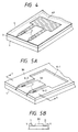
- Fig. 1 is a preferable example of the liquid jet recording head of the present invention, Fig. 1A being a perspective view of its principal portion, Fig. 1B a sectional view cut along the line C-C in Fig. 1A.
- the liquid jet recording head comprises basically a substrate 1, a liquid path wall 3H comprising a resin cured film patterned to a predetermined shape and a cover 7 laminated on the liquid path wall 3H, and by these members are formed an orifice 9 for discharging liquid for recording, liquid paths 6-2 communicated to the orifice and having a portion at which the energy for discharging the liquid for recording acts on the liquid for recording and a liquid chamber 6-1 for storing the liquid for recording to be fed to the liquid paths.
- the thru-holes 8 provided at the cover are bonded feeding pipes for feeding the liquid for recording to the liquid chamber 6-1 externally of the recording head.
- the feeding pipe 10 is omitted. Of course, it may be also directly communicated through the thru-hole 8 to the inner portion of the vessel for housing the liquid for recording.
- the energy for discharging the liquid for recording is generated by applying a discharge signal as desired on the discharge energy generating elements 2 of various types such as heat-generating element, piezoelectric element, etc. arranged at predetermined positions of the portion where discharging energy is permitted to act on the liquid for recording constituting a part of the liquid path 6-2 through the wiring (not shown) connected to these elements.
- the substrate 1 constituting the recording head of the present invention comprises glass, ceramics, plastic or metal, etc., and the generating elements 2 are arranged in desired number at predetermined positions.
- the generating elements 2 are arranged in desired number at predetermined positions.
- two generating elements are provided, but the number and arrangement of the heat-generating elements may be suitably determined depending on the predetermined constitution.
- the cover 7 comprises a flat plate of glass, ceramics, plastic or metal, etc., which is bonded onto the liquid path wall 3H by the bonding method by fusion or by use of an adhesive, and the thru-holes 8 for connecting the feeding pipes 10 are provided at predetermined positions.
- the resin cured film patterned to a predetermined shape constituting the wall 3H of the liquid path 6-2 and the liquid chamber 6-1 is obtained by subjecting the layer comprising the active energy-ray-curing resin composition including the constituent components (A) to (D) as described above provided on the substrate 1 or on the cover 7 to patterning according to the photolithographic steps.
- the cured film (cured product) of the resin composition can be suitably utilized for other portions of the recording head.
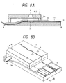
- Figs. 7A to 7H represented as a partial section of a recording head vertical to the liquid paths, there can be mentioned utilization of the cured product of the resin composition :
- the recording head of the present invention may be also one having a structure for discharging liquid in the direction vertical to the liquid path (6-2) shown in Figs. 8A and 8B and Fig. 9, and in that case, for example, the cured film of the resin composition can be suitably utilized for the same portions as shown in Fig. 7, such as the portions in Figs. 10A and 10B.
- active energy-ray-curing resin composition comprising the constituents (A) to (D) as mentioned above to be used in the constitution of the recording head of the present invention are described.
- the resin composition (known as such from EP-A-307920), particularly when formed into a cured film, has excellent characteristics as a constituent member of a liquid jet recording head such that it has good adhesion to various members such as a substrate, etc. comprising glass, plastic, ceramics, etc., and is excellent also in resistance to the liquid for recording such as ink and mechanical strength, and yet can form a pattern which is precise and of high resolution by patterning with an active energy ray.
- the resin composition can be also used as the dry film, and also in that case the excellent characteristics as mentioned above can be exhibited.
- the trunk chain of the graft-copolymerized polymer (A) mainly comprises the structural unit derived from at least one monomer selected from the group consisting of a monomer containing, in the molecule, a (meth)acryloyl group and a dicyclopentenyl derivative group represented by the general formula (I): where Z represents a 5 - membered ring shown by R4 and R5 each represents a hydrogen atom or an alkyl group with 1 to 3 carbon atoms, a monomer represented by the following general formula II : where R6 - R13 each represents a hydrogen atom or a methyl group, alkyl methacrylate, acrylonitrile and styrene.
- the (meth)acryloyl group includes acryloyl group and methacryloyl group.
- the dicyclopentenyl (meth)acrylate derivative has the feature that the glass transition point is high and hygroscopic property is low and it can provide the composition with higher heat resistance and durability.
- the derivative there can be mentioned compounds of the following structures:
- the blending ratio within a range from 1 to 30 % by weight is particularly preferred.
- the compound shown by the general formula (II) described above also has a feature that the glass transition points is high and the hygroscopic property is low, and it can provide the composition with higher heat resistance and durability like that the compound shown by the general formula (I) described above.
- the blending ratio within a range from 1 to 30% by weight is particularly preferred as well.
- the trunk chain having the above construction is added the graft chain having structural units derived from the above mentioned monomer component (a), whereby the graft copolymerized polymer (A) is constructed.
- hydrophobic monomer as the component of the copolymerization in an amount of about 25 mol% or less.
- the above graft copolymerized polymer (A) can be prepared according to known methods, specifically by various methods as disclosed in "Base and Application of Polymer Alloy” p.10-35 (edited by Polymer Society of Japan, published by Tokyo Kogaku Dojin K.K., 1981). Examples of those methods include (1) the chain transfer method, (2) the method by use of radiation, (3) the oxidation polymerization method, (4) the ion graft polymerization method and (5) macromonomer method.
- the above graft copolymerized polymer (A) can be properly prepared using the foregoing monomers under proper polymerization conditions which make it possible to obtain a desired graft copolymerized polymer having a number average molecular weight of 5,000 or more and a weight average molecular weight of 50,000 or less.
- the methods of (4) and (5) are preferred since the lengths of the graft chains of copolymerized polymer (A) may be easily uniformed. And, the macromonomer method of (5) is most preferred in view that it is advantageous in design of materials.
- the foregoing linear polymer (B) may be properly prepared in accordance with the conventional polymerization method using the foregoing monomer (b) as the main component and also using the foregoing monomer (a′) under properly selected polymerization conditions which permit production of a linear polymer having a number average molecular weight of 50,000 or more and a weight average molecular weight of 350,000 or less and having a glass transition temperature of 60°C or more.
- the monomer (a′) in an amount of 5 to 30 mol% for the following reasons. That is, when more than 30 mol% of the monomer (a′) is incorporated into a linear polymer to be obtained, there are disadvantages that the polar group content in a cured paint film will be undesirably heightened and because of this, any improvement cannot be attained in its adhesiveness with a substrate, and in addition to this, the resulting cured film will be such that is poor in the water proof. On the other hand, when less than 5 mol% of the monomer (a′) is incorporated into a linear polymer to be obtained, not only the adhesiveness with substrate but also the effects of a paint film as the binder will be insufficient.
- the monomer (C) having an ethylenically unsaturated bonds as one ingredient used for the composition in this invention is the ingredient for providing an active energy ray curability to the composition of this invention and various known monomers having a boiling point higher than 100°C under the atmospheric pressure and, more preferably, those having two or more ethylenically unsaturated bond and curable under the irradiation of active energy rays can be used.
- Such a monomer having two or more ethylenically unsaturated bonds are, for example, (a) acrylic acid ester or methacrylic acid ester of a polyfunctional epoxy resin having two or more epoxy groups in one molecule, (b) acrylic acid ester or methacrylic acid ester of alkylene oxide adduct of a polyhydric alcohol, (c) polyester acrylate composed of a dibasic acid and a dihydric alcohol having acrylic acid ester group at the terminal end of the molecular chain of the polyester with molecular weight from 500 to 3,000, (d) reaction product of a polyisocyanate and an acrylic acid monomer having hydroxyl group.
- the monomers (a) - (d) described above may be urethane-modification products having urethane bonds in the molecule.
- acrylic acid or methacrylic acid esters of epoxy resins typically represented by bisphenol-A, novolak or cycloaliphatic type, or bisphenol-S, bisphenol-F, tetrahydroxyphenyl methane tetraglycidyl ether, resorcinol diglycidyl ether, glycerine triglycidyl ether, pentaerythritol triglycidyl ether, isocyanuric acid triglycidyl ether and an epoxy urethane represented by the following general formulae (III) : in which R4 represents an alkylene group or oxyalkylene group and R5 represents or alkylene group.
- R4 represents an alkylene group or oxyalkylene group
- R5 represents or alkylene group.
- ethylene glycol (dimeth)acrylate diethylene glycol (meth) acrylate
- polyethylene glycol (meth)acrylate 1,6-hexanediol (meth)acrylate
- polyethylene di(meth)acrylate polyethylene di(meth)acrylate
- pentaerythritol tri(meth)acrylate etc.
- reaction products of polyisocyanate such as tolylene diisocyanate, isophorone diisocyanate, hexamethylene diisocyanate, lysin diisocyanate and diphenylmethane diisocyanate with an acrylic monomer containing hydroxyl group
- reaction products of polyisocyanate such as tolylene diisocyanate, isophorone diisocyanate, hexamethylene diisocyanate, lysin diisocyanate and diphenylmethane diisocyanate with an acrylic monomer containing hydroxyl group
- reaction product obtained by adding (meth)acrylic acid ester containing hydroxyl group to polyisocyanate compound known under the trade names of Sumidule M (buret derivative of hexamethylene diisocyanate), Sumidule L (trimethylol propane modification product of tolylene diisocyanate) (manufactured by Sumitomo Bayer Urethane K.K.)
- the acryl monomer containing hydroxyl group mentioned herein is typically represented by (meth)acrylic acid ester, and hydroxyethyl acrylate, hydroxyethyl methacrylate and hydroxypropyl acrylate are preferred.
- other acryl monomers containing hydroxyl group used for the branch of the graft copolymerized polymer mentioned above, particularly, the compound represented by the general formula (x) can also be used.
- the monomer for example, mentioned below having only one ethylenically unsaturated bond can be used together.
- carboxyl-containing unsaturated monomer such as acrylic acid and methacrylic acid
- glycidyl-containing unsaturated monomer such as glycidyl acrylate and glycidyl methacryalte
- C2 - C8 hydroxyalkyl ester of acrylic acid or methacrylic acid such as hydroxyethyl acrylate, hydroxyethyl methacrylate, hydroxypropyl acrylate and hydroxypropyl methacrylate
- monoester of acrylic acid or methacrylic acid with polyethylene glycol or polypropylene glycol such as polyethylene glycol monoacrylate, polyethylene glycol monomethacryalte
- the resin composition curable with active energy ray containing the above components is curable under the irradiation of active energy ray described later and it is preferred to add a photopolymerization initiator in the resin composition.
- photopolymerization initiator (D) known substances activated by the active energy ray to generate free organic radicals thereby starting the radical polymerization can be used with no particular restriction.
- photopolymerization initiator that can be used preferably herein are, for example, benzyl; benzoin alkyl ether such as benzoin isobutyl ether, benzoin isopropyl ether, benzoin-n-butyl ether, benzoin ethyl ether and benzoin methyl ether; benzophenones such as benzophenone, 4,4′-bis(N,N-diethylamino)benzophenone and benzophenone methyl ether; anthraquinones such as 2-ethyl anthraquinone and 2-tert-butyl anthraquinone; xanthones such as 2,4-dimethyl thioxanthone and 2,4-diisopropyl thioxanthone; acetophenones such as 2,2-dimethoxy-phenyl acetophenone, ⁇ , ⁇ -dichloro-4-phenoxy acetophenone,
- amino compound use for the photopolymerization promotor there can be mentioned, for example, ethanolamine, ethyl-4-dimethylamino benzoate, 2-(dimethylamino)ethyl benzoate, p-dimethylamino benzoic acid n-amylester, p-dimethylamino benzoic acid isoamyl ester.
- the constitutional ratios in the active energy-ray-curing resin composition according to this invention are properly determined upon the application purpose or a position to be used in the liquid jet recording head.
- condensation crosslinking catalysts thermal polymerization inhibitors, colorants such as dyes, pigments, etc., thermal stabilizers such as hydroquinone, p-methoxyphenol, etc., close contact accelerators, plasticizers, extender pigments such as silica, talc, etc., leveling agents which give coating adaptability and so on.
- condensation crosslinking catalyst sulfonic acids as represented by p-toluenesulfonic acid, carboxylic acids such as formic acid, etc. may be included.
- thermal polymerization inhibitor hydroquinone and derivatives thereof, p-methoxyphenol, phenothiazine, etc. may be included.
- colorant oil-soluble dyes and pigments can be added within the range which does not substantially interfere with transmission of the active energy ray.
- filler for hardness elevation of the coating, elevation of coloration, close contact, mechanical strength, extender pigments, plastic fine particles, etc. used in coating materials in general may be employed.
- the close contact accelerator there are silane coupling agents as the inorganic surface modifier, low molecular weight surfactant, etc.
- hydrophilic solvents such as alcohols, glycol ethers, glycol esters, etc. may be included.
- hydrophilic solvents such as alcohols, glycol ethers, glycol esters, etc.
- mixtures based primarily on these hydrophilic solvents optionally mixed suitably with ketones such as methyl ethyl ketone, methyl isobutyl ketone, etc.; esters such as ethyl acetate, isobutyl acetate, etc.; aromatic hydrocarbons such as toluene, xylene, etc. and halogen derivatives thereof; aliphatic solvents containing chlorine such as methylene chloride, 1,1,1-trichloroethane, etc. These solvents can be also used as the developer of said resin composition.
- the resin composition can be formed into a cured layer on a substrate and the like according to conventional methods.
- the active energy-ray-curing resin composition contains a monomer represented by the above general formula (x), it is desirable to further effect condensation curing of the cured film obtained by the methods (1) to (4) as described above by subjecting it to heating treatment at a temperature of 80 °C to 200 °C.
- UV-ray or electron beam already practically applied widely may be employed as the active energy ray to be used for curing the active energy-ray-curing resin composition, or pattern exposure onto the resin composition, etc.
- the UV-ray light source high pressure mercury lamps, ultra-high pressure mercury lamps, metal halide lamps, etc. enriched in light with wavelengths of 250 nm to 450 nm may be included, and one with a light intensity in the vicinity of 365 nm of about 1 mW/cm2 to 100 mW/cm2 at a practically tolerable distance between the lamp and the material to be irradiated may be preferred.
- the electron beam irradiation apparatus is not particularly limited, but an apparatus having a dose within the range from 0.5 to 20 M Rad is practically suitable.
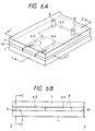
- Fig. 2 to Fig. 6B are schematic diagrams for illustration of the preparation procedure of the liquid jet recording head of the present invention.
- discharge energy generating devices 2 such as heat generating element, piezoelectric elements, etc. are arranged in a desired number on the substrate 1 of glass, ceramic, plastic or metal, etc. If necessary, for imparting resistance to the liquid for recording, electrical insulation, etc. to the surface of the substrate, said surface may be coated with a protective layer of SiO2, Ta2O5, glass, etc.
- electrodes for inputting recording signals are connected, although not shown.
- the above-described active energy-ray-curing resin composition 3 of the dry film type (film thickness: about 20 ⁇ m to 200 ⁇ m) is heated to about 40 to 130 °C, and laminated on the substrate surface 1A under the conditions of, for example, a speed of 0.5 to 0.4 f/min. and pressurization of 1 to 3 Kg/cm2.
- Alignment between the photomask 4 and the substrate 1 is effected so that the above elements 2 may be positioned in the liquid path regions formed finally via the steps of exposure, developing processing, etc., and can be practiced according to the method in which alignment marks are drawn respectively on the substrate 1 and the mask 4, and alignment is effected following the marks.
- the portions other than the region covered with the above-mentioned pattern, namely the portion of the dry film layer 3 exposed is cured by polymerization to become solvent insoluble, while the portion not exposed remains solvent soluble.
- suitable one may be selected and used from among active energy rays known in the art depending on the kinds of the components of the above-described active energy ray curing resin composition, including specifically, for example, high pressure mercury lamp, ultra-high pressure mercury lamp, metal halide lamp, carbon arc lamp, electron beam, etc.
- UV-ray light source high pressure mercury lamp, ultra-high pressure mercury lamp, metal halide lamp, etc. enriched in light with wavelengths of 250 nm to 450 nm may be included, and one with a light intensity in the vicinity of 365 nm of about 1 mW/cm2 to 100 mW/cm2 at a practically tolerable distance between the lamp and the object to be irradiated may be preferred.
- the electron beam irradiation apparatus is not particularly limited, but an apparatus having a dose within the range from 0.5 to 20 M Rad is practically suitable.
- the exposed dry film 3 is subjected to developing processing by dipping into a volatile organic solvent such as 1,1,1-trichloroethane, etc., thereby dissolving away the unpolymerized (uncured) portion of the dry film layer 3 on the substrate 1 which is solvent soluble to form the groove which becomes finally the liquid paths 6-2 and the liquid chamber 6-1 with the resin cured film 3H remaining on the substrate 1, as shown in Figs. 5A and 5B.
- a volatile organic solvent such as 1,1,1-trichloroethane, etc.
- the cured resin film 3H on the substrate 1 is heated at a temperature of at least 80 °C for about 10 minutes to 3 hours to carry out thermal polymerization.
- the heating treatment is made a temperature of at least 100 °C for about 5 to 60 minutes.
- the method for forming a layer comprising a liquid resin composition by use of the composition on the substrate for example, there may be employed the method by means of squez used during preparation of a relief image, namely in which a wall of a height corresponding to the thickness of a coating of a desired composition is provided around the substrate, and superfluous resin composition is removed by a squong.
- the viscosity of the resin composition may be appropriately 100 cp to 3000 cp.
- the height of the wall placed around the substrate is required to be determined by taking into account the reduction of the solvents contained in the photosensitive resin composition by evaporation.
- the method of plastering a dry film onto a substrate by heating pressure contact as described above is suitable.
- the solid film type is convenient in handling, or with respect to easy and accurate control of the thickness.
- the cover 7 As a specific method for providing the cover 7, there is, for example, the method in which the flat plate 7 of glass, ceramic, metal, plastic, etc. is spin coated with an epoxy type adhesive to a thickness of 3 to 4 ⁇ m, then preheated to effect the so called B-staging and plastering this onto the cured dry film 3H, followed by main curing of the above-mentioned adhesive layer, etc.
- the method may be also employed the method not using an adhesive in which the flat plate 7 of a thermoplastic resin such as acrylic resin, ABS resin, polyethylene, etc. is directly thermally fused onto the resin cured film 3H.
- a resin layer comprising the resin composition for formation of a resin cured film in the present invention is provided on the side to be bonded to the liquid path of the cover 7 thermally, fused with the resin cured film 3H having the liquid paths formed, and then heated by irradiation of an active energy ray. That is, this is the method in which the resin composition for formation of a resin cured film in the present invention is used as an adhesive.
- FIGs. 6A and 6B 6-1 shows the liquid chamber, 6-2 the liquid paths, 8 the thru-hole for connecting the feeding pipe (not shown) for feeding the liquid for recording into the liquid chamber from the outside of the recording head to the inside.
- the bonded product is cut along C-C corresponding to the downstream side of the liquid path 6-2 shown in Figs. 6A and 6B to form orifices for discharging the liquid for recording which are openings of the liquid paths at the cut surface.
- This step is done for optimizing the interval between the discharge energy generating device 2 and the orifice 9, and here the region to be cut may be suitably selected.
- the dicing method, etc. conventionally employed in semiconductor industries can be employed.
- the downstream portion of the liquid path as mentioned in the present invention refers to the downstream region in the flow direction of the liquid for recording when recording is performed by use of a recording head, specifically the portion of the liquid path downstream of the position where the discharge energy generating device 2 is provided.
- the cut surface is polished to be smoothened, and the feeding pipes (not shown) are mounted on the thru-hole 8 to complete the liquid jet recording head as shown in Figs. 1A and 1B.
- the cover 7 is bonded thereto, but it is also possible to form the resin cured film 3H on the side of the cover 7 and then bond it to the substrate 1. Also, the liquid paths 6-2 and the liquid chamber 6-1 may be separately formed.
- Fig. 11 is a perspective view schematically showing an embodiment of the liquid ejection recording apparatus of the present invention.
- reference numeral 119 designates recording paper.
- the recording paper 119 is moved on a platen 115 at a predetermined speed in the subsidiary scanning direction (the direction of arrow A) by a paper feeding roller 114 and a pinch roller 116.
- Reference numeral 117 and 118 denote pulleys supported on respective shafts and rotated by a drive source (not shown).
- a carriage driving belt 112 is passed over the pulleys 117 and 118.
- a carriage 113 is integrally fixed to the carriage driving belt 112.
- the carriage 113 is guided by guide shafts 108 and 111 and is reciprocally movable in the major scanning directions (the directions of arrow B) by the rotation of the pulleys 117 and 118 a roller 120 adapted to roll on the guide shaft 111 is disposed on the underside of the carriage 113.
- a connector 122 electrically connected to flexible wiring 121 is disposed substantially in the central portion of the carriage 113, and a head aligner 123 or aligning the liquid ejection recording head (hereinafter referred to as the recording head) 101 when the wires of the recording head 101 are connected and fixed to the connector 122 is vertically provided on the carriage 113. Accordingly, the recording head 101 is removable from the carriage 113 by the connector 122. Also, a sensor 124 for detecting the home position of the carriage 113 is provided.
- the recording head 101 has a substrate 106, which in turn has thereon discharge ports 102 for discharging ink droplets which are flying droplets, a liquid flow path constituting portion 103 for constituting liquid flow paths communicating with the discharge ports 102 and having energy generating members such as heat generating elements for forming flying ink droplets, and an ink chamber for storing therein ink to be supplied to the liquid flow paths.
- a driving voltage is supplied from a driving voltage generating circuit 129 (not shown) through the connector 122 and the flexible wiring 121 and also, a discharge control signal for controlling the discharge of ink droplets from the discharge ports 102.
- materials (A) to (D) shown below were prepared.
- Radical chain transfer polymerization of 50 parts by weight of 2-hydroxyethylmethacrylate and 50 parts by weight of N-methylolacrylamide was carried out using thioglycollic acid as the chain transferring agent and azobisisobutyronitrile as the polymerization initiator to obtain an oligomer having a carboxyl group at the terminal end of the molecular chain.
- This oligomer was reacted with glycidylmethacrylate to obtain a macromonomer having a methacryloyl group at one terminal end of the molecular chain.
- the result of the measurement by the known GPC method gave a value of about 3,000 for the number average molecular weight of the resultant macromonomer.
- Solution polymerization of 20 parts by weight of the said macromonomer and 80 parts by weight of methylmethacrylate was carried out in methyl cellosolve solvent to thereby obtain a graft copolymerized polymer having a weight average molecular weight of about 40,000 and a number average molecular weight of about 10,000.
- linear acrylic copolymer obtained by polymerizing methylmethacrylate, tricyclodecaneoxyethylmethacrylate and N-methylolacrylamide in the molar ratio of 80:10:10.
- This linear acrylic copolymer is one that has a number average molecular weight of about 100,000 and a weight average molecular weight of about 270,000.
- a photopolymerization initiator (D) A photopolymerization initiator (D)
- a laminate was obtained according to the same method as described above other than that the thickness of a dry film obtained by coating with reverse coater is 35 ⁇ m.
- a plurality of heat-generating devices were arranged at predetermined positions on a substrate comprising silicon, and electrodes for application of recording signals were connected to these.
- a SiO2 layer (thickness 1.0 ⁇ m) as the protective layer was provided on the substrate surface having heat-generating devices arranged thereon, and after the surface of the protective layer was cleaned and dried, the dry film with a thickness of 50 ⁇ m obtained in Synthesis example 1 heated to 120 °C was laminated on the protective layer by use of a rubber roll under the conditions of a roll temperature of 120 °C and a circumferential speed of 1.0 m/min, while peeling off the polyethylene film.
- the polyethylene terephthalate film was peeled off from the dry film on the substrate, and then said dry film was subjected to spray developing processing with 1,1,1-trichloroethane (trade name Eterner Nu) at 20 °C for 50 seconds, thereby dissolving away the unpolymerized (uncured) portion of the dry film to form a groove which becomes finally the liquid path and the liquid chamber with the wall comprising the cured dry film remaining on the substrate.
- 1,1,1-trichloroethane trade name Eterner Nu
- post-exposure UV post-cure
- a ultra-high pressure mercury lamp under the same conditions as previously used for pattern exposure for 5 minutes, and further heating treatment was performed to apply post-curing treatment at 150 °C for 15 minutes.
- the groove which becomes the liquid path and the liquid chamber was formed with a wall comprising the cured dry film.
- the dry film with a film thickness of 35 ⁇ m obtained in Synthesis example 1 heated to 120 °C by use of a rubber roll under the conditions of a roll temperature of 100 °C and a circumferential speed of 1.0 m/min. on a glass plate which becomes the ceiling plate while peeling off the polyethylene film.
- the polyethylene terephthalate film remaining on the dry film on the glass plate was peeled off, and developing processing, mercury lamp irradiation treatment and heating treatment were applied under the same conditions as in the step of forming the liquid path and the liquid chamber on the substrate as described above, to form a ceiling equipped with the liquid chamber.
- the liquid active energy-ray-curing resin composition obtained in Synthesis example 1 was coated by a roll coater, dried in hot air at 80 °C for 5 minutes to form a resin layer for adhesion with a thickness of 3 ⁇ m, and said ceiling plate was plastered on the upper surface side of the cured dry film on the above substrate with said resin layer interposed. Further, the substrate was bonded under pressurization to the flat plate, followed further by irradiation of a UV-ray at 50 mW/cm2 for 60 seconds from the ceiling plate side to cure completely the resin layer for adhesion, thereby effecting fixing by adhesion of the substrate and the ceiling plate to form a bonded product.
- the cut surface was washed and then dried, followed further by polishing of the cut surface to effect smoothening and mounting of the feeding pipe of the liquid for recording on the thru-hole to complete the liquid jet recording head.
- the recording heads obtained were all found to be excellent dimensional precision having liquid paths and liquid chambers reproducing faithfully the mask pattern.
- the orifice dimensions were within the ranges of longitudinally 50 ⁇ 5 ⁇ m, laterally 70 ⁇ 5 ⁇ m, and the orifice pitch within the range of 120 ⁇ 5 ⁇ m.
- the durability test of performing the dipping treatment in the liquids for recording comprising the following compositions at 60 °C for 1000 hours (the environmental conditions comparable with those during the actual prolonged use of recording heads) was practiced.
- the notes *1 to *4 are water-soluble dyes, and sodium hydroxide was employed for pH control.
- the recording head of the present invention comprises the structural member with little influence on the ink jet ink.
- each head was mounted on the recording apparatus shown in Fig. 11, and the printing test was practiced, which performed printing by use of the liquid for recording as mentioned above by applying a recording signal of 108 pulses on the recording head continuously for 14 hours.
- the active energy-ray-curing resin composition used in the constitution of the liquid jet recording head of the present invention comprises the graft copolymerized component (A) as the constituent and therefore has sufficient adhesion to various members without addition of an additive, and also contains the linear polymer (B) as the constituent and is therefore excellent in developing characteristics during pattern formation. Also, its cured film has sufficient chemical resistance and durability.
- the composition employs the graft copolymerized polymer and the linear polymer as the polymeric substances which are its constituents in combination, and therefore a coating with solvent resistance to the developer is obtained with less active energy irradiation as compared with the case when employing only the graft copolymerized polymer alone as the polymeric substance.
- the properties of the patterning process are improved, such that resolution can be improved and pattern formation can be effected without being influenced by the kinds or the states of the members, etc., whereby the working conditions width can be expanded.
- said composition contains a monomer having an ethylenically unsaturated bond as the main component of the active energy ray-curing composition, excellent sensitivity and resolution are exhibited when used in combination with the polymeric substance component as described above. Therefore, as the recording head, it is rendered possible to prepare a high density nozzle having practical durability.
- the recording head of the present invention becomes to have a highly crosslinked structure, without chemical denaturation received from the ink jet ink, and at the same time with the dissolved components into the ink being very small. From the above-mentioned two facts, the recording head is by far superior in durability both mechanically and chemically.
- the recording head of the present invention which employs the cured product of the composition as at least a part of its constitution is inexpensive and precise, and becomes higher in reliability. Also, by formation of the liquid path wall with the cured film of the composition, a recording head having the liquid path finely worked with good precision and good yield can be obtained.
- the recording head of the present invention by having the constitution as described above, becomes higher in reliability and excellent in durability also when formed into a multi-orifice type.
Landscapes
- Engineering & Computer Science (AREA)
- Manufacturing & Machinery (AREA)
- Chemical & Material Sciences (AREA)
- Chemical Kinetics & Catalysis (AREA)
- Physics & Mathematics (AREA)
- Medicinal Chemistry (AREA)
- General Physics & Mathematics (AREA)
- Health & Medical Sciences (AREA)
- Spectroscopy & Molecular Physics (AREA)
- Polymers & Plastics (AREA)
- Organic Chemistry (AREA)
- Particle Formation And Scattering Control In Inkjet Printers (AREA)
- Graft Or Block Polymers (AREA)
- Common Mechanisms (AREA)
- Polymerisation Methods In General (AREA)
- Addition Polymer Or Copolymer, Post-Treatments, Or Chemical Modifications (AREA)
Claims (28)
- Flüssigkeitstrahl-Aufzeichnungskopf, der mindestens als Teil seines Aufbaus ein gehärtetes Produkt einer durch aktiven Energiestrahl härtenden Harzzusammensetzung umfaßt, wobei die Zusammensetzung die nachstehenden Bestandteile umfaßt:(A) ein pfropfcopolymerisiertes Polymer mit einem Zahlenmittel des Molekulargewichts von 5.000 oder mehr und einem Gewichtsmittel des Molekulargewichts von 50.000 oder weniger, das eine Gerüstkette umfaßt, die hauptsächlich aus Struktureinheiten zusammengesetzt ist, die sich von mindestens einem Monomer ableiten, ausgewählt aus der Gruppe bestehend aus einem Monomer, das im Molekül eine (Meth)acryloylgruppe und eine Dicyclopentenylderivatgruppe enthält, dargestellt durch die allgemeine Formel (I):


 (B) ein lineares Polymer mit einem Zahlenmittel des Molekulargewichts von 50.000 oder mehr und einem Gewichtsmittel des Molekulargewichts von 350.000 oder weniger und mit einer Glasübergangstemperatur von 60°C oder höher, das Struktureinheiten umfaßt, abgeleitet von mindestens einem Monomer, ausgewählt aus der Gruppe bestehend aus Methylmethacrylat, Ethylmethacrylat, Isobutylmethacrylat, t-Butylmethacrylat, Benzylmethacrylat, Acrylonitril, Isobornylmethacrylat, Isobornylacrylat, Tricyclodecanmethacrylat, Tricyclodecanoxyethylmethacrylat, Styrol, Dimethylaminoethylmethacrylat und Cyclohexylmethacrylat und das Struktureinheiten umfaßt, abgeleitet von mindestens einem Monomer, ausgewählt aus der Gruppe bestehend aus den Monomeren, dargestellt durch die vorstehend beschriebene Formel (x) und die vorstehend beschriebene Formel (y);(C) ein Monomer mit ethylenisch ungesättigter Bindung, und(D) einen mittels der Bestrahlung mit einem aktiven Energiestrahl zur Erzeugung freier Radikale geeigneten Photopolymerisationsinitiator;
 - Aufzeichnungskopf nach Anspruch 1, wobei für das Gewichtsverhältnis von dem pfropfcopolymerisierten Polymer (A) zu dem linearen Polymer (B) gilt: (A) : (B) = 80 : 20 bis 50 : 50.
- Aufzeichnungskopf nach Anspruch 1 oder Anspruch 2, wobei für das Gewichtsverhältnis des Gesamtgewichts aus dem pfropfcopolymerisierten Polymer (A) und dem linearen Polymer (B) zu dem Monomer (C) gilt: ((A) + (B)) : (C) = 100 : 50 bis 100 : 200.
- Aufzeichnungskopf nach einem der Ansprüche 1 bis 3, wobei für das Gewichtsverhältnis des Gesamtgewichts aus dem pfropfcopolymerisierten Polymer (A), dem linearen Polymer (B) und dem Monomer (C) zu dem Gewicht des Photopolymerisationsinitiators (D) gilt: ((A) + (B) + (C)) : (D) = 100 : 1 bis 100 : 10.
- Aufzeichnungskopf nach Anspruch 1, wobei der Teil ein Element ist, bei dem eine Ausstoßöffnung zum Ausstoßen von Tinte ausgebildet ist.
- Aufzeichnungskopf nach Anspruch 1, wobei der Teil ein Element ist, das einen Flüssigkeitskanal definiert, der mit einer Ausstoßöffnung zum Ausstoßen von Tinte verbunden ist.
- Aufzeichnungskopf nach Anspruch 6, wobei das Element, das den Flüssigkeitskanal definiert, eine Flüssigkeitskanalwandung ist.
- Aufzeichnungskopf nach Anspruch 1, wobei der Teil ein Element ist, das auf einem Element vorgesehen ist, das einen Flüssigkeitskanal definiert, der mit einer Ausstoßöffnung zum Ausstoßen von Tinte verbunden ist
- Aufzeichnungskopf nach Anspruch 8, wobei das vorgesehene Element als eine Haftschicht verwendet wird.
- Aufzeichnungskopf nach Anspruch 8, wobei das vorgesehene Element eine flache Platte ist.
- Aufzeichnungskopf nach Anspruch 1, der ein Element zur Erzeugung von Ausstoßenergie umfaßt.
- Aufzeichnungskopf nach Anspruch 11, wobei das Element zur Erzeugung von Ausstoßenergie ein Element zur Erzeugung von Wärme ist.
- Aufzeichnungskopf nach Anspruch 11, wobei das Element zur Erzeugung von Ausstoßenergie ein piezoelektrisches Element ist.
- Aufzeichnungskopf nach Anspruch 11, wobei eine Ausstoßöffnung zum Ausstoßen von Tinte so angeordnet ist, daß sie dem Element zur Erzeugung von Ausstoßenergie gegenüberliegt.
- Flüssigkeitsstrahl-Aufzeichnungsgerät, umfassend einen Flüssigkeitsstrahl-Aufzeichnungskopf mit einer Ausstoßöffnung zum Ausstoßen der Aufzeichnungsflüssigkeit, eine Antriebsschaltung zum Antrieb des Aufzeichnungskopfes und eine Platte, wobei der Flüssigkeitsstrahl-Aufzeichnungskopf mindestens als Teil seines Aufbaus ein gehärtetes Produkt einer durch aktiven Energiestrahl härtenden Harzzusammensetzung umfaßt, wobei die Zusammensetzung die nachstehenden Bestandteile umfaßt:(A) ein pfropfcopolymerisiertes Polymer mit einem Zahlenmittel des Molekulargewichts von 5.000 oder mehr und einem Gewichtsmittel des Molekulargewichts von 50.000 oder weniger, das eine Gerüstkette umfaßt, die hauptsächlich aus Struktureinheiten zusammengesetzt ist, die sich von mindestens einem Monomer ableiten, ausgewählt aus der Gruppe bestehend aus einem Monomer, das im Molekül eine (Meth)acryloylgruppe und eine Dicyclopentenylderivatgruppe enthält, dargestellt durch die allgemeine Formel (I):


 (B) ein lineares Polymer mit einem Zahlenmittel des Molekulargewichts von 50.000 oder mehr und einem Gewichtsmittel des Molekulargewichts von 350.000 oder weniger und mit einer Glasübergangstemperatur von 60°C oder höher, das Struktureinheiten umfaßt, abgeleitet von mindestens einem Monomer, ausgewählt aus der Gruppe bestehend aus Methylmethacrylat, Ethylmethacrylat, Isobutylmethacrylat, t-Butylmethacrylat, Benzylmethacrylat, Acrylonitril, Isobornylmethacrylat, Isobornylacrylat, Tricyclodecanmethacrylat, Tricyclodecanoxyethylmethacrylat, Styrol, Dimethylaminoethylmethacrylat und Cyclohexylmethacrylat und das Struktureinheiten umfaßt, abgeleitet von mindestens einem Monomer, ausgewählt aus der Gruppe bestehend aus den Monomeren, dargestellt durch die vorstehend beschriebene Formel (x) und die vorstehend beschriebene Formel (y);(C) ein Monomer mit ethylenisch ungesättigter Bindung, und(D) einen mittels der Bestrahlung mit einem aktiven Energiestrahl zur Erzeugung freier Radikale geeigneten Photopolymerisationsinitiator;
 - Aufzeichnungsgerät nach Anspruch 15, wobei für das Gewichtsverhältnis von dem pfropfcopolymerisierten Polymer (A) zu dem linearen Polymer (B) gilt: (A) : (B) = 80 : 20 bis 50 : 50.
- Aufzeichnungsgerät nach Anspruch 15 oder Anspruch 16, wobei für das Gewichtsverhältnis des Gesamtgewichts aus dem pfropfcopolymerisierten Polymer (A) und dem linearen Polymer (B) zu dem Monomer (C) gilt: ((A) + (B)) : (C) = 100 : 50 bis 100 : 200.
- Aufzeichnungsgerät nach einem der Ansprüche 15 bis 17, wobei für das Gewichtsverhältnis des Gesamtgewichts aus dem pfropfcopolymerisierten Polymer (A), dem linearen Polymer (B) und dem Monomer (C) zu dem Gewicht des Photopolymerisationsinitiators (D) gilt: ((A) + (B) + (C) : (D)) = 100 : 1 bis 100 : 10.
- Aufzeichnungsgerät nach Anspruch 15, wobei der Teil ein Element ist, bei dem eine Ausstoßöffnung zum Ausstoßen von Tinte ausgebildet ist.
- Aufzeichnungsgerät nach Anspruch 15, wobei der Teil ein Element ist, das einen Flüssigkeitskanal definiert, der mit einer Ausstoßöffnung zum Ausstoßen von Tinte verbunden ist.
- Aufzeichnungsgerät nach Anspruch 20, wobei das Element, das den Flüssigkeitskanal definiert, eine Flüssigkeitskanalwandung ist.
- Aufzeichnungsgerät nach Anspruch 15, wobei der Teil ein Element ist, das auf einem Element vorgesehen ist, das einen Flüssigkeitskanal definiert, der mit einer Ausstoßöffnung zum Ausstoßen von Tinte verbunden ist
- Aufzeichnungsgerät nach Anspruch 22, wobei das vorgesehene Element als eine Haftschicht verwendet wird.
- Aufzeichnungsgerät nach Anspruch 22, wobei das vorgesehene Element eine flache Platte ist.
- Aufzeichnungsgerät nach Anspruch 15, der ein Element zur Erzeugung von Ausstoßenergie umfaßt.
- Aufzeichnungsgerät nach Anspruch 25, wobei das Element zur Erzeugung von Ausstoßenergie ein Element zur Erzeugung von Wärme ist.
- Aufzeichnungsgerät nach Anspruch 25, wobei das Element zur Erzeugung von Ausstoßenergie ein piezoelektrisches Element ist.
- Aufzeichnungsgerät nach Anspruch 25, wobei eine Ausstoßöffnung zum Ausstoßen von Tinte so angeordnet ist, daß sie dem Element zur Erzeugung von Ausstoßenergie gegenüberliegt.
Priority Applications (4)
| Application Number | Priority Date | Filing Date | Title |
|---|---|---|---|
| DE69012096T DE69012096T2 (de) | 1990-03-22 | 1990-03-22 | Flüssigkeitsstrahlaufzeichnungskopf und Aufzeichnungsgerät, versehen mit diesem Kopf. |
| AT90105465T ATE110636T1 (de) | 1990-03-22 | 1990-03-22 | Flüssigkeitsstrahlaufzeichnungskopf und aufzeichnungsgerät, versehen mit diesem kopf. |
| EP90105465A EP0447588B1 (de) | 1990-03-22 | 1990-03-22 | Flüssigkeitsstrahlaufzeichnungskopf und Aufzeichnungsgerät, versehen mit diesem Kopf |
| US08/403,115 US5558975A (en) | 1990-03-21 | 1995-03-13 | Liquid jet recording head and recording apparatus having same |
Applications Claiming Priority (2)
| Application Number | Priority Date | Filing Date | Title |
|---|---|---|---|
| EP90105465A EP0447588B1 (de) | 1990-03-22 | 1990-03-22 | Flüssigkeitsstrahlaufzeichnungskopf und Aufzeichnungsgerät, versehen mit diesem Kopf |
| US08/403,115 US5558975A (en) | 1990-03-21 | 1995-03-13 | Liquid jet recording head and recording apparatus having same |
Publications (2)
| Publication Number | Publication Date |
|---|---|
| EP0447588A1 EP0447588A1 (de) | 1991-09-25 |
| EP0447588B1 true EP0447588B1 (de) | 1994-08-31 |
Family
ID=26125042
Family Applications (1)
| Application Number | Title | Priority Date | Filing Date |
|---|---|---|---|
| EP90105465A Expired - Lifetime EP0447588B1 (de) | 1990-03-21 | 1990-03-22 | Flüssigkeitsstrahlaufzeichnungskopf und Aufzeichnungsgerät, versehen mit diesem Kopf |
Country Status (4)
| Country | Link |
|---|---|
| US (1) | US5558975A (de) |
| EP (1) | EP0447588B1 (de) |
| AT (1) | ATE110636T1 (de) |
| DE (1) | DE69012096T2 (de) |
Families Citing this family (8)
| Publication number | Priority date | Publication date | Assignee | Title |
|---|---|---|---|---|
| JP2932877B2 (ja) * | 1992-02-06 | 1999-08-09 | セイコーエプソン株式会社 | インクジェットヘッドの製造方法 |
| DE69419337T2 (de) * | 1993-03-31 | 1999-11-25 | Canon K.K., Tokio/Tokyo | Tinte, Tintenstrahl-Aufzeichnungsverfahren und Vorrichtung unter Verwendung derselben |
| DE69603639T2 (de) * | 1995-03-31 | 2000-04-13 | Canon K.K., Tokio/Tokyo | Verfahren zum Herstellen eines Tintenstrahlkopfes |
| US6086942A (en) | 1998-05-27 | 2000-07-11 | International Brachytherapy S.A. | Fluid-jet deposition of radioactive material for brachytherapy devices |
| US6575562B1 (en) | 1999-11-16 | 2003-06-10 | Lexmark International, Inc. | Performance inkjet printhead chip layouts and assemblies |
| US8157347B2 (en) * | 2005-07-08 | 2012-04-17 | Canon Kabushiki Kaisha | Ink jet recording head and ink jet recording head cartridge |
| JP4790046B2 (ja) * | 2009-05-25 | 2011-10-12 | キヤノン株式会社 | インクジェット記録ヘッド用シールテープ及びこれを用いたインクジェット記録ヘッド |
| JP5858813B2 (ja) | 2012-02-06 | 2016-02-10 | キヤノン株式会社 | 液体吐出ヘッド及びその製造方法 |
Family Cites Families (15)
| Publication number | Priority date | Publication date | Assignee | Title |
|---|---|---|---|---|
| US3760958A (en) * | 1972-05-22 | 1973-09-25 | Kearney & Trecker Corp | Clamping tool changer mechanism and actuating mechanism for a machine tool |
| JPS5214278A (en) * | 1975-07-25 | 1977-02-03 | Nippon Steel Corp | Panel assemly process |
| US4417251A (en) * | 1980-03-06 | 1983-11-22 | Canon Kabushiki Kaisha | Ink jet head |
| JPS5919168A (ja) * | 1982-07-26 | 1984-01-31 | Canon Inc | インクジエツト記録ヘツド |
| JPH0645242B2 (ja) * | 1984-12-28 | 1994-06-15 | キヤノン株式会社 | 液体噴射記録ヘツドの製造方法 |
| JPS61283645A (ja) * | 1985-06-10 | 1986-12-13 | Canon Inc | 活性エネルギ−線硬化型樹脂組成物 |
| EP0206086B1 (de) * | 1985-06-10 | 1992-09-09 | Canon Kabushiki Kaisha | Strahlenhärtbare Harzzusammensetzung |
| JPS61283646A (ja) * | 1985-06-10 | 1986-12-13 | Canon Inc | 活性エネルギ−線硬化型樹脂組成物 |
| DE3620254C2 (de) * | 1985-06-18 | 1994-05-05 | Canon Kk | Durch Strahlen mit wirksamer Energie härtbare Harzmischung |
| US4688054A (en) * | 1985-07-09 | 1987-08-18 | Canon Kabushiki Kaisha | Liquid jet recording head |
| US4688053A (en) * | 1985-07-13 | 1987-08-18 | Canon Kabushiki Kaisha | Liquid jet recording head having a layer of a resin composition curable with an active energy ray |
| US4688052A (en) * | 1985-07-13 | 1987-08-18 | Canon Kabushiki Kaisha | Liquid jet recording head having a layer of a resin composition curable with an active energy ray |
| US4688056A (en) * | 1985-07-13 | 1987-08-18 | Canon Kabushiki Kaisha | Liquid jet recording head having a layer of a resin composition curable with an active energy ray |
| JPH0686505B2 (ja) * | 1986-03-10 | 1994-11-02 | キヤノン株式会社 | 活性エネルギ−線硬化型樹脂組成物 |
| EP0307920B1 (de) * | 1987-09-16 | 1994-01-26 | Canon Kabushiki Kaisha | Strahlenhärtbare Harzzusammensetzung, enthaltend ein Pfropfcopolymer auf einer Pfropfgrundlage mit Dicyclopentadienylgruppe |
-
1990
- 1990-03-22 EP EP90105465A patent/EP0447588B1/de not_active Expired - Lifetime
- 1990-03-22 AT AT90105465T patent/ATE110636T1/de not_active IP Right Cessation
- 1990-03-22 DE DE69012096T patent/DE69012096T2/de not_active Expired - Fee Related
-
1995
- 1995-03-13 US US08/403,115 patent/US5558975A/en not_active Expired - Fee Related
Also Published As
| Publication number | Publication date |
|---|---|
| DE69012096T2 (de) | 1995-01-12 |
| US5558975A (en) | 1996-09-24 |
| ATE110636T1 (de) | 1994-09-15 |
| EP0447588A1 (de) | 1991-09-25 |
| DE69012096D1 (de) | 1994-10-06 |
Similar Documents
| Publication | Publication Date | Title |
|---|---|---|
| US4688056A (en) | Liquid jet recording head having a layer of a resin composition curable with an active energy ray | |
| US4688053A (en) | Liquid jet recording head having a layer of a resin composition curable with an active energy ray | |
| EP0208300B1 (de) | Tintenstrahlauszeichnungskopf | |
| US4688052A (en) | Liquid jet recording head having a layer of a resin composition curable with an active energy ray | |
| US5730889A (en) | Ink jet recording head, fabrication method thereof, and printer with ink jet recording head | |
| US5086307A (en) | Liquid jet recording head | |
| US5578417A (en) | Liquid jet recording head and recording apparatus having same | |
| EP0333169A2 (de) | Tintenstrahlauszeichnungskopf | |
| EP0447588B1 (de) | Flüssigkeitsstrahlaufzeichnungskopf und Aufzeichnungsgerät, versehen mit diesem Kopf | |
| JPS6216147A (ja) | 液体噴射記録ヘツド | |
| JPH04294148A (ja) | 液体噴射記録ヘッド | |
| US5578418A (en) | Liquid jet recording head and recording apparatus having same | |
| EP0265034B1 (de) | Kopf für Tintenstrahlaufzeichnung | |
| EP0265033B1 (de) | Kopf für Tintenstrahlaufzeichnung | |
| EP0209753B1 (de) | Strahlenhärtbare Zusammensetzung | |
| EP0307920B1 (de) | Strahlenhärtbare Harzzusammensetzung, enthaltend ein Pfropfcopolymer auf einer Pfropfgrundlage mit Dicyclopentadienylgruppe | |
| EP0307919B1 (de) | Strahlenhärtbare Harzzusammensetzung, enthaltend ein Epoxyharz und ein Monomer mit einer ungesättigten Bindung | |
| US5571659A (en) | Liquid jet recording head and recording apparatus using same | |
| EP0453581B1 (de) | Flüssigkeitsstrahlaufzeichnungskopf und Aufzeichnungsgerät, versehen mit diesem Kopf | |
| EP0447587B1 (de) | Flüssigkeitsstrahlaufzeichnungskopf und Aufzeichnungsgerät, versehen mit diesem Kopf | |
| EP0447590B1 (de) | Flüssigkeitsstrahlaufzeichnungskopf und Aufzeichnungsgerät, versehen mit diesem Kopf | |
| EP0447591B1 (de) | Flussigkeitsstrahlaufzeichnungskopf und Aufzeichnungsgerät, versehen mit diesem Kopf | |
| EP0447589B1 (de) | Flüssigkeitsstrahlaufzeichnungskopf und Aufzeichnungsgerät, versehen mit diesem Kopf | |
| JPH02131945A (ja) | 液体噴射記録ヘッド | |
| JPS6216150A (ja) | 液体噴射記録ヘツド |
Legal Events
| Date | Code | Title | Description |
|---|---|---|---|
| PUAI | Public reference made under article 153(3) epc to a published international application that has entered the european phase |
Free format text: ORIGINAL CODE: 0009012 |
|
| 17P | Request for examination filed |
Effective date: 19901221 |
|
| AK | Designated contracting states |
Kind code of ref document: A1 Designated state(s): AT BE CH DE DK ES FR GB GR IT LI LU NL SE |
|
| 17Q | First examination report despatched |
Effective date: 19931004 |
|
| GRAA | (expected) grant |
Free format text: ORIGINAL CODE: 0009210 |
|
| AK | Designated contracting states |
Kind code of ref document: B1 Designated state(s): AT BE CH DE DK ES FR GB GR IT LI LU NL SE |
|
| PG25 | Lapsed in a contracting state [announced via postgrant information from national office to epo] |
Ref country code: NL Effective date: 19940831 Ref country code: LI Effective date: 19940831 Ref country code: GR Free format text: LAPSE BECAUSE OF FAILURE TO SUBMIT A TRANSLATION OF THE DESCRIPTION OR TO PAY THE FEE WITHIN THE PRESCRIBED TIME-LIMIT Effective date: 19940831 Ref country code: ES Free format text: THE PATENT HAS BEEN ANNULLED BY A DECISION OF A NATIONAL AUTHORITY Effective date: 19940831 Ref country code: DK Effective date: 19940831 Ref country code: CH Effective date: 19940831 Ref country code: BE Effective date: 19940831 Ref country code: AT Effective date: 19940831 |
|
| REF | Corresponds to: |
Ref document number: 110636 Country of ref document: AT Date of ref document: 19940915 Kind code of ref document: T |
|
| REF | Corresponds to: |
Ref document number: 69012096 Country of ref document: DE Date of ref document: 19941006 |
|
| ET | Fr: translation filed | ||
| ITF | It: translation for a ep patent filed | ||
| PG25 | Lapsed in a contracting state [announced via postgrant information from national office to epo] |
Ref country code: SE Effective date: 19941130 |
|
| REG | Reference to a national code |
Ref country code: CH Ref legal event code: PL |
|
| NLV1 | Nl: lapsed or annulled due to failure to fulfill the requirements of art. 29p and 29m of the patents act | ||
| PG25 | Lapsed in a contracting state [announced via postgrant information from national office to epo] |
Ref country code: LU Free format text: LAPSE BECAUSE OF NON-PAYMENT OF DUE FEES Effective date: 19950331 |
|
| PLBE | No opposition filed within time limit |
Free format text: ORIGINAL CODE: 0009261 |
|
| STAA | Information on the status of an ep patent application or granted ep patent |
Free format text: STATUS: NO OPPOSITION FILED WITHIN TIME LIMIT |
|
| 26N | No opposition filed | ||
| REG | Reference to a national code |
Ref country code: GB Ref legal event code: IF02 |
|
| PGFP | Annual fee paid to national office [announced via postgrant information from national office to epo] |
Ref country code: FR Payment date: 20030310 Year of fee payment: 14 |
|
| PGFP | Annual fee paid to national office [announced via postgrant information from national office to epo] |
Ref country code: GB Payment date: 20030319 Year of fee payment: 14 |
|
| PGFP | Annual fee paid to national office [announced via postgrant information from national office to epo] |
Ref country code: DE Payment date: 20030403 Year of fee payment: 14 |
|
| PG25 | Lapsed in a contracting state [announced via postgrant information from national office to epo] |
Ref country code: GB Free format text: LAPSE BECAUSE OF NON-PAYMENT OF DUE FEES Effective date: 20040322 |
|
| PG25 | Lapsed in a contracting state [announced via postgrant information from national office to epo] |
Ref country code: DE Free format text: LAPSE BECAUSE OF NON-PAYMENT OF DUE FEES Effective date: 20041001 |
|
| GBPC | Gb: european patent ceased through non-payment of renewal fee |
Effective date: 20040322 |
|
| PG25 | Lapsed in a contracting state [announced via postgrant information from national office to epo] |
Ref country code: FR Free format text: LAPSE BECAUSE OF NON-PAYMENT OF DUE FEES Effective date: 20041130 |
|
| REG | Reference to a national code |
Ref country code: FR Ref legal event code: ST |
|
| PG25 | Lapsed in a contracting state [announced via postgrant information from national office to epo] |
Ref country code: IT Free format text: LAPSE BECAUSE OF NON-PAYMENT OF DUE FEES;WARNING: LAPSES OF ITALIAN PATENTS WITH EFFECTIVE DATE BEFORE 2007 MAY HAVE OCCURRED AT ANY TIME BEFORE 2007. THE CORRECT EFFECTIVE DATE MAY BE DIFFERENT FROM THE ONE RECORDED. Effective date: 20050322 |