EP0445496A1 - Dispositif séparateur pour objects en forme de plaques, notamment plaques d'accumulateur - Google Patents
Dispositif séparateur pour objects en forme de plaques, notamment plaques d'accumulateur Download PDFInfo
- Publication number
- EP0445496A1 EP0445496A1 EP90890064A EP90890064A EP0445496A1 EP 0445496 A1 EP0445496 A1 EP 0445496A1 EP 90890064 A EP90890064 A EP 90890064A EP 90890064 A EP90890064 A EP 90890064A EP 0445496 A1 EP0445496 A1 EP 0445496A1
- Authority
- EP
- European Patent Office
- Prior art keywords
- plate
- plates
- magazine
- suction heads
- lifting members
- Prior art date
- Legal status (The legal status is an assumption and is not a legal conclusion. Google has not performed a legal analysis and makes no representation as to the accuracy of the status listed.)
- Granted
Links
Images

Classifications
-
- H—ELECTRICITY
- H01—ELECTRIC ELEMENTS
- H01M—PROCESSES OR MEANS, e.g. BATTERIES, FOR THE DIRECT CONVERSION OF CHEMICAL ENERGY INTO ELECTRICAL ENERGY
- H01M10/00—Secondary cells; Manufacture thereof
- H01M10/04—Construction or manufacture in general
- H01M10/0404—Machines for assembling batteries
-
- B—PERFORMING OPERATIONS; TRANSPORTING
- B65—CONVEYING; PACKING; STORING; HANDLING THIN OR FILAMENTARY MATERIAL
- B65G—TRANSPORT OR STORAGE DEVICES, e.g. CONVEYORS FOR LOADING OR TIPPING, SHOP CONVEYOR SYSTEMS OR PNEUMATIC TUBE CONVEYORS
- B65G59/00—De-stacking of articles
- B65G59/02—De-stacking from the top of the stack
- B65G59/04—De-stacking from the top of the stack by suction or magnetic devices
- B65G59/045—De-stacking from the top of the stack by suction or magnetic devices with a stepwise upward movement of the stack
-
- H—ELECTRICITY
- H01—ELECTRIC ELEMENTS
- H01M—PROCESSES OR MEANS, e.g. BATTERIES, FOR THE DIRECT CONVERSION OF CHEMICAL ENERGY INTO ELECTRICAL ENERGY
- H01M10/00—Secondary cells; Manufacture thereof
- H01M10/06—Lead-acid accumulators
- H01M10/12—Construction or manufacture
- H01M10/14—Assembling a group of electrodes or separators
-
- Y—GENERAL TAGGING OF NEW TECHNOLOGICAL DEVELOPMENTS; GENERAL TAGGING OF CROSS-SECTIONAL TECHNOLOGIES SPANNING OVER SEVERAL SECTIONS OF THE IPC; TECHNICAL SUBJECTS COVERED BY FORMER USPC CROSS-REFERENCE ART COLLECTIONS [XRACs] AND DIGESTS
- Y02—TECHNOLOGIES OR APPLICATIONS FOR MITIGATION OR ADAPTATION AGAINST CLIMATE CHANGE
- Y02E—REDUCTION OF GREENHOUSE GAS [GHG] EMISSIONS, RELATED TO ENERGY GENERATION, TRANSMISSION OR DISTRIBUTION
- Y02E60/00—Enabling technologies; Technologies with a potential or indirect contribution to GHG emissions mitigation
- Y02E60/10—Energy storage using batteries
-
- Y—GENERAL TAGGING OF NEW TECHNOLOGICAL DEVELOPMENTS; GENERAL TAGGING OF CROSS-SECTIONAL TECHNOLOGIES SPANNING OVER SEVERAL SECTIONS OF THE IPC; TECHNICAL SUBJECTS COVERED BY FORMER USPC CROSS-REFERENCE ART COLLECTIONS [XRACs] AND DIGESTS
- Y02—TECHNOLOGIES OR APPLICATIONS FOR MITIGATION OR ADAPTATION AGAINST CLIMATE CHANGE
- Y02P—CLIMATE CHANGE MITIGATION TECHNOLOGIES IN THE PRODUCTION OR PROCESSING OF GOODS
- Y02P70/00—Climate change mitigation technologies in the production process for final industrial or consumer products
- Y02P70/50—Manufacturing or production processes characterised by the final manufactured product
Definitions
- the invention relates to a device for separating plate-shaped objects, in particular accumulator plates, with a magazine in which the plates to be separated are stacked one above the other.
- magazines have been proposed for accommodating plate-shaped objects, in particular accumulator plates.
- the purpose of these magazines is to keep a stack of plate-shaped objects ready, from which plates can be removed individually.
- AT-PS 379 786 describes a device for separating plates from stacks, which works with two suction heads which can be moved back and forth by a common drive and which alternately pick up and deposit individual plates from plate stacks provided on both sides of a conveying device.
- a similar device is known from DE-OS 21 48 532.
- the invention has for its object to provide a device for separating plate-shaped objects of the type mentioned with the soft, easily deformable and dimensional tolerances having plate-shaped objects, such as accumulator plates, can be reliably and reliably separated.
- the magazine is assigned a lifting device for the plates, which raises the plates fed to the magazine from below in the magazine upwards to a removal point, and in that a removal device is assigned to the upper end of the magazine, which the each top plate of the plate stack contained in the magazine is individually pushed out of the magazine and transferred to a device for feeding the removed plates for further processing.
- the plates can be fed to the magazine in the form of packages of plates and removed individually at the upper end of the magazine. By removing from the upper end, the weight of the stack of plates does not adversely affect the removal process.
- the lifting device has at least two lifting members which are actuated independently of one another. Due to the arrangement of independently operable lifting elements, plate packs can be pushed from below at the top of the magazine without obstruction and interference with the removal process.
- the lifting members are mounted so that they can be pivoted outwards, then when a plate pack is pushed in, they are pivoted outward from the top plate in each case, so that the stack of plates in the magazine are carried by the lifting members that have pushed the next plate pack in, and the lifting members, which previously held the uppermost plate pack, can be moved down and made available for feeding a further plate pack.
- This pivoting of the lifting members takes place particularly easily if the lifting members have downward-facing inclined surfaces on which the top plate of a subsequent plate pack engages in order to press the lifting members outwards.
- the lifting members are arranged on bars which are equipped with actuating devices which are independent of one another. It can be provided according to the invention that two spindle drives are provided as actuating devices.
- a particularly favorable arrangement results, if there are three bars arranged side by side on both sides of the magazine, two outer bars on one side and the middle bar on the opposite side of the magazine belonging to a group of lifting members.
- each plate pack is held in the magazine by three lifting members, so that no tilting of the plate is to be feared even when a plate stack is transferred.
- a particularly fast-working embodiment of the invention results if the removal device has at least one thrust finger which can be pushed back and forth essentially in the plane of the top plate. It can be provided that the thrust finger is moved back and forth by a crank mechanism. It is also preferred if the thrust finger is articulated to a swivel arm which is coupled to the crank mechanism via a rod and rests under its own weight on the top plate, and that the thrust finger has a shoulder at its front end over which it engages attacks the plate to be removed. As a result, the thrust finger adjusts itself correctly to the top plate.
- the design of the removal device with the pushing finger according to the invention and the pressure of the same preferred according to the invention ensure a particularly rapid removal of individual plates from the plate stack.
- An advantageous embodiment of the invention is characterized in that a stop is provided as a retaining device for the second plate seen from above, which is guided in the device such that it can be moved up and down or pivoted and with a feeler roller which rests on the top of the top plate , connected is.
- a stop is provided as a retaining device for the second plate seen from above, which is guided in the device such that it can be moved up and down or pivoted and with a feeler roller which rests on the top of the top plate , connected is.
- no actual guide edges which limit the interior of the magazine need to be provided, since the plate following the plate to be removed, ie the second uppermost one Plate, is held by the retaining device so that only the top plate is pushed out laterally by the removal device with the thrust finger.
- the arrangement of the feeler roller automatically adjusts to the correct position. It is preferred that the distance between the lower horizontal tangent to the feeler roller and the upper edge of the retaining strip is smaller than the thickness of two plates lying one on top of
- the feeler roller and the retaining bar are essentially of the same width.
- the retaining strip can be arranged narrowly and exactly under the roller and irregularities caused by the plate production, in particular in the case of accumulator plates, such as bulged or thrown plates, are compensated for, since the gap between the sensing roller and the Align the retaining bar precisely and the top plate can be pushed out between the feeler roller and the retaining bar during the removal process.
- the device for supplying removed plates for further processing has transport rollers acting on the plates from both sides next to the upper end of the magazine and suction heads movable in the removal plane.
- a simple embodiment of the invention is characterized in that the suction heads are attached to an endlessly rotating conveyor member. It can advantageously be provided that suction heads combined in groups act on a plate. This embodiment does not require a reciprocating mechanism for the vacuum cups, so that the removal speed is further increased is possible.
- a vacuum chamber is assigned to the conveyor belt to which the suction heads are attached, in the area in which they accommodate plates, and in that the suction heads are conveyed to the vacuum chamber by the conveying member stay in contact.
- a vacuum chamber is assigned to the discharge point for the plate gripped by the suction heads and that the suction heads are connected to the pressure chamber of the conveying member.
- the vacuum chamber extends over the entire area, in which suction heads hold plates, that the at least one pressure chamber is arranged within the vacuum chamber and that the edges of the downwardly open chambers facing the conveying member seal against the conveying member are.
- the transfer of removed plates to the suction heads is particularly safe if a drivable support roller is provided for the plates between the area in which the suction heads grip plates and the transport rollers.
- a further embodiment of the invention is characterized in that a horizontal conveyor is provided for loading the magazine with plate packs. It will usually be provided that the delivery point of the horizontal conveyor is in the area of the lifting links.
- a particularly advantageous control of the device according to the invention is obtained if a sensor detecting the presence of a plate is provided at the upper end of the magazine, which controls the drive for the lifting elements in such a way that, after a plate has been removed from the plate stack by the removal device, the uppermost one Lifting plates holding the plate stack are raised further by a step corresponding to a plate thickness, so that the top plate is in the removal position.
- the feeding of the separated plates for further processing takes place within the scope of the invention in that a linear conveyor for separated plates is provided below the delivery point of the device for feeding plates for further processing.
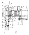
- the device for separating plate-shaped objects 30 has a magazine 31 which is equipped with a lifting device 32 for the plates 30.
- a removal device 34 is assigned to the upper end 33 of the magazine 31, which pushes out the top plate 30 of a plate stack 15 held in the magazine 31 and transfers it to a device 35 for feeding the removed plates 30 for further processing.
- the device 35 transfers the plates 30 removed to a linear conveyor 27.
- a horizontal conveyor 36 equipped with two transport chains 2 is provided for loading the magazine 31 with plate packs 3.
- the magazine 31 is formed by two groups of bars 4, 6 and 8 or 5, 7 and 9.
- Each of the rods 4 to 9 has a lifting member 14 at its upper end so that it can pivot, which has a downward-facing inclined surface 37 and on the top of which the plate stack 15 or a plate pack 3 rests.
- the rods 4, 6 and 8 of one group are connected to a plate 10 which can be raised or lowered by rotating a spindle 12.
- the rods 5, 7 and 9 of the second group are connected to a plate 11 which can be raised and lowered by rotating a spindle 13. In this way, the lifting members 14 of the group formed by the rods 4, 6, 8 can be raised or lowered independently of the lifting members 14 of the other group formed by the other rods 5, 7, 9.
- the removal device 34 at the upper end 33 of the magazine 31 has a push finger 19 which can be moved back and forth with a swivel arm 18, which in turn is coupled to a crank mechanism 16 via a rod 17 (arrow 38).
- the thrust finger 19 lies under its own weight on the uppermost plate 30 of the plate stack 15 and has at its front end a shoulder 39 which, during the removal stroke, on the edge of the uppermost plate 30 of the plate stack 15 facing the push finger 19 attacks.
- the removal device 34 also has a retaining device 40, which consists of a vertically guided feeler roller 28 and a retaining bar 29 connected to it.
- the feeler roller 28 rests on the top of the uppermost plate 30 of the plate stack 15 in the magazine 31.
- the retaining bar 29 is connected to the guide bar 41 for the sensing roller 28 so that there is a distance between the lower horizontal tangent to the sensing roller 28 and the upper edge of the retaining bar 29, which is slightly smaller than the thickness of two plates.
- the feeler roller 28 and the retaining bar 29, seen transversely to the image plane of FIG. 1, are narrow.
- the device 35 for feeding plates 30 removed from the magazine 31 to the side has a pair of transport rollers 20 which are provided directly next to the upper end 33 of the plate stack 15 and are driven in rotation in the direction of the arrows 42 and the plates 30 removed by the pushing finger 19 are free of one conveyed rotatable or driven support roller 21 supported.
- the plates 30 conveyed on by the transport rollers 20 are gripped by suction heads 23 and moved further in the direction of the arrow 43.
- the suction heads 23 are fastened in groups of four to an endless conveyor member 22, which is designed, for example, as a belt-shaped toothed belt. Bores 44 extend from the cavity of the suction heads 23 and extend through the toothed belt 22.
- four groups of four suction heads 23 are provided on the toothed belt 22.
- a vacuum chamber 24 is provided within the toothed belt 22 and is open towards the toothed belt 22 and the latter Edges are sealed against the toothed belt 22.
- the suction heads 23 are subjected to negative pressure through the bores 44 as long as the mouths of the bores 44 are in the region of the vacuum chamber.
- a plate-shaped object 30 is thus gripped when it has been moved into the region 45 by the transport rollers 20.
- a pair of overpressure chambers 25 are provided in the vacuum chamber 24, which are arranged at a distance from one another corresponding to the distance between the suction heads 23 and the bores 44.
- the pressure chamber 25 which has the shape of elongated nozzles, the suction heads 23 are subjected to overpressure in the region 46, so that the plate 30 held up to that point by the suction heads 23 is placed on the linear conveyor 27.
- Plate packs 3 are placed on the transport chains 2 of the horizontal conveyor 36 by hand or with the aid of a robot.
- the plate packs 3 are gradually fed to the lower end of the magazine 31.
- a supplied plate pack 3 is detected and raised by a group of the lifting devices, which are formed by the bars 5, 7, 9 or 4, 6, 8 and the lifting members 14, the plate pack 3 via its bottom plate 30 to three Lifting members 14 rests.
- a plate pack 3 is gripped by the lifting members 14 on the rods 5, 7 and 9, whereas the lifting members 14 on the rods 4, 6 and 8 the plate stack 15 in the removal position at the upper end 33 of the magazine Hold 31.
- the plate 11 with the rods 5, 7 and 9 is raised by rotating the spindle 13 and in the course of the upward movement of the plate package 3, the lifting members 14 at the ends of the rods 4, 6 and 8 on the uppermost plate 30 are pressed outwards, so that the plate pack 3 becomes part of the plate stack 15 by connecting to it at the bottom.
- the spindle 13 now takes over the upper edge control, in the meantime the rods 4, 6 and 8 can be lowered in order to receive a plate pack 3, which has in the meantime been pushed in by the horizontal conveyor 36, from the horizontal conveyor 6 or its conveyor chains 2 to take off.
- the loose thrust finger 19 resting on the plate stack 15 from above adapts, since it can be freely pivoted, to the small differences in height between the stroke switching impulses and inaccurate plates 30.
- a short stroke of the pushing finger 19 is sufficient to push the uppermost plate 30 for further transport between the pair of rollers 20, the retaining strip 29 preventing the plate 30 underneath from slipping due to friction or gluing between the plates.
- the retaining strip 29 is rigidly connected to the sensing roller 28, which rests on the plate stack 15 from above via its guide 41, it makes the small vertical movements of the plate stack 15 and the slot between the retaining strip 29 and the sensing roller 28 always remains the same and is always oriented correctly with respect to the top plate 30.
- the retaining bar 29 is advantageously narrow and arranged exactly under the feeler roller 28. This allows unavoidable irregularities caused by the plate production (bulged and thrown plates) must be compensated for, since the position of the slot between the retaining strip 29 and the feeler roller 28 can always adapt to the measured point of the respective situation.
- the pair of rollers 20 pushes out the separated plate 30 at the speed at which the suction heads 23 move in the direction of the arrow 43.
- the plate 30 is taken over by the suction heads 23 while the plate is being transported by the pair of rollers 20 as soon as the suction heads 23 reach the area of the vacuum chamber 24.
- the plate 30 is ejected in an exactly aligned manner through the pressure chambers 25 or pressure lines or compressed air nozzles and can be fed to the further processing with the linear conveyor 27.
Landscapes
- Engineering & Computer Science (AREA)
- Manufacturing & Machinery (AREA)
- Chemical & Material Sciences (AREA)
- Chemical Kinetics & Catalysis (AREA)
- Electrochemistry (AREA)
- General Chemical & Material Sciences (AREA)
- Sheets, Magazines, And Separation Thereof (AREA)
Priority Applications (2)
| Application Number | Priority Date | Filing Date | Title |
|---|---|---|---|
| AT90890064T ATE93206T1 (de) | 1990-03-07 | 1990-03-07 | Vorrichtung zum vereinzeln von plattenfoermigen gegenstaenden, insbesondere akkumulatorplatten. |
| DE9090890064T DE59002395D1 (de) | 1990-03-07 | 1990-03-07 | Vorrichtung zum vereinzeln von plattenfoermigen gegenstaenden, insbesondere akkumulatorplatten. |
Applications Claiming Priority (1)
| Application Number | Priority Date | Filing Date | Title |
|---|---|---|---|
| AT462/89A AT392858B (de) | 1989-03-01 | 1989-03-01 | Vorrichtung zum vereinzeln von plattenfoermigen gegenstaenden, insbesondere akkumulatorplatten |
Publications (2)
| Publication Number | Publication Date |
|---|---|
| EP0445496A1 true EP0445496A1 (fr) | 1991-09-11 |
| EP0445496B1 EP0445496B1 (fr) | 1993-08-18 |
Family
ID=3491269
Family Applications (1)
| Application Number | Title | Priority Date | Filing Date |
|---|---|---|---|
| EP90890064A Expired - Lifetime EP0445496B1 (fr) | 1989-03-01 | 1990-03-07 | Dispositif séparateur pour objects en forme de plaques, notamment plaques d'accumulateur |
Country Status (2)
| Country | Link |
|---|---|
| EP (1) | EP0445496B1 (fr) |
| AT (1) | AT392858B (fr) |
Cited By (14)
| Publication number | Priority date | Publication date | Assignee | Title |
|---|---|---|---|---|
| DE19529913A1 (de) * | 1995-08-15 | 1997-02-20 | Spintex Ag | Verfahren und Vorrichtung zum Lagern und Zuführen von Taschenfederschlangen |
| WO2006005089A1 (fr) * | 2004-07-12 | 2006-01-19 | Bm-Battery Machines Gmbh | Dispositif pour separer des articles sous forme de plaques, notamment des plaques de batterie |
| EP2106377A1 (fr) | 2007-01-04 | 2009-10-07 | BM-Battery Machines GmbH | Dispositif pour séparer des articles sous forme de plaques |
| DE102010019998A1 (de) * | 2010-05-10 | 2011-11-10 | Thermo Electron Led Gmbh | Objekthandhabungssystem zum Zuführen von Objekten zu einem Inkubator |
| DE102012218990A1 (de) * | 2012-10-18 | 2014-04-24 | Bundesdruckerei Gmbh | Vorrichtung und Verfahren zum Vereinzeln von einen Stapel bildenden Nutzenbögen |
| DE102013102454A1 (de) | 2013-03-12 | 2014-09-18 | Krones Aktiengesellschaft | Verfahren und Vorrichtung zur Vereinzelung von auf einem Stapel bereitgestellten Zwischenlagen |
| CN108526971A (zh) * | 2018-03-15 | 2018-09-14 | 陈善兰 | 一种板材用自动化上料机 |
| CN109720885A (zh) * | 2018-12-07 | 2019-05-07 | 成都信息工程大学 | 一种拼装式泡棉拆垛与信息喷印设备 |
| CN110329777A (zh) * | 2019-06-21 | 2019-10-15 | 广州蓝海智能装备有限公司 | 一种片材上料机及上料方法 |
| CN114348612A (zh) * | 2021-12-31 | 2022-04-15 | 苏州富强科技有限公司 | 交替升降式料仓组件 |
| CN114368510A (zh) * | 2021-12-31 | 2022-04-19 | 苏州富强科技有限公司 | 箱体成型及隔板入箱装置 |
| CN115180418A (zh) * | 2022-08-16 | 2022-10-14 | 广东华工环源环保科技有限公司 | 一种带自动计数分离压紧的蛋托堆叠机 |
| CN115231201A (zh) * | 2022-08-09 | 2022-10-25 | 安徽碳华新材料科技有限公司 | 一种用于超宽afg材料制备的运输传送装置 |
| CN116853799A (zh) * | 2023-08-16 | 2023-10-10 | 中科开创(广州)智能科技发展有限公司 | 一种用于地线修补夹片的送料机构和设备 |
Families Citing this family (1)
| Publication number | Priority date | Publication date | Assignee | Title |
|---|---|---|---|---|
| CN108249144A (zh) * | 2018-03-28 | 2018-07-06 | 广东广中皇食品有限公司 | 包装物卸垛设备 |
Citations (4)
| Publication number | Priority date | Publication date | Assignee | Title |
|---|---|---|---|---|
| GB949881A (en) * | 1961-10-12 | 1964-02-19 | Weybridge Machine Tool Company | Improvements in or relating to sheet feeding mechanisms |
| GB1101715A (en) * | 1964-02-18 | 1968-01-31 | Cotterell & Pither Ltd | Improvements in sheet feeding |
| GB2092117A (en) * | 1981-02-04 | 1982-08-11 | Mac Eng & Equip | Apparatus for transferring battery plates from one location to another |
| DE3150159A1 (de) * | 1981-03-13 | 1982-09-30 | VEB Kombinat Umformtechnik "Herbert Warnke" Erfurt, DDR 5010 Erfurt | "einrichtung zum transport und zur zufuehrung von blechstreifenstapeln" |
Family Cites Families (2)
| Publication number | Priority date | Publication date | Assignee | Title |
|---|---|---|---|---|
| US2568246A (en) * | 1949-01-08 | 1951-09-18 | Gen Motors Corp | Stack elevator control mechanism for collating machines |
| DE2709558C3 (de) * | 1977-03-04 | 1980-08-07 | Ivan Aleksandrovitsch Kolosov | Vorrichtung zur stückweisen Ausgabe von Elektroden für Akkumulatoren |
-
1989
- 1989-03-01 AT AT462/89A patent/AT392858B/de not_active IP Right Cessation
-
1990
- 1990-03-07 EP EP90890064A patent/EP0445496B1/fr not_active Expired - Lifetime
Patent Citations (4)
| Publication number | Priority date | Publication date | Assignee | Title |
|---|---|---|---|---|
| GB949881A (en) * | 1961-10-12 | 1964-02-19 | Weybridge Machine Tool Company | Improvements in or relating to sheet feeding mechanisms |
| GB1101715A (en) * | 1964-02-18 | 1968-01-31 | Cotterell & Pither Ltd | Improvements in sheet feeding |
| GB2092117A (en) * | 1981-02-04 | 1982-08-11 | Mac Eng & Equip | Apparatus for transferring battery plates from one location to another |
| DE3150159A1 (de) * | 1981-03-13 | 1982-09-30 | VEB Kombinat Umformtechnik "Herbert Warnke" Erfurt, DDR 5010 Erfurt | "einrichtung zum transport und zur zufuehrung von blechstreifenstapeln" |
Non-Patent Citations (1)
| Title |
|---|
| PATENT ABSTRACTS OF JAPAN vol. 13, no. 226 (E-763)(3574) 25 Mai 1989, & JP-A-1 035869 (YUASA BATTERY CO.) 06 Februar 1989, * |
Cited By (20)
| Publication number | Priority date | Publication date | Assignee | Title |
|---|---|---|---|---|
| DE19529913A1 (de) * | 1995-08-15 | 1997-02-20 | Spintex Ag | Verfahren und Vorrichtung zum Lagern und Zuführen von Taschenfederschlangen |
| WO2006005089A1 (fr) * | 2004-07-12 | 2006-01-19 | Bm-Battery Machines Gmbh | Dispositif pour separer des articles sous forme de plaques, notamment des plaques de batterie |
| US7690884B2 (en) * | 2004-07-12 | 2010-04-06 | Anton Schwetz | Finger and disk for separating plate-shaped objects, particularly battery plates |
| CN101010245B (zh) * | 2004-07-12 | 2010-07-07 | Bm-电池机械有限公司 | 用来分离板状物品,特别是蓄电池板的装置 |
| EP2106377A1 (fr) | 2007-01-04 | 2009-10-07 | BM-Battery Machines GmbH | Dispositif pour séparer des articles sous forme de plaques |
| DE102010019998A1 (de) * | 2010-05-10 | 2011-11-10 | Thermo Electron Led Gmbh | Objekthandhabungssystem zum Zuführen von Objekten zu einem Inkubator |
| DE102012218990A1 (de) * | 2012-10-18 | 2014-04-24 | Bundesdruckerei Gmbh | Vorrichtung und Verfahren zum Vereinzeln von einen Stapel bildenden Nutzenbögen |
| DE102012218990B4 (de) * | 2012-10-18 | 2017-10-19 | Bundesdruckerei Gmbh | Vorrichtung zum Vereinzeln von einen Stapel bildenden Nutzenbögen |
| DE102013102454A1 (de) | 2013-03-12 | 2014-09-18 | Krones Aktiengesellschaft | Verfahren und Vorrichtung zur Vereinzelung von auf einem Stapel bereitgestellten Zwischenlagen |
| CN108526971B (zh) * | 2018-03-15 | 2020-06-30 | 万金芬 | 一种板材用自动化上料机 |
| CN108526971A (zh) * | 2018-03-15 | 2018-09-14 | 陈善兰 | 一种板材用自动化上料机 |
| CN109720885A (zh) * | 2018-12-07 | 2019-05-07 | 成都信息工程大学 | 一种拼装式泡棉拆垛与信息喷印设备 |
| CN109720885B (zh) * | 2018-12-07 | 2020-12-22 | 成都信息工程大学 | 一种拼装式泡棉拆垛与信息喷印设备 |
| CN110329777A (zh) * | 2019-06-21 | 2019-10-15 | 广州蓝海智能装备有限公司 | 一种片材上料机及上料方法 |
| CN114348612A (zh) * | 2021-12-31 | 2022-04-15 | 苏州富强科技有限公司 | 交替升降式料仓组件 |
| CN114368510A (zh) * | 2021-12-31 | 2022-04-19 | 苏州富强科技有限公司 | 箱体成型及隔板入箱装置 |
| CN114348612B (zh) * | 2021-12-31 | 2023-07-04 | 苏州富强科技有限公司 | 交替升降式料仓组件 |
| CN115231201A (zh) * | 2022-08-09 | 2022-10-25 | 安徽碳华新材料科技有限公司 | 一种用于超宽afg材料制备的运输传送装置 |
| CN115180418A (zh) * | 2022-08-16 | 2022-10-14 | 广东华工环源环保科技有限公司 | 一种带自动计数分离压紧的蛋托堆叠机 |
| CN116853799A (zh) * | 2023-08-16 | 2023-10-10 | 中科开创(广州)智能科技发展有限公司 | 一种用于地线修补夹片的送料机构和设备 |
Also Published As
| Publication number | Publication date |
|---|---|
| EP0445496B1 (fr) | 1993-08-18 |
| ATA46289A (de) | 1990-11-15 |
| AT392858B (de) | 1991-06-25 |
Similar Documents
| Publication | Publication Date | Title |
|---|---|---|
| AT392858B (de) | Vorrichtung zum vereinzeln von plattenfoermigen gegenstaenden, insbesondere akkumulatorplatten | |
| EP1765703B1 (fr) | Dispositif pour separer des articles sous forme de plaques, notamment des plaques de batterie | |
| DE3506360C2 (fr) | ||
| CH671566A5 (fr) | ||
| DE4142162A1 (de) | Verfahren zum be- und entladen von paletten mit stapeln von flaechigen produkten und vorrichtung zur durchfuehrung des verfahrens | |
| EP0336332A2 (fr) | Dispositif pour prendre, empiler et désempiler et transporter des feuilles de verre | |
| EP2106377B1 (fr) | Dispositif pour séparer des articles sous forme de plaques | |
| DE3405432C2 (fr) | ||
| DE3028151A1 (de) | Vorrichtung zum entstapeln von flachen einheiten von verpackungsmaterial | |
| EP1044151B1 (fr) | Dispositif pour prelever des objets sous forme de plaques | |
| DE2537268C3 (de) | Vorrichtung zum Entnehmen von Behältern aus Kästen | |
| DE3414996C1 (de) | Vorrichtung zum Abschieben von auf einer Trageinrichtung abgelegten Stapeln oder Paketen | |
| EP1604923A1 (fr) | Procédé et dispositif pour l'empilement et le transfert de plaques | |
| DE2004334C3 (de) | Vorrichtung zum Stapeln von nacheinander zuzuführenden Bogen | |
| DE2838580C2 (fr) | ||
| DE19618344A1 (de) | Vorrichtung zum Handhaben von Zuschnittstapeln | |
| EP0471661B1 (fr) | Dispositif pour l'assemblage de plaques et de séparateurs en blocs de plaques pour accumulateurs | |
| EP1389597B1 (fr) | Méthode et dispositif pour dépiler une pile d'articles disposés en plusieurs couches horizontales | |
| EP2243731B1 (fr) | Dispositif de palettisation d'articles par couches | |
| DE2938688A1 (de) | Entstapler | |
| DE3309525C2 (fr) | ||
| DE4426615C1 (de) | Vorrichtung zum Stapeln oder Entstapeln von stapelbarem Gut | |
| DE3203757A1 (de) | Vorrichtung zum zwischenstapeln von gegenstaenden | |
| DE2549264A1 (de) | Vorrichtung zum vereinzeln von gestapelten ventilsaecken und verfahren zur stapelung derartiger saecke | |
| EP0210172B1 (fr) | Dispositif pour empiler des pieces a paroi mince |
Legal Events
| Date | Code | Title | Description |
|---|---|---|---|
| PUAI | Public reference made under article 153(3) epc to a published international application that has entered the european phase |
Free format text: ORIGINAL CODE: 0009012 |
|
| AK | Designated contracting states |
Kind code of ref document: A1 Designated state(s): AT DE FR GB IT |
|
| GBC | Gb: translation of claims filed (gb section 78(7)/1977) | ||
| EL | Fr: translation of claims filed | ||
| 17P | Request for examination filed |
Effective date: 19920304 |
|
| 17Q | First examination report despatched |
Effective date: 19921016 |
|
| GRAA | (expected) grant |
Free format text: ORIGINAL CODE: 0009210 |
|
| AK | Designated contracting states |
Kind code of ref document: B1 Designated state(s): AT DE FR GB IT |
|
| REF | Corresponds to: |
Ref document number: 93206 Country of ref document: AT Date of ref document: 19930915 Kind code of ref document: T |
|
| GBT | Gb: translation of ep patent filed (gb section 77(6)(a)/1977) |
Effective date: 19930817 |
|
| REF | Corresponds to: |
Ref document number: 59002395 Country of ref document: DE Date of ref document: 19930923 |
|
| ET | Fr: translation filed | ||
| ITF | It: translation for a ep patent filed |
Owner name: DR. ING. A. RACHELI & C |
|
| PLBE | No opposition filed within time limit |
Free format text: ORIGINAL CODE: 0009261 |
|
| STAA | Information on the status of an ep patent application or granted ep patent |
Free format text: STATUS: NO OPPOSITION FILED WITHIN TIME LIMIT |
|
| 26N | No opposition filed | ||
| PGFP | Annual fee paid to national office [announced via postgrant information from national office to epo] |
Ref country code: FR Payment date: 19960220 Year of fee payment: 7 |
|
| PGFP | Annual fee paid to national office [announced via postgrant information from national office to epo] |
Ref country code: GB Payment date: 19960306 Year of fee payment: 7 |
|
| PGFP | Annual fee paid to national office [announced via postgrant information from national office to epo] |
Ref country code: AT Payment date: 19960328 Year of fee payment: 7 |
|
| PGFP | Annual fee paid to national office [announced via postgrant information from national office to epo] |
Ref country code: DE Payment date: 19960506 Year of fee payment: 7 |
|
| PG25 | Lapsed in a contracting state [announced via postgrant information from national office to epo] |
Ref country code: GB Effective date: 19970307 Ref country code: AT Effective date: 19970307 |
|
| GBPC | Gb: european patent ceased through non-payment of renewal fee |
Effective date: 19970307 |
|
| PG25 | Lapsed in a contracting state [announced via postgrant information from national office to epo] |
Ref country code: FR Free format text: LAPSE BECAUSE OF NON-PAYMENT OF DUE FEES Effective date: 19971128 |
|
| PG25 | Lapsed in a contracting state [announced via postgrant information from national office to epo] |
Ref country code: DE Effective date: 19971202 |
|
| REG | Reference to a national code |
Ref country code: FR Ref legal event code: ST |
|
| PG25 | Lapsed in a contracting state [announced via postgrant information from national office to epo] |
Ref country code: IT Free format text: LAPSE BECAUSE OF NON-PAYMENT OF DUE FEES;WARNING: LAPSES OF ITALIAN PATENTS WITH EFFECTIVE DATE BEFORE 2007 MAY HAVE OCCURRED AT ANY TIME BEFORE 2007. THE CORRECT EFFECTIVE DATE MAY BE DIFFERENT FROM THE ONE RECORDED. Effective date: 20050307 |