EP0445496A1 - Separating device for platelike articles, in particular accumulator plates - Google Patents
Separating device for platelike articles, in particular accumulator plates Download PDFInfo
- Publication number
- EP0445496A1 EP0445496A1 EP90890064A EP90890064A EP0445496A1 EP 0445496 A1 EP0445496 A1 EP 0445496A1 EP 90890064 A EP90890064 A EP 90890064A EP 90890064 A EP90890064 A EP 90890064A EP 0445496 A1 EP0445496 A1 EP 0445496A1
- Authority
- EP
- European Patent Office
- Prior art keywords
- plate
- plates
- magazine
- suction heads
- lifting members
- Prior art date
- Legal status (The legal status is an assumption and is not a legal conclusion. Google has not performed a legal analysis and makes no representation as to the accuracy of the status listed.)
- Granted
Links
Images

Classifications
-
- H—ELECTRICITY
- H01—ELECTRIC ELEMENTS
- H01M—PROCESSES OR MEANS, e.g. BATTERIES, FOR THE DIRECT CONVERSION OF CHEMICAL ENERGY INTO ELECTRICAL ENERGY
- H01M10/00—Secondary cells; Manufacture thereof
- H01M10/04—Construction or manufacture in general
- H01M10/0404—Machines for assembling batteries
-
- B—PERFORMING OPERATIONS; TRANSPORTING
- B65—CONVEYING; PACKING; STORING; HANDLING THIN OR FILAMENTARY MATERIAL
- B65G—TRANSPORT OR STORAGE DEVICES, e.g. CONVEYORS FOR LOADING OR TIPPING, SHOP CONVEYOR SYSTEMS OR PNEUMATIC TUBE CONVEYORS
- B65G59/00—De-stacking of articles
- B65G59/02—De-stacking from the top of the stack
- B65G59/04—De-stacking from the top of the stack by suction or magnetic devices
- B65G59/045—De-stacking from the top of the stack by suction or magnetic devices with a stepwise upward movement of the stack
-
- H—ELECTRICITY
- H01—ELECTRIC ELEMENTS
- H01M—PROCESSES OR MEANS, e.g. BATTERIES, FOR THE DIRECT CONVERSION OF CHEMICAL ENERGY INTO ELECTRICAL ENERGY
- H01M10/00—Secondary cells; Manufacture thereof
- H01M10/06—Lead-acid accumulators
- H01M10/12—Construction or manufacture
- H01M10/14—Assembling a group of electrodes or separators
-
- Y—GENERAL TAGGING OF NEW TECHNOLOGICAL DEVELOPMENTS; GENERAL TAGGING OF CROSS-SECTIONAL TECHNOLOGIES SPANNING OVER SEVERAL SECTIONS OF THE IPC; TECHNICAL SUBJECTS COVERED BY FORMER USPC CROSS-REFERENCE ART COLLECTIONS [XRACs] AND DIGESTS
- Y02—TECHNOLOGIES OR APPLICATIONS FOR MITIGATION OR ADAPTATION AGAINST CLIMATE CHANGE
- Y02E—REDUCTION OF GREENHOUSE GAS [GHG] EMISSIONS, RELATED TO ENERGY GENERATION, TRANSMISSION OR DISTRIBUTION
- Y02E60/00—Enabling technologies; Technologies with a potential or indirect contribution to GHG emissions mitigation
- Y02E60/10—Energy storage using batteries
-
- Y—GENERAL TAGGING OF NEW TECHNOLOGICAL DEVELOPMENTS; GENERAL TAGGING OF CROSS-SECTIONAL TECHNOLOGIES SPANNING OVER SEVERAL SECTIONS OF THE IPC; TECHNICAL SUBJECTS COVERED BY FORMER USPC CROSS-REFERENCE ART COLLECTIONS [XRACs] AND DIGESTS
- Y02—TECHNOLOGIES OR APPLICATIONS FOR MITIGATION OR ADAPTATION AGAINST CLIMATE CHANGE
- Y02P—CLIMATE CHANGE MITIGATION TECHNOLOGIES IN THE PRODUCTION OR PROCESSING OF GOODS
- Y02P70/00—Climate change mitigation technologies in the production process for final industrial or consumer products
- Y02P70/50—Manufacturing or production processes characterised by the final manufactured product
Definitions
- the invention relates to a device for separating plate-shaped objects, in particular accumulator plates, with a magazine in which the plates to be separated are stacked one above the other.
- magazines have been proposed for accommodating plate-shaped objects, in particular accumulator plates.
- the purpose of these magazines is to keep a stack of plate-shaped objects ready, from which plates can be removed individually.
- AT-PS 379 786 describes a device for separating plates from stacks, which works with two suction heads which can be moved back and forth by a common drive and which alternately pick up and deposit individual plates from plate stacks provided on both sides of a conveying device.
- a similar device is known from DE-OS 21 48 532.
- the invention has for its object to provide a device for separating plate-shaped objects of the type mentioned with the soft, easily deformable and dimensional tolerances having plate-shaped objects, such as accumulator plates, can be reliably and reliably separated.
- the magazine is assigned a lifting device for the plates, which raises the plates fed to the magazine from below in the magazine upwards to a removal point, and in that a removal device is assigned to the upper end of the magazine, which the each top plate of the plate stack contained in the magazine is individually pushed out of the magazine and transferred to a device for feeding the removed plates for further processing.
- the plates can be fed to the magazine in the form of packages of plates and removed individually at the upper end of the magazine. By removing from the upper end, the weight of the stack of plates does not adversely affect the removal process.
- the lifting device has at least two lifting members which are actuated independently of one another. Due to the arrangement of independently operable lifting elements, plate packs can be pushed from below at the top of the magazine without obstruction and interference with the removal process.
- the lifting members are mounted so that they can be pivoted outwards, then when a plate pack is pushed in, they are pivoted outward from the top plate in each case, so that the stack of plates in the magazine are carried by the lifting members that have pushed the next plate pack in, and the lifting members, which previously held the uppermost plate pack, can be moved down and made available for feeding a further plate pack.
- This pivoting of the lifting members takes place particularly easily if the lifting members have downward-facing inclined surfaces on which the top plate of a subsequent plate pack engages in order to press the lifting members outwards.
- the lifting members are arranged on bars which are equipped with actuating devices which are independent of one another. It can be provided according to the invention that two spindle drives are provided as actuating devices.
- a particularly favorable arrangement results, if there are three bars arranged side by side on both sides of the magazine, two outer bars on one side and the middle bar on the opposite side of the magazine belonging to a group of lifting members.
- each plate pack is held in the magazine by three lifting members, so that no tilting of the plate is to be feared even when a plate stack is transferred.
- a particularly fast-working embodiment of the invention results if the removal device has at least one thrust finger which can be pushed back and forth essentially in the plane of the top plate. It can be provided that the thrust finger is moved back and forth by a crank mechanism. It is also preferred if the thrust finger is articulated to a swivel arm which is coupled to the crank mechanism via a rod and rests under its own weight on the top plate, and that the thrust finger has a shoulder at its front end over which it engages attacks the plate to be removed. As a result, the thrust finger adjusts itself correctly to the top plate.
- the design of the removal device with the pushing finger according to the invention and the pressure of the same preferred according to the invention ensure a particularly rapid removal of individual plates from the plate stack.
- An advantageous embodiment of the invention is characterized in that a stop is provided as a retaining device for the second plate seen from above, which is guided in the device such that it can be moved up and down or pivoted and with a feeler roller which rests on the top of the top plate , connected is.
- a stop is provided as a retaining device for the second plate seen from above, which is guided in the device such that it can be moved up and down or pivoted and with a feeler roller which rests on the top of the top plate , connected is.
- no actual guide edges which limit the interior of the magazine need to be provided, since the plate following the plate to be removed, ie the second uppermost one Plate, is held by the retaining device so that only the top plate is pushed out laterally by the removal device with the thrust finger.
- the arrangement of the feeler roller automatically adjusts to the correct position. It is preferred that the distance between the lower horizontal tangent to the feeler roller and the upper edge of the retaining strip is smaller than the thickness of two plates lying one on top of
- the feeler roller and the retaining bar are essentially of the same width.
- the retaining strip can be arranged narrowly and exactly under the roller and irregularities caused by the plate production, in particular in the case of accumulator plates, such as bulged or thrown plates, are compensated for, since the gap between the sensing roller and the Align the retaining bar precisely and the top plate can be pushed out between the feeler roller and the retaining bar during the removal process.
- the device for supplying removed plates for further processing has transport rollers acting on the plates from both sides next to the upper end of the magazine and suction heads movable in the removal plane.
- a simple embodiment of the invention is characterized in that the suction heads are attached to an endlessly rotating conveyor member. It can advantageously be provided that suction heads combined in groups act on a plate. This embodiment does not require a reciprocating mechanism for the vacuum cups, so that the removal speed is further increased is possible.
- a vacuum chamber is assigned to the conveyor belt to which the suction heads are attached, in the area in which they accommodate plates, and in that the suction heads are conveyed to the vacuum chamber by the conveying member stay in contact.
- a vacuum chamber is assigned to the discharge point for the plate gripped by the suction heads and that the suction heads are connected to the pressure chamber of the conveying member.
- the vacuum chamber extends over the entire area, in which suction heads hold plates, that the at least one pressure chamber is arranged within the vacuum chamber and that the edges of the downwardly open chambers facing the conveying member seal against the conveying member are.
- the transfer of removed plates to the suction heads is particularly safe if a drivable support roller is provided for the plates between the area in which the suction heads grip plates and the transport rollers.
- a further embodiment of the invention is characterized in that a horizontal conveyor is provided for loading the magazine with plate packs. It will usually be provided that the delivery point of the horizontal conveyor is in the area of the lifting links.
- a particularly advantageous control of the device according to the invention is obtained if a sensor detecting the presence of a plate is provided at the upper end of the magazine, which controls the drive for the lifting elements in such a way that, after a plate has been removed from the plate stack by the removal device, the uppermost one Lifting plates holding the plate stack are raised further by a step corresponding to a plate thickness, so that the top plate is in the removal position.
- the feeding of the separated plates for further processing takes place within the scope of the invention in that a linear conveyor for separated plates is provided below the delivery point of the device for feeding plates for further processing.
- the device for separating plate-shaped objects 30 has a magazine 31 which is equipped with a lifting device 32 for the plates 30.
- a removal device 34 is assigned to the upper end 33 of the magazine 31, which pushes out the top plate 30 of a plate stack 15 held in the magazine 31 and transfers it to a device 35 for feeding the removed plates 30 for further processing.
- the device 35 transfers the plates 30 removed to a linear conveyor 27.
- a horizontal conveyor 36 equipped with two transport chains 2 is provided for loading the magazine 31 with plate packs 3.
- the magazine 31 is formed by two groups of bars 4, 6 and 8 or 5, 7 and 9.
- Each of the rods 4 to 9 has a lifting member 14 at its upper end so that it can pivot, which has a downward-facing inclined surface 37 and on the top of which the plate stack 15 or a plate pack 3 rests.
- the rods 4, 6 and 8 of one group are connected to a plate 10 which can be raised or lowered by rotating a spindle 12.
- the rods 5, 7 and 9 of the second group are connected to a plate 11 which can be raised and lowered by rotating a spindle 13. In this way, the lifting members 14 of the group formed by the rods 4, 6, 8 can be raised or lowered independently of the lifting members 14 of the other group formed by the other rods 5, 7, 9.
- the removal device 34 at the upper end 33 of the magazine 31 has a push finger 19 which can be moved back and forth with a swivel arm 18, which in turn is coupled to a crank mechanism 16 via a rod 17 (arrow 38).
- the thrust finger 19 lies under its own weight on the uppermost plate 30 of the plate stack 15 and has at its front end a shoulder 39 which, during the removal stroke, on the edge of the uppermost plate 30 of the plate stack 15 facing the push finger 19 attacks.
- the removal device 34 also has a retaining device 40, which consists of a vertically guided feeler roller 28 and a retaining bar 29 connected to it.
- the feeler roller 28 rests on the top of the uppermost plate 30 of the plate stack 15 in the magazine 31.
- the retaining bar 29 is connected to the guide bar 41 for the sensing roller 28 so that there is a distance between the lower horizontal tangent to the sensing roller 28 and the upper edge of the retaining bar 29, which is slightly smaller than the thickness of two plates.
- the feeler roller 28 and the retaining bar 29, seen transversely to the image plane of FIG. 1, are narrow.
- the device 35 for feeding plates 30 removed from the magazine 31 to the side has a pair of transport rollers 20 which are provided directly next to the upper end 33 of the plate stack 15 and are driven in rotation in the direction of the arrows 42 and the plates 30 removed by the pushing finger 19 are free of one conveyed rotatable or driven support roller 21 supported.
- the plates 30 conveyed on by the transport rollers 20 are gripped by suction heads 23 and moved further in the direction of the arrow 43.
- the suction heads 23 are fastened in groups of four to an endless conveyor member 22, which is designed, for example, as a belt-shaped toothed belt. Bores 44 extend from the cavity of the suction heads 23 and extend through the toothed belt 22.
- four groups of four suction heads 23 are provided on the toothed belt 22.
- a vacuum chamber 24 is provided within the toothed belt 22 and is open towards the toothed belt 22 and the latter Edges are sealed against the toothed belt 22.
- the suction heads 23 are subjected to negative pressure through the bores 44 as long as the mouths of the bores 44 are in the region of the vacuum chamber.
- a plate-shaped object 30 is thus gripped when it has been moved into the region 45 by the transport rollers 20.
- a pair of overpressure chambers 25 are provided in the vacuum chamber 24, which are arranged at a distance from one another corresponding to the distance between the suction heads 23 and the bores 44.
- the pressure chamber 25 which has the shape of elongated nozzles, the suction heads 23 are subjected to overpressure in the region 46, so that the plate 30 held up to that point by the suction heads 23 is placed on the linear conveyor 27.
- Plate packs 3 are placed on the transport chains 2 of the horizontal conveyor 36 by hand or with the aid of a robot.
- the plate packs 3 are gradually fed to the lower end of the magazine 31.
- a supplied plate pack 3 is detected and raised by a group of the lifting devices, which are formed by the bars 5, 7, 9 or 4, 6, 8 and the lifting members 14, the plate pack 3 via its bottom plate 30 to three Lifting members 14 rests.
- a plate pack 3 is gripped by the lifting members 14 on the rods 5, 7 and 9, whereas the lifting members 14 on the rods 4, 6 and 8 the plate stack 15 in the removal position at the upper end 33 of the magazine Hold 31.
- the plate 11 with the rods 5, 7 and 9 is raised by rotating the spindle 13 and in the course of the upward movement of the plate package 3, the lifting members 14 at the ends of the rods 4, 6 and 8 on the uppermost plate 30 are pressed outwards, so that the plate pack 3 becomes part of the plate stack 15 by connecting to it at the bottom.
- the spindle 13 now takes over the upper edge control, in the meantime the rods 4, 6 and 8 can be lowered in order to receive a plate pack 3, which has in the meantime been pushed in by the horizontal conveyor 36, from the horizontal conveyor 6 or its conveyor chains 2 to take off.
- the loose thrust finger 19 resting on the plate stack 15 from above adapts, since it can be freely pivoted, to the small differences in height between the stroke switching impulses and inaccurate plates 30.
- a short stroke of the pushing finger 19 is sufficient to push the uppermost plate 30 for further transport between the pair of rollers 20, the retaining strip 29 preventing the plate 30 underneath from slipping due to friction or gluing between the plates.
- the retaining strip 29 is rigidly connected to the sensing roller 28, which rests on the plate stack 15 from above via its guide 41, it makes the small vertical movements of the plate stack 15 and the slot between the retaining strip 29 and the sensing roller 28 always remains the same and is always oriented correctly with respect to the top plate 30.
- the retaining bar 29 is advantageously narrow and arranged exactly under the feeler roller 28. This allows unavoidable irregularities caused by the plate production (bulged and thrown plates) must be compensated for, since the position of the slot between the retaining strip 29 and the feeler roller 28 can always adapt to the measured point of the respective situation.
- the pair of rollers 20 pushes out the separated plate 30 at the speed at which the suction heads 23 move in the direction of the arrow 43.
- the plate 30 is taken over by the suction heads 23 while the plate is being transported by the pair of rollers 20 as soon as the suction heads 23 reach the area of the vacuum chamber 24.
- the plate 30 is ejected in an exactly aligned manner through the pressure chambers 25 or pressure lines or compressed air nozzles and can be fed to the further processing with the linear conveyor 27.
Landscapes
- Engineering & Computer Science (AREA)
- Manufacturing & Machinery (AREA)
- Chemical & Material Sciences (AREA)
- Chemical Kinetics & Catalysis (AREA)
- Electrochemistry (AREA)
- General Chemical & Material Sciences (AREA)
- Sheets, Magazines, And Separation Thereof (AREA)
Abstract
Description
Die Erfindung betrifft eine Vorrichtung zum Vereinzeln von plattenförmigen Gegenständen, insbesondere von Akkumulatorplatten mit einem Magazin, in dem die zu vereinzelnden Platten übereinandergestapelt sind.The invention relates to a device for separating plate-shaped objects, in particular accumulator plates, with a magazine in which the plates to be separated are stacked one above the other.
Zur Aufnahme plattenförmiger Gegenstände, insbesondere Akkumulatorenplatten, sind die verschiedensten Ausführungsformen von Magazinen vorgeschlagen worden. Zweck dieser Magazine ist es, einen Stapel plattenförmiger Gegenstände bereit zu halten, dem Platten einzeln entnommen werden können.The most diverse embodiments of magazines have been proposed for accommodating plate-shaped objects, in particular accumulator plates. The purpose of these magazines is to keep a stack of plate-shaped objects ready, from which plates can be removed individually.
Neben Vertikalmagazinen, wie sie aus der DE-OS 23 08 946, der DE-PS 10 82 950, der AT-PS 241 565, der AT-PS 329 124 und der AT-PS 352 197 bekannt sind und bei welchen die plattenförmigen Gegenstände am unteren Ende des Magazins entnommen werden, sind auch andere Ausführungsformen von Magazinen bekannt. So beschreibt die AT-PS 379 786 eine Vorrichtung zum Vereinzeln von Platten aus Stapeln, die mit zwei durch einen gemeinsamen Antrieb hin- und herbewegbaren Saugköpfen arbeitet, welche abwechselnd von auf beiden Seiten einer Fördervorrichtung vorgesehenen Plattenstapeln vereinzelte Platten aufnehmen und ablegen. Eine ähnliche Vorrichtung ist aus der DE-OS 21 48 532 bekannt.In addition to vertical magazines, as are known from DE-OS 23 08 946, DE-PS 10 82 950, AT-PS 241 565, AT-PS 329 124 and AT-PS 352 197, and in which the plate-shaped objects are removed at the lower end of the magazine, other embodiments of magazines are known. For example, AT-PS 379 786 describes a device for separating plates from stacks, which works with two suction heads which can be moved back and forth by a common drive and which alternately pick up and deposit individual plates from plate stacks provided on both sides of a conveying device. A similar device is known from DE-OS 21 48 532.
Aus der DE-PS 935 374 ist eine mit Vakuumsaugern ausgestattete Vorrichtung zum Zusammenbau von Plattensätzen für Akkumulatoren bekannt.From DE-PS 935 374 a device equipped with vacuum suction devices for assembling plate sets for accumulators is known.
Aus der EP-B-141 806 ist ein Horizontalmagazin für plattenförmige Gegenstände bekannt, dem ein mit einem Vakuumsaugkopf ausgestatteter Greifer einzeln Platten von der Vorderseite des im Horizontalmagazin aufgenommenen Stapels nebeneinanderstehender plattenförmiger Gegenstände entnimmt. Hiezu sind besondere Rückhaltevorrichtungen notwendig, damit der Saugkopf durch seine Saugwirkung nicht mehr als eine Platte entnimmt.From EP-B-141 806 a horizontal magazine for plate-shaped objects is known, to which a gripper equipped with a vacuum suction head individually plates from the front of the stack of adjacent plate-shaped objects accommodated in the horizontal magazine takes. Special retention devices are required for this so that the suction head does not remove more than one plate due to its suction effect.
Die bekannten Vorrichtungen zum Vereinzeln von plattenförmigen Gegenständen aus Plattenstapeln arbeiten vergleichsweise langsam, so daß sie für schnell arbeitende Vorrichtungen zum Zusammenbauen von Akkumulatorenplattenstapeln oder für schnell arbeitenden Vorrichtungen zum Einhüllen von Akkumulatorenplatten in Separatoren ("Eintaschmaschinen") nicht hinreichen. Bei modernen Eintaschmaschinen werden Leistungen von über 100 Akkumulatorenplatten pro Minute gefordert. Diese Leistungen können die herkömmlichen Vereinzelungsvorrichtungen (auch Plattenleger genannt) nicht erreichen. Ein besonderes Problem ergibt sich beim Vereinzeln von Akkumulatorenplatten, da diese aus Blei bestehen und daher weich und leicht verformbar sind und überdies große Abmessungstoleranzen haben.The known devices for separating plate-like objects from plate stacks work comparatively slowly, so that they are not sufficient for fast-working devices for assembling accumulator plate stacks or for fast-working devices for wrapping accumulator plates in separators ("pocket machines"). In modern pocket machines, outputs of over 100 battery plates per minute are required. The conventional separating devices (also called plate layers) cannot achieve this performance. A particular problem arises when separating accumulator plates, since these consist of lead and are therefore soft and easily deformable and moreover have large dimensional tolerances.
Der Erfindung liegt die Aufgabe zugrunde, eine Vorrichtung zum Vereinzeln von plattenförmigen Gegenständen der eingangs genannten Gattung anzugeben mit der auch weiche, leicht verformbare und Abmessungstoleranzen aufweisende plattenförmige Gegenstände, wie Akkumulatorenplatten, mit hoher Leistung und zuverlässig vereinzelt werden können.The invention has for its object to provide a device for separating plate-shaped objects of the type mentioned with the soft, easily deformable and dimensional tolerances having plate-shaped objects, such as accumulator plates, can be reliably and reliably separated.
Gelöst wird diese Aufgabe gemäß der Erfindung dadurch, daß dem Magazin eine Hebeeinrichtung für die Platten zugeordnet ist, welche die dem Magazin von unten zugeführten Platten im Magazin nach oben zu einer Entnahmestelle anhebt und daß dem oberen Ende des Magazins eine Entnahmevorrichtung zugeordnet ist, welche die jeweils oberste Platte des im Magazin enthaltenen Plattenstapels einzeln aus dem Magazin ausschiebt und an eine Vorrichtung zum Zuführen der entnommenen Platten zur weiteren Bearbeitung übergibt.This object is achieved according to the invention in that the magazine is assigned a lifting device for the plates, which raises the plates fed to the magazine from below in the magazine upwards to a removal point, and in that a removal device is assigned to the upper end of the magazine, which the each top plate of the plate stack contained in the magazine is individually pushed out of the magazine and transferred to a device for feeding the removed plates for further processing.
Aufgrund der Konstruktion der erfindungsgemäßen Vorrichtung können die Platten dem Magazin in Form von Paketen aus Platten zugeführt und am oberen Ende des Magazins einzeln entnommen werden. Durch die Entnahme vom oberen Ende wirkt sich das Gewicht des Plattenstapels nicht nachteilig auf den Entnahmevorgang aus.Due to the construction of the device according to the invention, the plates can be fed to the magazine in the form of packages of plates and removed individually at the upper end of the magazine. By removing from the upper end, the weight of the stack of plates does not adversely affect the removal process.
In einer Ausführungsform der Erfindung ist vorgesehen, daß die Hebevorrichtung wenigstens zwei voneinander unabhängig betätigte Hebeglieder aufweist. Durch die Anordnung von unabhängig betätigbaren Hebegliedern können Plattenpakete ohne Behinderung und Störung des Entnahmevorganges am oberen Ende des Magazins von unten her nachgeschoben werden.In one embodiment of the invention it is provided that the lifting device has at least two lifting members which are actuated independently of one another. Due to the arrangement of independently operable lifting elements, plate packs can be pushed from below at the top of the magazine without obstruction and interference with the removal process.
Wenn gemäß einer Ausführungsform der Erfindung die Hebeglieder nach außen verschwenkbar gelagert sind, dann werden sie beim Nachschieben eines Plattenpaketes von der jeweils obersten Platte desselben nach außen verschwenkt, so daß die Plattenstapel im Magazin von den Hebegliedern getragen werden, die das nächste Plattenpaket nachgeschoben haben, und die Hebeglieder, welche zuvor das oberste Plattenpaket hielten, nach unten bewegt und zur Zuführung eines weiteren Plattenpaketes bereit gestellt werden können. Dieses Verschwenken der Hebenglieder erfolgt besonders problemlos, wenn die Hebeglieder nach unten weisende Schrägflächen aufweisen, an welchen die jeweils oberste Platte eines nachfolgenden Plattenpaketes angreift, um die Hebeglieder nach außen zu drücken.If, according to one embodiment of the invention, the lifting members are mounted so that they can be pivoted outwards, then when a plate pack is pushed in, they are pivoted outward from the top plate in each case, so that the stack of plates in the magazine are carried by the lifting members that have pushed the next plate pack in, and the lifting members, which previously held the uppermost plate pack, can be moved down and made available for feeding a further plate pack. This pivoting of the lifting members takes place particularly easily if the lifting members have downward-facing inclined surfaces on which the top plate of a subsequent plate pack engages in order to press the lifting members outwards.
In einer praktischen Ausführungsform der Erfindung ist vorgesehen, daß die Hebeglieder an Stäben angeordnet sind, die mit voneinander unabhängigen Betätigungsvorrichtungen ausgestattet sind. Dabei kann erfindungsgemäß vorgesehen sein, daß als Betätigungsvorrichtungen zwei Spindeltriebe vorgesehen sind.In a practical embodiment of the invention it is provided that the lifting members are arranged on bars which are equipped with actuating devices which are independent of one another. It can be provided according to the invention that two spindle drives are provided as actuating devices.
Eine räumlich besonders günstige Anordnung ergibt sich, wenn auf beiden Seiten des Magazins je drei nebeneinander angeordnete Stäbe vorgesehen sind, wobei jeweils zwei äußere Stäbe auf einer Seite und der mittlere Stab auf der gegenüberliegenden Seite des Magazins zu einer Gruppe von Hebegliedern gehört. Bei dieser Ausführungsform wird jedes Plattenpaket im Magazin von drei Hebegliedern gehalten, so daß auch beim Übergeben eines Plattenstapels keine Verkantungen desselben zu befürchten sind.A particularly favorable arrangement results, if there are three bars arranged side by side on both sides of the magazine, two outer bars on one side and the middle bar on the opposite side of the magazine belonging to a group of lifting members. In this embodiment, each plate pack is held in the magazine by three lifting members, so that no tilting of the plate is to be feared even when a plate stack is transferred.
Eine besonders rasch arbeitende Ausführungsform der Erfindung ergibt sich, wenn die Entnahmevorrichtung wenigstens einen Schubfinger aufweist, der im wesentlichen in der Ebene der obersten Platte vor- und zurückschiebbar ist. Dabei kann vorgesehen sein, daß der Schubfinger durch einen Kurbeltrieb hin- und herbewegt wird. Bevorzugt ist noch, wenn der Schubfinger mit einem Schwenkarm, der über eine Stange mit dem Kurbeltrieb gekuppelt ist, gelenkig verbunden ist und unter seinem Eigengewicht auf der obersten Platte aufliegt, und daß der Schubfinger an seinem vorderen Ende eine Schulter aufweist, über die er an der zu entnehmenden Platte angreift. Dadurch justiert sich der Schubfinger zur obersten Platte von selbst jeweils richtig aus. Die erfindungsgemäße Ausführung der Entnahmevorrichtung mit dem Schubfinger und der erfindungsgemäß bevorzugte Andruck desselben gewährleisten ein besonders rasches Entnehmen von einzelnen Platten aus dem Plattenstapel.A particularly fast-working embodiment of the invention results if the removal device has at least one thrust finger which can be pushed back and forth essentially in the plane of the top plate. It can be provided that the thrust finger is moved back and forth by a crank mechanism. It is also preferred if the thrust finger is articulated to a swivel arm which is coupled to the crank mechanism via a rod and rests under its own weight on the top plate, and that the thrust finger has a shoulder at its front end over which it engages attacks the plate to be removed. As a result, the thrust finger adjusts itself correctly to the top plate. The design of the removal device with the pushing finger according to the invention and the pressure of the same preferred according to the invention ensure a particularly rapid removal of individual plates from the plate stack.
Eine vorteilhafte Ausgestaltung der Erfindung ist dadurch gekennzeichnet, daß als Rückhaltevorrichtung für die von oben gesehen zweite Platte ein Anschlag vorgesehen ist, der in der Vorrichtung auf- und abverschiebbar geführt oder verschwenkbar gelagert ist und mit einer Tastrolle, die auf der Oberseite der obersten Platte anliegt, verbunden ist. Bei dieser Ausführungsform brauchen keine eigentlichen Führungskanten, die den Innenraum des Magazins begrenzen, vorgesehen sein, da die der zu entnehmenden Platte nachfolgende Platte, d.h. die zweitoberste Platte, von der Rückhaltevorrichtung gehalten wird, so daß nur die oberste Platte von der Entnahmevorrichtung mit dem Schubfinger seitlich ausgeschoben wird. Durch die Anordnung der Tastrolle stellt sich die Rückhaltevorrichtung automatisch jeweils auf die richtige Lage ein. Dabei ist bevorzugt, daß der Abstand zwischen der unteren horizontalen Tangente an die Tastrolle und der Oberkante der Rückhalteleiste kleiner ist als die Dicke von zwei aufeinanderliegenden Platten.An advantageous embodiment of the invention is characterized in that a stop is provided as a retaining device for the second plate seen from above, which is guided in the device such that it can be moved up and down or pivoted and with a feeler roller which rests on the top of the top plate , connected is. In this embodiment, no actual guide edges which limit the interior of the magazine need to be provided, since the plate following the plate to be removed, ie the second uppermost one Plate, is held by the retaining device so that only the top plate is pushed out laterally by the removal device with the thrust finger. The arrangement of the feeler roller automatically adjusts to the correct position. It is preferred that the distance between the lower horizontal tangent to the feeler roller and the upper edge of the retaining strip is smaller than the thickness of two plates lying one on top of the other.
Eine vorteilhafte Ausführungsform ergibt sich, wenn die Tastrolle und die Rückhalteleiste im wesentlichen gleich breit ausgebildet sind. Bei dieser Ausführungsform ergibt sich der Vorteil, daß die Rückhalteleiste schmal und genau unter der Rolle angeordnet sein kann und durch die Plattenproduktion, insbesondere bei Akkumulatorplatten bedingte Unregelmäßigkeiten, wie beispielsweise ausgebauchte oder geworfene Platten, ausgeglichen werden, da sich der Spalt zwischen der Tastrolle und der Rückhalteleiste genau ausrichten kann und die oberste Platte beim Entnahmevorgang zwischen Tastrolle und Rückhalteleiste ausgeschoben werden kann.An advantageous embodiment is obtained if the feeler roller and the retaining bar are essentially of the same width. In this embodiment, there is the advantage that the retaining strip can be arranged narrowly and exactly under the roller and irregularities caused by the plate production, in particular in the case of accumulator plates, such as bulged or thrown plates, are compensated for, since the gap between the sensing roller and the Align the retaining bar precisely and the top plate can be pushed out between the feeler roller and the retaining bar during the removal process.
Zur Unterstützung des Entnahmevorganges und zum Weiterbewegen der entnommenen Platten kann vorgesehen sein, daß die Vorrichtung zum Zuführen entnommener Platten zur weiteren Bearbeitung neben dem oberen Ende des Magazins von beiden Seiten an den Platten her angreifende Transportrollen und in der Entnahmeebene bewegliche Saugköpfe aufweist.To support the removal process and to move the removed plates, it can be provided that the device for supplying removed plates for further processing has transport rollers acting on the plates from both sides next to the upper end of the magazine and suction heads movable in the removal plane.
Eine einfache Ausführungsform der Erfindung kennzeichnet sich dadurch, daß die Saugköpfe an einem endlos umlaufenden Förderglied befestigt sind. Dabei kann mit Vorteil vorgesehen sein, daß jeweils zu Gruppen zusammengefaßte Saugköpfe an einer Platte angreifen. Diese Ausführungsform kommt ohne Hin- und Herbewegungsmechanismus für die Vakuumsauger aus, so daß eine weitere Steigerung der Entnahmegeschwindigkeit möglich ist.A simple embodiment of the invention is characterized in that the suction heads are attached to an endlessly rotating conveyor member. It can advantageously be provided that suction heads combined in groups act on a plate. This embodiment does not require a reciprocating mechanism for the vacuum cups, so that the removal speed is further increased is possible.
Die Beaufschlagung der Saugköpfe mit Unterdruck erfolgt im Rahmen der Erfindung mit Vorteil dadurch, daß dem Förderband, an dem die Saugköpfe befestigt sind, im Bereich, in dem sie Platten aufnehmen, eine Unterdruckkammer zugeordnet ist, und daß die Saugköpfe durch das Förderglied mit der Unterdruckkammer in Verbindung stehen. Zum Ablegen der Platten kann erfindungsgemäß vorgesehen sein, daß an der Abgabestelle für von den Saugköpfen erfaßte Platte eine Unterdruckkammer zugeordnet ist und daß die Saugköpfe mit der Überdruckkammer des Fördergliedes in Verbindung stehen. In einer praktischen Ausführungsform kann vorgesehen sein, daß sich die Unterdruckkammer über den gesamten Bereich erstreckt, in dem Saugköpfe Platten halten, daß die wenigstens eine Überdruckkammer innerhalb der Unterdruckkammer engeordnet ist und daß die dem Förderglied zugekehrten Ränder der nach unten offenen Kammern gegenüber dem Förderglied angedichtet sind.The application of vacuum to the suction heads is advantageously carried out in the context of the invention in that a vacuum chamber is assigned to the conveyor belt to which the suction heads are attached, in the area in which they accommodate plates, and in that the suction heads are conveyed to the vacuum chamber by the conveying member stay in contact. For storing the plates, it can be provided according to the invention that a vacuum chamber is assigned to the discharge point for the plate gripped by the suction heads and that the suction heads are connected to the pressure chamber of the conveying member. In a practical embodiment it can be provided that the vacuum chamber extends over the entire area, in which suction heads hold plates, that the at least one pressure chamber is arranged within the vacuum chamber and that the edges of the downwardly open chambers facing the conveying member seal against the conveying member are.
Die Übergabe von entnommenen Platten auf die Saugköpfe gestaltet sich besonders sicher, wenn zwischen dem Bereich, in dem die Saugköpfe Platten erfassen und den Transportrollen eine antreibbare Stützrolle für die Platten vorgesehen ist.The transfer of removed plates to the suction heads is particularly safe if a drivable support roller is provided for the plates between the area in which the suction heads grip plates and the transport rollers.
Eine weitere Ausgestaltung der Erfindung ist dadurch gekennzeichnet, daß zum Beschicken des Magazins mit Plattenpaketen ein Horizontalförderer vorgesehen ist. Dabei wird für gewöhnlich vorgesehen sein, daß die Abgabestelle des Horizontalförderers im Bereich der Hebeglieder liegt.A further embodiment of the invention is characterized in that a horizontal conveyor is provided for loading the magazine with plate packs. It will usually be provided that the delivery point of the horizontal conveyor is in the area of the lifting links.
Eine besonders vorteilhafte Steuerung der erfindungsgemäßen Vorrichtung ergibt sich, wenn am oberen Ende des Magazins ein die Anwesenheit einer Platte erfassender Sensor vorgesehen ist, der den Antrieb für die Hebeglieder so steuert, daß nach der Entnahme einer Platte vom Plattenstapel durch die Entnahmevorrichtung die den obersten Plattenstapel haltenden Hebeglieder um einen einer Plattenstärke entsprechenden Schritt weiter angehoben werden, so daß die jeweils oberste Platte in der Entnahmeposition ist.A particularly advantageous control of the device according to the invention is obtained if a sensor detecting the presence of a plate is provided at the upper end of the magazine, which controls the drive for the lifting elements in such a way that, after a plate has been removed from the plate stack by the removal device, the uppermost one Lifting plates holding the plate stack are raised further by a step corresponding to a plate thickness, so that the top plate is in the removal position.
Das Zuführen der vereinzelten Platten zur weiteren Bearbeitung erfolgt im Rahmen der Erfindugn mit Vorteil dadurch, daß unterhalb der Abgabestelle der Vorrichtung zum Zuführen von Platten zur weiteren Bearbeitung ein Linearförderer für vereinzelte Platten vorgesehen ist.The feeding of the separated plates for further processing takes place within the scope of the invention in that a linear conveyor for separated plates is provided below the delivery point of the device for feeding plates for further processing.
Weitere Einzelheiten und Merkmale der Erfindung ergeben sich aus der nachstehenden Beschreibung der in der Zeichnung teils schematisch wiedergegebenen Ausführungsform.
Es zeigt:
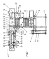
- Fig. 1 eine Vereinzelungsvorrichtung in Seitenansicht bzw. im Schnitt längs der Linie C-D in Fig. 2 und
- Fig. 2 die Vorrichtung aus Fig. 1 in Draufsicht bzw. im Schnitt längs der Linie A-B in Fig. 1.
It shows:
- Fig. 1 shows a separating device in side view or in section along the line CD in Fig. 2 and
- 2 shows the device from FIG. 1 in plan view or in section along the line AB in FIG. 1.
Die Vorrichtung zum Vereinzeln von plattenförmigen Gegenständen 30 weist ein Magazin 31 auf, das mit einer Hebeeinrichtung 32 für die Platten 30 ausgerüstet ist. Dem oberen Ende 33 des Magazins 31 ist eine Entnahmevorrichtung 34 zugeordnet, welche die jeweils oberste Platte 30 eines im Magazin 31 gehaltenen Plattenstapels 15 seitlich ausschiebt und an eine Vorrichtung 35 zum Zuführen der entnommenen Platten 30 zur weiteren Bearbeitung übergibt. Die Vorrichtung 35 übergibt im gezeigten Ausführungsbeispiel die entnommenen Platten 30 auf einen Linearförderer 27.The device for separating plate-
Zum Beschicken des Magazins 31 mit Plattenpaketen 3 ist ein mit zwei Transportketten 2 ausgestatteter Horizontalförderer 36 vorgesehen.A
Das Magazin 31 wird von zwei Gruppen von Stäben 4, 6 und 8 bzw. 5, 7 und 9 gebildet. Jeder der Stäbe 4 bis 9 trägt an seinem oberen Ende verschwenkbar gelagert ein Hebeglied 14, das eine nach unten weisende Schrägfläche 37 besitzt und auf dessen Oberseite der Plattenstapel 15 bzw. ein Plattenpaket 3 aufliegt.The
Um die Hebeglieder 14 anheben zu können, sind die Stäbe 4, 6 und 8 der einen Gruppe mit einer Platte 10 verbunden, die durch Verdrehen einer Spindel 12 angehoben bzw. abgesenkt werden kann.In order to be able to lift the lifting members 14, the
Die Stäbe 5, 7 und 9 der zweiten Gruppe sind mit einer Platte 11 verbunden, die durch Verdrehen einer Spindel 13 angehoben und abgesenkt werden kann. Auf diese Weise können die Hebeglieder 14 der von den Stäben 4, 6, 8 gebildeten Gruppe unabhängig von den Hebegliedern 14 der anderen von den anderen Stäben 5, 7, 9 gebildeten Gruppe angehoben bzw. abgesenkt werden.The
Aus Fig. 2 ist noch ersichtlich, daß die Stäbe 4 bis 9 jeder der zwei Gruppen in den Eckpunkten eines Dreieckes angeordnet sind, wobei jeweils drei Stäbe 4, 5, 6 auf der einen und drei Stäbe 7, 8, 9 auf der anderen von zwei einander gegenüberliegenden Seiten des Magazins 31 vorgesehen sind. Dabei gehören die beiden äußeren Stäbe der einen Seite und der mittlere Stab auf der gegenüberliegenden Seite jeweils zu einer Gruppe.From Fig. 2 it can still be seen that the
Die Entnahmevorrichtung 34 am oberen Ende 33 des Magazins 31 weist einen Schubfinger 19 auf, der mit einem Schwenkarm 18, der seinerseits über eine Stange 17 mit einem Kurbeltrieb 16 gekuppelt ist, hin- und herbwegbar ist (Pfeil 38). Der Schubfinger 19 liegt unter seinem Eigengewicht auf der obersten Platte 30 des Plattenstapels 15 auf und besitzt an seinem vorderen Ende eine Schulter 39, die beim Entnahmehub an der dem Schubfinger 19 zugekehrten Kante der obersten Platte 30 des Plattenstapels 15 angreift.The
Die Entnahmevorrichtung 34 besitzt weiters eine Rückhalteeinrichtung 40, die aus einer vertikal geführten Tastrolle 28 und einer mit dieser verbundenen Rückhalteleiste 29 besteht. Die Tastrolle 28 liegt auf der Oberseite der jeweils obersten Platte 30 des Plattenstapels 15 im Magazin 31 auf. Die Rückhalteleiste 29 ist mit der Führungs-Leiste 41 für die Tastrolle 28 so verbunden, daß zwischen der unteren horizontalen Tangente an die Tastrolle 28 und der Oberkante der Rückhalteleiste 29 ein Abstand besteht, der etwas kleiner ist, als die Stärke zweier Platten. Weiters sind die Tastrolle 28 und die Rückhalteleiste 29, quer zur Bildebene der Fig. 1 gesehen, schmal ausgebildet.The
Die Vorrichtung 35 zum Zuführen dem Magazin 31 zur Seite hin entnommener Platten 30 besitzt ein unmittelbar neben dem oberen Ende 33 des Plattenstapels 15 vorgesehenes Paar Transportrollen 20, die in Richtung der Pfeile 42 drehangetrieben sind und die vom Schubfinger 19 entnommene Platten 30, von einer frei drehbaren oder angetriebenen Stützrolle 21 abgestützt weiterbefördern. Die von den Transportrollen 20 weiterbeförderten Platten 30 werden von Saugköpfen 23 erfaßt und in Richtung des Pfeiles 43 weiterbewegt.The
Die Saugköpfe 23 sind zu Gruppen zu jeweils vier an einem Endlosförderglied 22, das beispielsweise als bandförmiger Zahnriemen ausgebildet ist, befestigt. Vom Hohlraum der Saugköpfe 23 gehen Bohrungen 44 aus, die sich durch den Zahnriemen 22 erstrecken.The suction heads 23 are fastened in groups of four to an
Im gezeigten Ausführungsbeispiel sind am Zahnriemen 22 vier Gruppen zu je vier Saugköpfen 23 vorgesehen.In the exemplary embodiment shown, four groups of four suction heads 23 are provided on the
Innerhalb des Zahnriemens 22 ist eine Unterdruckkammer 24 vorgesehen, die zum Zahnriemen 22 hin offen ist und deren Ränder gegenüber dem Zahnriemen 22 angedichtet sind. Durch die Bohrungen 44 werden die Saugköpfe 23 mit Unterdruck beaufschlagt, solange sich die Mündungen der Bohrungen 44 im Bereich der Unterdruckkammer befinden. So wird ein plattenförmiger Gegenstand 30 ergriffen, wenn dieser von den Transportrollen 20 in den Bereich 45 bewegt worden ist.A
Im Bereich 46, d.h. oberhalb des Linearförderers 27, ist in der Unterdruckkammer 24 ein Paar von Überdruckkammern 25 vorgesehen, die voneinander in einem dem Abstand der Saugköpfe 23 bzw. der Bohrungen 44 voneinander entsprechenden Abstand angeordnet sind. Durch die Überdruckkammer 25, welche die Form von länglichen Düsen besitzt, werden die Saugköpfe 23 im Bereich 46 mit Überdruck beaufschlagt, so daß die bis dahin von den Saugköpfen 23 gehaltene Platte 30 auf den Linearförderer 27 abgelegt wird.In
Die soeben beschriebene Vorrichtung arbeitet wie folgt:
Plattenpakete 3 werden von Hand aus oder mit Hilfe eines Roboters auf die Transportketten 2 des Horizontalförderers 36 aufgelegt. Die Plattenpakete 3 werden schrittweise zum unteren Ende des Magazins 31 zugeführt. Dort wird ein zugeführtes Plattenpaket 3 von einer Gruppe der Hebeeinrichtungen, die von den Stäben 5, 7, 9 bzw. 4, 6, 8 und den Hebegliedern 14 gebildet werden, erfaßt und angehoben, wobei das Plattenpaket 3 über seine unterste Platte 30 auf drei Hebegliedern 14 aufliegt.The device just described works as follows:
Plate packs 3 are placed on the
In der in Fig. 1 gezeigten Phase wird ein Plattenpaket 3 von den Hebegliedern 14 an den Stangen 5, 7 und 9 erfaßt, wogegen die Hebeglieder 14 an den Stangen 4, 6 und 8 den Plattenstapel 15 in der Entnahmeposition am oberen Ende 33 des Magazins 31 halten.In the phase shown in Fig. 1, a
Nach Entnahme der obersten Platte 30 aus dem Plattenstapel 15 wird durch eine Oberkantensteuerung der Plattenstapel 15 durch Heben der Stäbe 4, 6 und 8 (bzw. wenn die andere Gruppe der Stäbe 5, 7 und 9 wirksam wird) wieder in die Entnahme- bzw. Ausschiebeposition angehoben.After removing the
Weiters wird die Platte 11 mit den Stäben 5, 7 und 9 durch Drehen der Spindel 13 angehoben und im Zuge der Aufwärtsbewegung des Plattenpaketes 3 werden die Hebeglieder 14 an den Enden der Stäbe 4, 6 und 8 an der obersten Platte 30 nach außen gedrückt, so daß das Plattenpaket 3 Teil des Plattenstapels 15 wird, indem es an diesen unten anschließt. Durch einen Schaltimpuls des Hebegliedes 14 auf dem Stab 8 übernimmt nun die Spindel 13 die Oberkantensteuerung, wobei in der Zwischenzeit die Stäbe 4, 6 und 8 abgesenkt werden können, um ein vom Horizontalförderer 36 zwischenzeitlich nachgeschobenes Plattenpaket 3 vom Horizontalförderer 6 bzw. dessen Förderketten 2 abzuheben.Furthermore, the
Der lose, auf dem Plattenstapel 15 von oben her aufliegende Schubfinger 19 paßt sich, da er frei verschwenkbar ist, den kleinen Höhenunterschieden zwischen den Hubschaltimpulsen und ungenauen Platten 30 an. Ein kurzer Hub des Schubfingers 19 genügt, um die oberste Platte 30 für den Weitertransport zwischen das Rollenpaar 20 zu schieben, wobei die Rückhalteleiste 29 das durch Reibung oder Klebung zwischen den Platten bewirkte Mitrutschen der darunter liegenden Platte 30 verhindert. Da die Rückhalteleiste 29 mit der Tastrolle 28, die auf dem Plattenstapel 15 von oben aufliegt über deren Führung 41 starr verbunden ist, macht sie die kleinen senkrechten Bewegungen des Plattenstapels 15 mit und der Schlitz zwischen der Rückhalteleiste 29 und der Tastrolle 28 bleibt immer gleich und orientiert sich immer richtig gegenüber der obersten Platte 30 aus.The
Mit Vorteil ist die Rückhalteleiste 29 schmal ausgebildet und genau unter der Tastrolle 28 angeordnet. Dadurch können durch die Plattenproduktion verursachte unvermeidliche Unregelmäßigkeiten (ausgebauchte und geworfene Platten) ausgeglichen werden, da sich die Lage des Schlitzes zwischen der Rückhalteleiste 29 und der Tastrolle 28 stets der gemessenen Stelle der jeweiligen Situation anpassen kann.The retaining
Das Rollenpaar 20 schiebt die vereinzelte Platte 30 mit der Geschwindigkeit aus, mit der sich die Saugköpfe 23 in Richtung des Pfeiles 43 bewegen. Dabei wird noch während des Plattentransportes durch das Rollenpaar 20 die Platte 30 von den Saugköpfen 23 übernommen, sobald die Saugköpfe 23 in den Bereich der Vakuumkammer 24 gelangen.The pair of
An der Abgabe- bzw. Abwurfstelle 46 wird durch die Überdruckkammern 25 bzw. Überdruckleitungen oder Druckluftdüsen die Platte 30 genau ausgerichtet abgeworfen und kann mit dem Linearförderer 27 der weiteren Verarbeitung zugeführt werden.At the delivery or
Claims (24)
Priority Applications (2)
| Application Number | Priority Date | Filing Date | Title |
|---|---|---|---|
| DE9090890064T DE59002395D1 (en) | 1990-03-07 | 1990-03-07 | DEVICE FOR SEPARATING PLATE-SHAPED OBJECTS, IN PARTICULAR ACCUMULATOR PLATES. |
| AT90890064T ATE93206T1 (en) | 1990-03-07 | 1990-03-07 | DEVICE FOR SEPARATING PLATE-FORM OBJECTS, ESPECIALLY ACCUMULATOR PLATES. |
Applications Claiming Priority (1)
| Application Number | Priority Date | Filing Date | Title |
|---|---|---|---|
| AT462/89A AT392858B (en) | 1989-03-01 | 1989-03-01 | DEVICE FOR SEPARATING PLATE-SHAPED OBJECTS, IN PARTICULAR ACCUMULATOR PLATES |
Publications (2)
| Publication Number | Publication Date |
|---|---|
| EP0445496A1 true EP0445496A1 (en) | 1991-09-11 |
| EP0445496B1 EP0445496B1 (en) | 1993-08-18 |
Family
ID=3491269
Family Applications (1)
| Application Number | Title | Priority Date | Filing Date |
|---|---|---|---|
| EP90890064A Expired - Lifetime EP0445496B1 (en) | 1989-03-01 | 1990-03-07 | Separating device for platelike articles, in particular accumulator plates |
Country Status (2)
| Country | Link |
|---|---|
| EP (1) | EP0445496B1 (en) |
| AT (1) | AT392858B (en) |
Cited By (14)
| Publication number | Priority date | Publication date | Assignee | Title |
|---|---|---|---|---|
| DE19529913A1 (en) * | 1995-08-15 | 1997-02-20 | Spintex Ag | System for storing and conveying strings of pocket springs for e.g. mattresses |
| WO2006005089A1 (en) * | 2004-07-12 | 2006-01-19 | Bm-Battery Machines Gmbh | Device for separating plate-shaped objects, particularly battery plates |
| EP2106377A1 (en) | 2007-01-04 | 2009-10-07 | BM-Battery Machines GmbH | Apparatus for separating plate-shaped objects |
| DE102010019998A1 (en) * | 2010-05-10 | 2011-11-10 | Thermo Electron Led Gmbh | Object handling system for isolating object i.e. microtiter plate, with or without lids before supplying to incubator in laboratory environment, has transportation system arranged under object to place object to transportation |
| DE102012218990A1 (en) * | 2012-10-18 | 2014-04-24 | Bundesdruckerei Gmbh | Separating device for separating polymer laminates that are utilized as pre-products of e.g. smart card, has displacement devices for displacing sheet in relation to other sheet such that former sheet is brought into projection |
| DE102013102454A1 (en) | 2013-03-12 | 2014-09-18 | Krones Aktiengesellschaft | Method and device for singling intermediate layers provided on a stack |
| CN108526971A (en) * | 2018-03-15 | 2018-09-14 | 陈善兰 | A kind of plank automation feeder |
| CN109720885A (en) * | 2018-12-07 | 2019-05-07 | 成都信息工程大学 | A kind of pin-connected panel foam de-stacking and information spray printing device |
| CN110329777A (en) * | 2019-06-21 | 2019-10-15 | 广州蓝海智能装备有限公司 | A kind of sheet material feeder and charging method |
| CN114348612A (en) * | 2021-12-31 | 2022-04-15 | 苏州富强科技有限公司 | Alternate lifting type stock bin assembly |
| CN114368510A (en) * | 2021-12-31 | 2022-04-19 | 苏州富强科技有限公司 | Box forming and partition board boxing device |
| CN115180418A (en) * | 2022-08-16 | 2022-10-14 | 广东华工环源环保科技有限公司 | Egg tray stacking machine with automatic counting, separating and pressing functions |
| CN115231201A (en) * | 2022-08-09 | 2022-10-25 | 安徽碳华新材料科技有限公司 | A transportation conveyer for super wide AFG material preparation |
| CN116853799A (en) * | 2023-08-16 | 2023-10-10 | 中科开创(广州)智能科技发展有限公司 | Feeding mechanism and equipment for ground wire repairing clamping piece |
Families Citing this family (1)
| Publication number | Priority date | Publication date | Assignee | Title |
|---|---|---|---|---|
| CN108249144A (en) * | 2018-03-28 | 2018-07-06 | 广东广中皇食品有限公司 | Packing material destacking equipment |
Citations (4)
| Publication number | Priority date | Publication date | Assignee | Title |
|---|---|---|---|---|
| GB949881A (en) * | 1961-10-12 | 1964-02-19 | Weybridge Machine Tool Company | Improvements in or relating to sheet feeding mechanisms |
| GB1101715A (en) * | 1964-02-18 | 1968-01-31 | Cotterell & Pither Ltd | Improvements in sheet feeding |
| GB2092117A (en) * | 1981-02-04 | 1982-08-11 | Mac Eng & Equip | Apparatus for transferring battery plates from one location to another |
| DE3150159A1 (en) * | 1981-03-13 | 1982-09-30 | VEB Kombinat Umformtechnik "Herbert Warnke" Erfurt, DDR 5010 Erfurt | Device for the transport and feeding of stacks of sheet-metal strips |
Family Cites Families (2)
| Publication number | Priority date | Publication date | Assignee | Title |
|---|---|---|---|---|
| US2568246A (en) * | 1949-01-08 | 1951-09-18 | Gen Motors Corp | Stack elevator control mechanism for collating machines |
| DE2709558C3 (en) * | 1977-03-04 | 1980-08-07 | Ivan Aleksandrovitsch Kolosov | Device for the piece-wise output of electrodes for accumulators |
-
1989
- 1989-03-01 AT AT462/89A patent/AT392858B/en not_active IP Right Cessation
-
1990
- 1990-03-07 EP EP90890064A patent/EP0445496B1/en not_active Expired - Lifetime
Patent Citations (4)
| Publication number | Priority date | Publication date | Assignee | Title |
|---|---|---|---|---|
| GB949881A (en) * | 1961-10-12 | 1964-02-19 | Weybridge Machine Tool Company | Improvements in or relating to sheet feeding mechanisms |
| GB1101715A (en) * | 1964-02-18 | 1968-01-31 | Cotterell & Pither Ltd | Improvements in sheet feeding |
| GB2092117A (en) * | 1981-02-04 | 1982-08-11 | Mac Eng & Equip | Apparatus for transferring battery plates from one location to another |
| DE3150159A1 (en) * | 1981-03-13 | 1982-09-30 | VEB Kombinat Umformtechnik "Herbert Warnke" Erfurt, DDR 5010 Erfurt | Device for the transport and feeding of stacks of sheet-metal strips |
Non-Patent Citations (1)
| Title |
|---|
| PATENT ABSTRACTS OF JAPAN vol. 13, no. 226 (E-763)(3574) 25 Mai 1989, & JP-A-1 035869 (YUASA BATTERY CO.) 06 Februar 1989, * |
Cited By (20)
| Publication number | Priority date | Publication date | Assignee | Title |
|---|---|---|---|---|
| DE19529913A1 (en) * | 1995-08-15 | 1997-02-20 | Spintex Ag | System for storing and conveying strings of pocket springs for e.g. mattresses |
| WO2006005089A1 (en) * | 2004-07-12 | 2006-01-19 | Bm-Battery Machines Gmbh | Device for separating plate-shaped objects, particularly battery plates |
| US7690884B2 (en) * | 2004-07-12 | 2010-04-06 | Anton Schwetz | Finger and disk for separating plate-shaped objects, particularly battery plates |
| CN101010245B (en) * | 2004-07-12 | 2010-07-07 | Bm-电池机械有限公司 | Device for removing plate-like objects, especially device of battery plate |
| EP2106377A1 (en) | 2007-01-04 | 2009-10-07 | BM-Battery Machines GmbH | Apparatus for separating plate-shaped objects |
| DE102010019998A1 (en) * | 2010-05-10 | 2011-11-10 | Thermo Electron Led Gmbh | Object handling system for isolating object i.e. microtiter plate, with or without lids before supplying to incubator in laboratory environment, has transportation system arranged under object to place object to transportation |
| DE102012218990A1 (en) * | 2012-10-18 | 2014-04-24 | Bundesdruckerei Gmbh | Separating device for separating polymer laminates that are utilized as pre-products of e.g. smart card, has displacement devices for displacing sheet in relation to other sheet such that former sheet is brought into projection |
| DE102012218990B4 (en) * | 2012-10-18 | 2017-10-19 | Bundesdruckerei Gmbh | Device for separating benefit sheets forming a stack |
| DE102013102454A1 (en) | 2013-03-12 | 2014-09-18 | Krones Aktiengesellschaft | Method and device for singling intermediate layers provided on a stack |
| CN108526971B (en) * | 2018-03-15 | 2020-06-30 | 万金芬 | Automatic feeding machine for plates |
| CN108526971A (en) * | 2018-03-15 | 2018-09-14 | 陈善兰 | A kind of plank automation feeder |
| CN109720885A (en) * | 2018-12-07 | 2019-05-07 | 成都信息工程大学 | A kind of pin-connected panel foam de-stacking and information spray printing device |
| CN109720885B (en) * | 2018-12-07 | 2020-12-22 | 成都信息工程大学 | Assembled foam unstacking and information jet printing equipment |
| CN110329777A (en) * | 2019-06-21 | 2019-10-15 | 广州蓝海智能装备有限公司 | A kind of sheet material feeder and charging method |
| CN114348612A (en) * | 2021-12-31 | 2022-04-15 | 苏州富强科技有限公司 | Alternate lifting type stock bin assembly |
| CN114368510A (en) * | 2021-12-31 | 2022-04-19 | 苏州富强科技有限公司 | Box forming and partition board boxing device |
| CN114348612B (en) * | 2021-12-31 | 2023-07-04 | 苏州富强科技有限公司 | Alternate lifting type stock bin assembly |
| CN115231201A (en) * | 2022-08-09 | 2022-10-25 | 安徽碳华新材料科技有限公司 | A transportation conveyer for super wide AFG material preparation |
| CN115180418A (en) * | 2022-08-16 | 2022-10-14 | 广东华工环源环保科技有限公司 | Egg tray stacking machine with automatic counting, separating and pressing functions |
| CN116853799A (en) * | 2023-08-16 | 2023-10-10 | 中科开创(广州)智能科技发展有限公司 | Feeding mechanism and equipment for ground wire repairing clamping piece |
Also Published As
| Publication number | Publication date |
|---|---|
| EP0445496B1 (en) | 1993-08-18 |
| ATA46289A (en) | 1990-11-15 |
| AT392858B (en) | 1991-06-25 |
Similar Documents
| Publication | Publication Date | Title |
|---|---|---|
| AT392858B (en) | DEVICE FOR SEPARATING PLATE-SHAPED OBJECTS, IN PARTICULAR ACCUMULATOR PLATES | |
| EP1765703B1 (en) | Device for separating plate-shaped objects, particularly battery plates | |
| DE3506360C2 (en) | ||
| CH671566A5 (en) | ||
| DE4142162A1 (en) | METHOD FOR LOADING AND UNLOADING PALLETS WITH STACKS OF FLAT PRODUCTS AND DEVICE FOR CARRYING OUT THE METHOD | |
| EP0336332A2 (en) | Apparatus for picking-up, stacking and destacking and transporting glass-panes | |
| EP2106377B1 (en) | Apparatus for separating plate-shaped objects | |
| DE3405432C2 (en) | ||
| DE3028151A1 (en) | DEVICE FOR DE-STACKING FLAT UNITS OF PACKAGING MATERIAL | |
| EP1044151B1 (en) | Device for removing plate-like objects | |
| DE2537268C3 (en) | Device for removing containers from boxes | |
| DE3414996C1 (en) | Device for pushing away stacks or packages deposited on a carrying device | |
| EP1604923A1 (en) | Device and method for stacking and transferring plates | |
| DE2004334C3 (en) | Device for stacking sheets to be fed one after the other | |
| DE2838580C2 (en) | ||
| DE19618344A1 (en) | Device for handling stacks of blanks | |
| EP0471661B1 (en) | Apparatus for assembling of plates and separators into plate groups for storage batteries | |
| EP1389597B1 (en) | Method and apparatus for destacking a stack of articles arranged in a plurality of horizontal layers | |
| EP2243731B1 (en) | Device for palletizing articles layer by layer | |
| DE2938688A1 (en) | STACKER | |
| DE3309525C2 (en) | ||
| DE4426615C1 (en) | Device to stack and unstack boxed and packaged goods | |
| DE3203757A1 (en) | Apparatus for the intermediate stacking of articles | |
| DE2549264A1 (en) | Equipment for lifting single sacks from stack - has suction heads for transferring sacks in vertical position on conveying equipment | |
| EP0210172B1 (en) | Device for stacking thin-walled parts |
Legal Events
| Date | Code | Title | Description |
|---|---|---|---|
| PUAI | Public reference made under article 153(3) epc to a published international application that has entered the european phase |
Free format text: ORIGINAL CODE: 0009012 |
|
| AK | Designated contracting states |
Kind code of ref document: A1 Designated state(s): AT DE FR GB IT |
|
| GBC | Gb: translation of claims filed (gb section 78(7)/1977) | ||
| EL | Fr: translation of claims filed | ||
| 17P | Request for examination filed |
Effective date: 19920304 |
|
| 17Q | First examination report despatched |
Effective date: 19921016 |
|
| GRAA | (expected) grant |
Free format text: ORIGINAL CODE: 0009210 |
|
| AK | Designated contracting states |
Kind code of ref document: B1 Designated state(s): AT DE FR GB IT |
|
| REF | Corresponds to: |
Ref document number: 93206 Country of ref document: AT Date of ref document: 19930915 Kind code of ref document: T |
|
| GBT | Gb: translation of ep patent filed (gb section 77(6)(a)/1977) |
Effective date: 19930817 |
|
| REF | Corresponds to: |
Ref document number: 59002395 Country of ref document: DE Date of ref document: 19930923 |
|
| ET | Fr: translation filed | ||
| ITF | It: translation for a ep patent filed |
Owner name: DR. ING. A. RACHELI & C |
|
| PLBE | No opposition filed within time limit |
Free format text: ORIGINAL CODE: 0009261 |
|
| STAA | Information on the status of an ep patent application or granted ep patent |
Free format text: STATUS: NO OPPOSITION FILED WITHIN TIME LIMIT |
|
| 26N | No opposition filed | ||
| PGFP | Annual fee paid to national office [announced via postgrant information from national office to epo] |
Ref country code: FR Payment date: 19960220 Year of fee payment: 7 |
|
| PGFP | Annual fee paid to national office [announced via postgrant information from national office to epo] |
Ref country code: GB Payment date: 19960306 Year of fee payment: 7 |
|
| PGFP | Annual fee paid to national office [announced via postgrant information from national office to epo] |
Ref country code: AT Payment date: 19960328 Year of fee payment: 7 |
|
| PGFP | Annual fee paid to national office [announced via postgrant information from national office to epo] |
Ref country code: DE Payment date: 19960506 Year of fee payment: 7 |
|
| PG25 | Lapsed in a contracting state [announced via postgrant information from national office to epo] |
Ref country code: GB Effective date: 19970307 Ref country code: AT Effective date: 19970307 |
|
| GBPC | Gb: european patent ceased through non-payment of renewal fee |
Effective date: 19970307 |
|
| PG25 | Lapsed in a contracting state [announced via postgrant information from national office to epo] |
Ref country code: FR Free format text: LAPSE BECAUSE OF NON-PAYMENT OF DUE FEES Effective date: 19971128 |
|
| PG25 | Lapsed in a contracting state [announced via postgrant information from national office to epo] |
Ref country code: DE Effective date: 19971202 |
|
| REG | Reference to a national code |
Ref country code: FR Ref legal event code: ST |
|
| PG25 | Lapsed in a contracting state [announced via postgrant information from national office to epo] |
Ref country code: IT Free format text: LAPSE BECAUSE OF NON-PAYMENT OF DUE FEES;WARNING: LAPSES OF ITALIAN PATENTS WITH EFFECTIVE DATE BEFORE 2007 MAY HAVE OCCURRED AT ANY TIME BEFORE 2007. THE CORRECT EFFECTIVE DATE MAY BE DIFFERENT FROM THE ONE RECORDED. Effective date: 20050307 |