EP2106377B1 - Apparatus for separating plate-shaped objects - Google Patents
Apparatus for separating plate-shaped objects Download PDFInfo
- Publication number
- EP2106377B1 EP2106377B1 EP07845280A EP07845280A EP2106377B1 EP 2106377 B1 EP2106377 B1 EP 2106377B1 EP 07845280 A EP07845280 A EP 07845280A EP 07845280 A EP07845280 A EP 07845280A EP 2106377 B1 EP2106377 B1 EP 2106377B1
- Authority
- EP
- European Patent Office
- Prior art keywords
- plate
- conveyor
- stack
- conveyor belt
- lifting
- Prior art date
- Legal status (The legal status is an assumption and is not a legal conclusion. Google has not performed a legal analysis and makes no representation as to the accuracy of the status listed.)
- Revoked
Links
Images


Classifications
-
- B—PERFORMING OPERATIONS; TRANSPORTING
- B65—CONVEYING; PACKING; STORING; HANDLING THIN OR FILAMENTARY MATERIAL
- B65G—TRANSPORT OR STORAGE DEVICES, e.g. CONVEYORS FOR LOADING OR TIPPING, SHOP CONVEYOR SYSTEMS OR PNEUMATIC TUBE CONVEYORS
- B65G59/00—De-stacking of articles
- B65G59/02—De-stacking from the top of the stack
- B65G59/04—De-stacking from the top of the stack by suction or magnetic devices
- B65G59/045—De-stacking from the top of the stack by suction or magnetic devices with a stepwise upward movement of the stack
-
- B—PERFORMING OPERATIONS; TRANSPORTING
- B65—CONVEYING; PACKING; STORING; HANDLING THIN OR FILAMENTARY MATERIAL
- B65G—TRANSPORT OR STORAGE DEVICES, e.g. CONVEYORS FOR LOADING OR TIPPING, SHOP CONVEYOR SYSTEMS OR PNEUMATIC TUBE CONVEYORS
- B65G2201/00—Indexing codes relating to handling devices, e.g. conveyors, characterised by the type of product or load being conveyed or handled
- B65G2201/02—Articles
- B65G2201/0214—Articles of special size, shape or weigh
- B65G2201/022—Flat
Landscapes
- Sheets, Magazines, And Separation Thereof (AREA)
- Mechanical Treatment Of Semiconductor (AREA)
- Secondary Cells (AREA)
- Stacking Of Articles And Auxiliary Devices (AREA)
- De-Stacking Of Articles (AREA)
- Intermediate Stations On Conveyors (AREA)
- Processing And Handling Of Plastics And Other Materials For Molding In General (AREA)
- Automobile Manufacture Line, Endless Track Vehicle, Trailer (AREA)
Abstract
Description
Die Erfindung betrifft eine Vorrichtung mit den Merkmalen des einleitenden Teils von Anspruch 1 (vgl.
Vorrichtungen zum Vereinzeln plattenförmiger Gegenstände, insbesondere von Batterie- oder Akkumulatorplatten, aus Stapeln plattenförmiger Gegenstände sind bekannt.Devices for separating plate-shaped objects, in particular of battery or Akkumulatorplatten, from stacking plate-shaped objects are known.
In älteren Vorschlägen für Vorrichtungen zum Entnehmen von Batterieplatten aus Stapeln von Batterieplatten (vgl.
Es sind daher auch schon Vorrichtungen vorgeschlagen worden, in welchen den Batterieplatten einer Entnahmestelle im wesentlichen lotrecht stehend, in horizontal ausgerichteten Stapeln zugeführt werden.Therefore, devices have already been proposed in which the battery plates of a removal point are substantially vertically standing, fed in horizontally aligned stacks.
Beispielhaft wird auf die
Nachteilig bei diesen bekannten Vorrichtungen ist es, dass sie wegen der komplizierten Bewegungen der Entnahmegreifer, welche die Platten einzeln aus horizontalen Stapeln entnehmen sollen, hinsichtlich ihrer Leistungsfähigkeit begrenzt sind.A disadvantage of these known devices is that they are limited in terms of their performance because of the complicated movements of the removal gripper, which should remove the plates individually from horizontal stacks.
Bekannt sind auch Vorrichtungen zum Vereinzeln plattenförmiger Gegenstände, insbesondere Batterie- oder Akkumulatorplatten, bei welchen die plattenförmigen Gegenstände horizontal ausgerichtet sind, und bei welchen die Gegenstände von oben aus dem Stapel entfernt werden.
Vorrichtungen dieser Bauart sind aus der
Devices of this type are from the
Dabei arbeiten Vorrichtungen, die aus der
In der
Mit der in der
Alle bekannten Vorrichtungen, insbesondere die der
Der Erfindung liegt die Aufgabe zu Grunde, eine Vorrichtung der eingangs genannten Gattung anzugeben, mit welcher beim Entnehmen von plattenförmigen Gegenständen, insbesondere (Blei-)Platten für Batterien und Akkumulatoren, aus Stapeln kürzere Taktzeiten möglich sind.The invention is based on the object to provide a device of the type mentioned, with which when removing plate-shaped objects, in particular (lead) plates for batteries and accumulators, shorter cycle times are possible from stacks.
Gelöst wird diese Aufgabe erfindungsgemäß mit einer Vorrichtung, welche die Merkmale von Anspruch 1 aufweist.This object is achieved according to the invention with a device having the features of claim 1.
Bevorzugte und vorteilhafte Ausgestaltungen der Erfindung sind Gegenstand der Unteransprüche.Preferred and advantageous embodiments of the invention are the subject of the dependent claims.
Da bei der erfindungsgemäßen Vorrichtung der jeweils oberste plattenförmige Gegenstand aus einem Stapel im wesentlichen horizontal liegender, plattenförmiger Gegenstände, welcher Stapel im wesentlichen lotrecht ausgerichtet ist, entnommen wird, ist eine einfache Bewegung des Entnahmegreifers ("Plattenleger") möglich. Dadurch können beim Vereinzeln von plattenförmigen Gegenständen aus Stapeln solcher plattenförmiger Gegenstände und beim Übergeben der vereinzelten plattenförmigen Gegenständen an Fördereinrichtungen kurze Taktzeiten erzielt werden.Since, in the device according to the invention, the respectively uppermost plate-shaped object is taken from a stack of substantially horizontally lying, plate-shaped objects, which stack is oriented essentially vertically, a simple movement of the removal gripper ("plate-laying") is possible. As a result, short cycle times can be achieved when separating plate-shaped objects from stacks of such plate-shaped objects and when transferring the separated plate-shaped objects to conveyors.
In einer bevorzugten Ausführungsform ist der als Entnahmegreifer vorgesehene Plattenleger als Förderband ausgebildet, an dem zwei oder mehrere Gruppen von Saugern vorgesehen sind, die zum Aufnehmen von plattenförmigen Gegenständen mit Unterdruck beaufschlagt sind und so lange mit Unterdruck beaufschlagt bleiben, bis die plattenförmigen Gegenstände an einen nachgeschalteten Förderer abgegeben werden.In a preferred embodiment, the plate gripper provided as a removal gripper is designed as a conveyor belt, on which two or more groups of suckers are provided, which are subjected to negative pressure for receiving plate-shaped objects and remain under negative pressure until the plate-shaped objects are connected to a downstream one Sponsors are delivered.
Insbesondere ist die erfindungsgemäße Vorrichtung für das Vereinzeln von in Stapeln herangeförderten Batterie- oder Akkumulatorplatten geeignet, wobei die vereinzelten Platten dann einer weiteren Bearbeitung, beispielsweise dem Bürsten der Kontaktfahnen, und Vorrichtungen zum Eintaschen von Batterie- oder Akkumulatorplatten zugeführt werden können.In particular, the device according to the invention is suitable for the separation of battery or accumulator plates conveyed in stacks, the separated plates then being able to be supplied for further processing, for example the brushing of the contact lugs, and devices for pocketing battery or accumulator plates.
Weitere Einzelheiten, Merkmale und Vorteile der erfindungsgemäßen Vorrichtung ergeben sich aus der nachstehenden Beschreibung eines bevorzugten Ausführungsbeispiels anhand der Zeichnungen. Es zeigt:
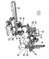
Plattenstapel 10 (Höhe von 4" bis 6") werden auf einem Horizontalförderer 20 (vorzugsweise eine Kettenfördereinrichtung) manuell oder automatisch positioniert. Auf dem Horizontalförderer 20 sind in der Teilung der Stapelabstände beispielsweise pneumatisch betriebene Aushebeeinheiten 21 positioniert, welche Plattenstapel 10 vom Horizontalförderer 20 abheben können. Somit ist gewährleistet, dass auf jedem Teilungsplatz ein Plattenstapel 10 vorhanden ist und möglichst schnell der jeweilige Plattenstapel 10 auf den Hebetisch 30 (unten) einer Hebeeinrichtung nachgefördert wird.Disk stacks 10 (height of 4 "to 6") are manually or automatically positioned on a horizontal conveyor 20 (preferably a chain conveyor). On the
Der Hebetisch 30 fördert (hebt) den Plattenstapel 10 senkrecht nach oben, bis ein Sensor die Oberkante des Plattenstapels 10 erkennt und die Bewegung des Hebetisches 30 absteuert. Platten werden nun einzeln durch einen Plattenleger 40, z.B. einen Vakuum-Saugerband-Plattenleger, vom Plattenstapel 10 abgenommen (Funktionsbeschreibung weiter unten). Dabei fördert der Hebetisch 30 den verbleibenden Plattenstapel 10 nach, damit die Oberkante des Plattenstapels 10 immer dieselbe Position, in welcher der Plattenleger 40 die jeweils oberste Platte aus einem Plattenstapel 10 entnehmen kann, aufweist.The lifting table 30 conveys (raises) the plate stack 10 vertically upward until a sensor detects the upper edge of the
Wenn ein Plattenstapel 10 soweit abgearbeitet ist, dass dessen Unterkante durch das schrittweise Anheben des Plattenstapels 10 eine bestimmte Position erreicht hat, klappen zwei einander gegenüberliegende, federbelastete Halteklappen 51 eines weiteren Hebetisches 50 (oben), nach innen aus. Sensoren, welche die Schwenkstellung der Halteklappen 51 abfragen, schalten nun den oberen Hebetisch 50, welcher dadurch das Nachsetzen der Plattenstapel-Oberkante durch fortgesetztes schrittweises Anheben des Plattenstapels 10 übernimmt. Derweilen kann der untere Hebetisch 30 nach unten fahren, den nächsten Plattenstapel 10 vom Horizontalförderer 20 aufnehmen und diesen nach oben fördern.If a
Wenn sich die Oberkante des vom unteren Hebetisch 30 nachgeförderten Plattenstapels 10 den Halteklappen 51 am oberen Hebetisch 50 nähert, drückt der Plattenstapel 10 mit seiner obersten Platte die Halteklappen 51 nach außen und der obere Plattenstapel 10 setzt sich auf den nachgeförderten Plattenstapel 10 ab. Die Sensoren, die die Stellung der Halteklappen 51 abfragen, schalten nun den Hebetisch 30, welcher dadurch das Nachsetzen der Plattenstapel-Oberkante durch Heben des Plattenstapel 10 übernimmt. Der Hebetisch 50 fährt nach unten in seine Warteposition. Diese Bewegungsabfolge beginnt nun von vorne.As the upper edge of the stack of
Um die exakte Abnahme einzelner Platten vom Plattenstapel 10 zu gewährleisten, wird eine Plattenvereinzelung 60 eingesetzt. Diese wird weiter unten beschrieben.To ensure the exact removal of individual plates from the
Der Plattenleger 40 ("Entnahmegreifer") ist mit einem umlaufenden Band 41 (Förderer), das mit Gruppen 42 (Saugerköpfe) von bevorzugt je vier Saugern 43 ausgestattet ist, ausgestattet. Die Bewegung und die Schwenkbewegung des Bandes 41 wird vorzugsweise mit jeweils einem Servoantrieb (Motoren 44, 45) bewirkt. Der Plattenleger 40 kann vom Antrieb 45, zwischen einer Stellung, in der er mit seinem oberhalb der Hebetische 30 und 50 liegenden Enden dem oberen Ende des Plattenstapels 10, der gerade abgearbeitet wird, angenähert und einer Stellung, in welcher er vom oberen Ende des Plattenstapels 10 entfernt ist, hin und her geschwenkt werden. Zunächst schwenkt der Plattenleger 40 (dessen Band 41) nach unten (ca. 15mm im Bereich des Plattenstapels 10), nimmt mit einer Gruppe 42 aus vakuumbeaufschlagten Saugern 43 eine Platte auf und schwenkt nach oben. Während des Schwenkens nach oben startet der Vorschub (Antrieb 44), und das Band 41 des Plattenlegers 40 transportiert die Platte um eine Teilung des Plattenlegers 40 weiter. Dann stoppt das Band 41 des Plattenlegers 40 wieder. Nun befindet sich die Platte kurz vor dem aufgabeseitigen Ende des Förderbandes 70 ("Klemmband")einer nachgeordneten Fördereinrichtung. Das aufgabeseitige Ende des Förderbandes 70 befindet sind unterhalb des abgabeseitigen Endes des Bandes 41 des Plattenlegers 40. Der Plattenleger 40 schwenkt wieder nach unten, nimmt die nächste Platte vom Plattenstapel 10 auf, schwenkt nach oben und startet wiederum den Vorschub. Die erste aufgenommene Platte wird jetzt auf das Förderband 70 übergeben, wobei die Vorschubbewegungen des Bandes 41 des Plattenlegers 40 und der des Förderbandes 70 bei der Übergabe der Platte zueinander hinsichtlich Zeit und Ausmaß synchron sind. Erst wenn die Sauger 43 der Gruppe 42 die auf das Förderband 70 übergebene Platte vollständig losgelassen hat, stoppt das Band 41 des Plattenlegers 40 und schwenkt mit seinem aufnahmeseitigen Ende zu dem Plattenstapel 10 nach unten, um die nächste Platte vom Plattenstapel 10 aufzunehmen.The slab 40 ("picking gripper") is provided with a circulating belt 41 (conveyor) equipped with groups 42 (suction heads) of preferably four
Das Förderband 70 läuft synchron zum Maschinentakt und transportiert Platten zu bzw. durch weitere Bearbeitungsstationen (Doppelplattenerkennung, Fahnenbürsten, u.dgl.). Die Schwenkbewegungen und der Vorschub des Plattenlegers 40 können sich mit dem Ziel eines Zeitgewinns überlagern.The
Die zuvor allgemein erläuterte Ausführungsform einer Vorrichtung gemäß der Erfindung wird nachstehend in weiteren Einzelheiten erläutert:The previously generally explained embodiment of a device according to the invention will be explained in more detail below:
Eine erfindungsgemäße Vorrichtung, wie sie in
Die einzelnen Baugruppen der Vorrichtung werden nachstehend beschrieben:The individual components of the device are described below:
Der Horizontalförderer 20 (Stapelzubringerband) ist beispielsweise ein Riemen- oder Kettenförderer mit im Ausführungsbeispiel drei Förderelementen 22 (Riemen oder Ketten), auf deren im Bereich des in
Die Hebevorrichtung besitzt einen unteren Hebetisch 30, der in seiner unteren Ausgangslage im unteren Bereich, also im wesentlichen in der Höhe der oberen Trume der Förderelemente 22 des Horizontalförderers 20 angeordnet ist. Dieser untere Hebetisch 30 besitzt im Ausführungsbeispiel fünf Hebeelemente 33, die zwischen bzw. seitlich neben den Förderelementen 22 (Ketten, Bänder oder Riemen) des Horizontalförderers 20 nach oben anhebbar sind.The lifting device has a lower lifting table 30, which is arranged in its lower starting position in the lower region, ie substantially in the height of the upper strands of the conveying
Der zweite, obere Hebetisch 50 der Hebevorrichtung 50 ist im oberen Bereich der Hebevorrichtung angeordnet. Der zweite Hebetisch 50 umfasst an Armen 52 montiert, verschwenkbare Halteklappen 51, die, wie in
Die Steuerung der Bewegungen des unteren Hebetisches 30 und des oberen Hebetisches 50 erfolgt mit Hilfe von Sensoren, welche die Schwenklage der Halteklappen 51 erfassen.The control of the movements of the lower lifting table 30 and the upper lifting table 50 is carried out by means of sensors which detect the pivotal position of the holding flaps 51.
Auf diese Art und Weise können Stapel 10 in der Hebevorrichtung vom unteren Hebetisch 30 angehoben werden, bis die oberste Platte in der Entnahmeposition angeordnet ist. Wenn ein Teil der Platten aus dem Stapel 10 entnommen worden, dieser also teilweise abgearbeitet worden ist, schwenken die Halteklappen 51 des oberen Hebetisches 50 nach innen und halten den teilweise abgearbeiteten Stapel 10, so dass der untere Hebetisch 30 abgesenkt werden kann und der inzwischen kleinere Stapel 10 vom oberen Hebetisch 50 übernommen wird und von diesem schrittweise weiter in Richtung auf den Plattenleger 40 der Vereinzelungsstation angehoben werden kann.In this way, stacks 10 in the lifting device can be lifted from the lower lifting table 30 until the uppermost plate is located in the picking position. If a portion of the plates has been removed from the
Durch das Zusammenspiel des unteren Hebetisches 30, und den in die Hebebahn vor- und zurückschwenkbaren Halteklappen 50 des oberen, ebenfalls nach oben anhebbaren Hebetisches 50 ist ein kontinuierliches Zuführen von Platten in die Entnahmeposition der Vereinzelungsstation möglich.Due to the interplay of the lower lifting table 30, and the retaining flaps 50 which can be swiveled back and forth into the lifting web of the upper lift table 50, which can likewise be lifted upwards, continuous feeding of plates into the removal position of the separating station is possible.
Im oberen Ende des angehobenen Plattenstapels 10 ist als Plattenleger 40 das mit Saugern 43 bestückte endlose Band 41 angeordnet. Das endlose mit Saugern 43 bestückte Band 41 ist in einem Bauteil geführt, der um eine mit Abstand vom Stapel 10 angeordnete Achse verschwenkbar ist. Zum Verschwenken des als Plattenleger 40 dienenden, mit den Saugern 43 bestückten Bandes 41 ist ein Exzenterantrieb 45 vorgesehen, der mit Hilfe einer Pleuelstange 46 mit dem Ende des Trägers für das Förderband 41 gekuppelt ist.In the upper end of the raised
In dem gezeigten Ausführungsbeispiel sind an dem Band 41 des Plattenlegers 40 mehrere, voneinander beabstandete Gruppen 42 zu vorzugsweise je vier Saugern 43 vorgesehen, die über ein Gehäuse 47 mit Unterdruck beaufschlagt werden, wenn sie sich in dem Bereich zwischen dem oberen Ende des Stapels 10 und dem Anfang des weiteren Förderbandes 70 bewegen.In the embodiment shown, a plurality of spaced-apart
Wie insbesondere
Für den Antrieb des unteren Hebetisches 30 ist ein von einem Servomotor angetriebener Hub-Spindelantrieb vorgesehen. Auch für den Hebetisch 50 mit den Halteklappen 51 ist ein Hub-Spindelantrieb 53 vorgesehen.For driving the lower lifting table 30, a servo-motor-driven lifting spindle drive is provided. Also for the lifting table 50 with the holding flaps 51, a
Für die Bewegungen der Hebetische 30 und 50 der Hebeeinrichtung können auch Antriebe mit Endlosgliedern (Ketten, Riemen, Zahnriemen,'eile u.dgl.) Vorgesehen sein, wobei die Hebetische 30 und 50 mit den ihnen jeweils zugeordneten Endlosgliedern gekuppelt sind. Für das Bewegen der Endlosglieder beider Antriebe können Motoren, z.B. Servomotore, vorgesehen sein. 'For the movements of the lifting tables 30 and 50 of the lifting device and drives with endless links (chains, belts, timing belt, 'hurry u.Egl.) Be provided, the lifting tables 30 and 50 are coupled to their respective associated endless members. For moving the endless members of both drives, motors, e.g. Servo motors, be provided. '
Um sicherzustellen, dass durch den Plattenleger 40 jeweils nur eine Platte vom Stapel 10 abgehoben wird, ist der Vereinzelungsstation eine Vorrichtung zur Plattenvereinzelung 60 zugeordnet. Diese Plattenvereinzelung 60 besitzt einen vor- und zurückschiebbaren Finger, und einen mit Abstand gleich der Plattendicke unter dem Finger angeordneten Teller, der ebenfalls vor- und zurückschiebbar ist.In order to ensure that only one plate is lifted from the
Ein Stapel 10 wird entweder vom unteren Hebetisch 30 oder vom oberen Hebetisch 50 mit den Halteklappen 51 so weit angehoben, dass die oberste Platte von unten her an dem vorgeschobenen Finger der Plattenvereinzelung 60 anliegt. Sobald dies geschehen ist, wird der Teller vorgeschoben und dringt in den Spalt zwischen der obersten und der nächst unteren Platte ein, so dass die obere Platte von der darunter befindlichen Platte sicher getrennt wird und vom Plattenleger 40 mit Hilfe seiner Saugköpfe 43 abgehoben und wie beschrieben auf das Förderband 70 abgelegt werden kann.A
Zusammenfassend kann ein Ausführungsbeispiel wie folgt beschrieben werden:In summary, an embodiment may be described as follows:
Eine Vorrichtung zum Vereinzeln von Batterie- oder Akkumulatorplatten besitzt einen Zuführförderer 20 für Plattenstapel 10 eine Hebeeinrichtung mit zwei unabhängig voneinander betätigbaren Hebetischen 30 und 50, um einen Plattenstapel 10 in den Bereich einer Entnahmestellung anzuheben. In der Entnahmestellung ist ein Plattenleger 40 vorgesehen, der mit einem endlos umlaufenden, mit Saugköpfen 43 bestückten Förderband 41 ausgestattet ist. Dem abgabeseitigen Ende des Förderbandes 41 des Plattenlegers 40 ist ein weiteres Förderband 70 zugeordnet, wobei das aufnahmeseitige Ende des Förderbandes 70 mit dem abgabeseitigen Ende des Förderbandes 41 des Plattenlegers 40 überlappt. Das Förderband 41 des Plattenlegers 40 ist um eine im Bereich des aufgabeseitigen Endes des weiteren Förderbandes 70 angeordnete Achse verschwenkbar, derart, dass sein aufnahmeseitiges Ende vom Plattenstapel 10 abgehoben und diesem angenähert werden kann. Dabei wird eine Platte beim Übergeben vom Plattenleger 40 auf das weitere Förderband 70 zwischen dem weiteren Förderband 70 und den Saugern 43 am Band 41 des Plattenlegers 40 geklemmt, sodass eine kontrollierte Abgabe möglich ist. Dem oberen Ende eines Stapels 10, der durch Entnahme von Platten abgearbeitet wird, ist weiters eine Plattenvereinzelungsvorrichtung 60 zugeordnet, die sicherstellt, dass jeweils nur die oberste Platte abgehoben wird.A device for separating battery or Akkumulatorplatten has a
Claims (18)
- Apparatus for separating plate-shaped objects, in particular battery or accumulator plates, wherein the respective uppermost plate-shaped object is removed from a stack (10) of substantially horizontal plate-shaped objects, which stack is arranged substantially vertically, and is placed down at a different location, with a plate layer (40) that is configured as an elongate conveyor (41), that is mounted so as to pivot on its release-side end about a horizontal axis, and furthermore the uptake-side end of which that is associated with the stack (10) can be moved back and forth between an upper conveying position and a lower removal position, and with a vertically moveable lifting device (30, 50) with which stacks (10) can be lifted to the uptake-side end of the plate layer (40) during the ongoing taking of plate-shaped objects off the stack (10), wherein the release-side end of the conveyor (41) of the plate layer (40) is arranged so as to overlap an additional conveying device (70) for the removal of individual plate-shaped objects, characterised in that the lifting device has two lifting tables (30, 50) arranged one above the other, and in that the upper lifting table (50) has spring-loaded pivoting flaps (51) that can be mounted from beneath on two opposing edges of a lowermost plate-shaped object of a stack (10).
- Apparatus according to claim 1, characterised in that the additional conveying device (70) is a conveyor belt that has at least one continuously circulating conveying member.
- Apparatus according to claim 1 or claim 2, characterised in that a plate-shaped object is clamped between the conveyer (41) of the plate layer (40) and the synchronously moved additional conveyor (70) in the moment of its transition from the conveyor (41) onto the additional conveyor (70).
- Apparatus according to one of claims 1 to 3, characterised in that the first conveyor (41), which takes plate-shaped objects individually off the stack (10), has a conveyor belt (41) that is equipped with suction devices (43) that are arranged in groups (42).
- Apparatus according to one of claims 1 to 4, characterised in that an eccentric drive (45, 46) is provided to pivot the uptake-side end of the conveyor (41).
- Apparatus according to claim 5, characterised in that the eccentric drive is driven by a servo motor (45) that is coupled to the free end of the conveyor (41) by means of a connecting rod (46).
- Apparatus according to one of claims 1 to 6, characterised in that the drive (44) of the conveyor (41) is equipped to intermittently drive the conveyor (41), in particular its conveyor belt.
- Apparatus according to one of claims 1 to 7, characterised in that the conveyor (41) can be switched off subsequent to the lowering of its uptake-side end in the direction toward the top of the uppermost plate of a stack (10).
- Apparatus according to one of claims 1 to 8, characterised in that the lower lifting table (30) can be raised substantially vertically.
- Apparatus according to one of claims 1 to 9, characterised in that the upper lifting table (50) can be raised substantially vertically.
- Apparatus according to one of claims 1 to 10, characterised in that the lower lifting table (30) has lifting elements (33) that can be lifted from the bottom up to the lowermost plate of a stack (10).
- Apparatus according to claim 11, characterised in that the lifting elements (33) of the lower lifting table (30) are arranged between or beside conveying elements (22) of a supply conveyor (20) for plate stack (10) to the lifting device (30, 50).
- Apparatus according to one of claims 1 to 12, characterised in that the pivoting flaps (51) are spring loaded in their one stack (10) in the position of the region of engaging from beneath the lowermost plate-shaped object.
- Apparatus according to one of claims 1 to 13, characterised in that sensors are provided that determine the pivot position of the pivot flaps (51) and deliver corresponding signals for the actuation of the lifting tables (30 and 50).
- Apparatus according to claim 14, characterised in that in case of pivoting flaps (51) being pivoted in and engaging a stack (10) from beneath, the upper lifting table (50) is driven so as to lift a stack (10).
- Apparatus according to one of claims 1 to 15, characterised in that the conveyor (41) of the plate layer (40) can be driven in an intermittent manner.
- Apparatus according to one of the claims 1 to 16, characterised in that the conveyor belt (41) of the conveyor of the plate layer (40) and the conveyor of the second conveyor (70) can be driven synchronously.
- Apparatus according to one of claims 1 to 17, characterised in that the conveyor (41) of the plate layer (40) and the additional conveyor (70) are brought near to one another in the region of their overlapping ends upon delivery of a plate by means of the free end of the conveyor belt of the conveyor (41) being pivoted downward.
Priority Applications (2)
| Application Number | Priority Date | Filing Date | Title |
|---|---|---|---|
| SI200730396T SI2106377T1 (en) | 2007-01-04 | 2007-12-06 | Apparatus for separating plate-shaped objects |
| PL07845280T PL2106377T3 (en) | 2007-01-04 | 2007-12-06 | Apparatus for separating plate-shaped objects |
Applications Claiming Priority (2)
| Application Number | Priority Date | Filing Date | Title |
|---|---|---|---|
| AT202007 | 2007-01-04 | ||
| PCT/AT2007/000551 WO2008080179A1 (en) | 2007-01-04 | 2007-12-06 | Apparatus for separating plate-shaped objects |
Publications (3)
| Publication Number | Publication Date |
|---|---|
| EP2106377A1 EP2106377A1 (en) | 2009-10-07 |
| EP2106377B1 true EP2106377B1 (en) | 2010-08-04 |
| EP2106377B8 EP2106377B8 (en) | 2010-09-15 |
Family
ID=39227421
Family Applications (1)
| Application Number | Title | Priority Date | Filing Date |
|---|---|---|---|
| EP07845280A Revoked EP2106377B8 (en) | 2007-01-04 | 2007-12-06 | Apparatus for separating plate-shaped objects |
Country Status (13)
| Country | Link |
|---|---|
| US (1) | US20100017014A1 (en) |
| EP (1) | EP2106377B8 (en) |
| CN (1) | CN101522546A (en) |
| AT (1) | ATE476387T1 (en) |
| DE (1) | DE502007004682D1 (en) |
| ES (1) | ES2347921T3 (en) |
| HR (1) | HRP20100491T1 (en) |
| PL (1) | PL2106377T3 (en) |
| PT (1) | PT2106377E (en) |
| RU (1) | RU2009129695A (en) |
| SI (1) | SI2106377T1 (en) |
| WO (1) | WO2008080179A1 (en) |
| ZA (1) | ZA200901621B (en) |
Cited By (1)
| Publication number | Priority date | Publication date | Assignee | Title |
|---|---|---|---|---|
| DE102013102454A1 (en) | 2013-03-12 | 2014-09-18 | Krones Aktiengesellschaft | Method and device for singling intermediate layers provided on a stack |
Families Citing this family (7)
| Publication number | Priority date | Publication date | Assignee | Title |
|---|---|---|---|---|
| ITPD20110314A1 (en) * | 2011-10-04 | 2013-04-05 | Sovema Spa | EQUIPMENT FOR LIFTING PLATE BATTERIES, IN PARTICULAR FOR ELECTRIC ACCUMULATORS |
| CN103144797B (en) * | 2013-03-04 | 2014-09-17 | 江苏迅捷装具科技有限公司 | Separating and taking device for basket distribution machine |
| GB2545180B (en) * | 2015-12-07 | 2018-08-29 | Tbs Eng Ltd | Apparatus for the manufacture of battery components |
| JP7220116B2 (en) * | 2019-04-09 | 2023-02-09 | 川崎重工業株式会社 | Robot hands, robots and robot systems |
| CN111731808A (en) * | 2020-06-28 | 2020-10-02 | 嘉兴卓尔精密机械有限公司 | Conveying device for processing metal plate |
| CN112456144B (en) * | 2021-01-27 | 2021-06-08 | 苏州维嘉科技股份有限公司 | Automatic loading and unloading device |
| CN117645121A (en) * | 2021-07-16 | 2024-03-05 | 厦门良一食品有限公司 | Method for supplying seaweed automatic supply machine |
Family Cites Families (11)
| Publication number | Priority date | Publication date | Assignee | Title |
|---|---|---|---|---|
| US3591018A (en) * | 1968-06-01 | 1971-07-06 | Colgate Palmolive Co | Carton lowering machine |
| US3998448A (en) * | 1974-10-31 | 1976-12-21 | C. I. Industries, Inc. | Continuous stack advancer for blank destacking |
| US4024963A (en) * | 1975-05-07 | 1977-05-24 | Hautau Charles F | Apparatus for transferring articles |
| DE3202087A1 (en) * | 1981-02-04 | 1982-09-09 | MAC Engineering & Equipment Co. Inc., 49022 Benton Harbor, Mich. | DEVICE FOR DETACHING THE EACH TOP PLATE FROM A STACK OF BATTERY PLATES |
| AT392858B (en) | 1989-03-01 | 1991-06-25 | Elbak Batteriewerke Gmbh | DEVICE FOR SEPARATING PLATE-SHAPED OBJECTS, IN PARTICULAR ACCUMULATOR PLATES |
| US5232213A (en) * | 1992-08-05 | 1993-08-03 | Eastman Kodak Company | Vacuum belt sheet feeder device |
| TW438708B (en) * | 1997-10-08 | 2001-06-07 | Asahi Seiko Co Ltd | Card element delivering device |
| US6062807A (en) * | 1998-04-08 | 2000-05-16 | Tekmax, Inc. | Battery plate feeder having oscillating pick-up head |
| US6776277B2 (en) * | 2000-03-09 | 2004-08-17 | Siemens Aktiengesellschaft | Conveyor device for transporting and expelling material to be conveyed |
| JP3862973B2 (en) * | 2001-06-28 | 2006-12-27 | 古河電池株式会社 | Electrode separation and supply device for electrode laminate |
| AT500466A2 (en) * | 2004-07-12 | 2006-01-15 | Bm Battery Machines Gmbh | DEVICE FOR ASSEMBLING PLATE-SHAPED OBJECTS, IN PARTICULAR BATTERY PLATES |
-
2007
- 2007-12-06 WO PCT/AT2007/000551 patent/WO2008080179A1/en active Application Filing
- 2007-12-06 EP EP07845280A patent/EP2106377B8/en not_active Revoked
- 2007-12-06 ES ES07845280T patent/ES2347921T3/en active Active
- 2007-12-06 PT PT07845280T patent/PT2106377E/en unknown
- 2007-12-06 CN CNA2007800363906A patent/CN101522546A/en active Pending
- 2007-12-06 RU RU2009129695/11A patent/RU2009129695A/en not_active Application Discontinuation
- 2007-12-06 SI SI200730396T patent/SI2106377T1/en unknown
- 2007-12-06 AT AT07845280T patent/ATE476387T1/en active
- 2007-12-06 US US12/439,275 patent/US20100017014A1/en not_active Abandoned
- 2007-12-06 PL PL07845280T patent/PL2106377T3/en unknown
- 2007-12-06 DE DE502007004682T patent/DE502007004682D1/en active Active
- 2007-12-06 ZA ZA200901621A patent/ZA200901621B/en unknown
-
2010
- 2010-09-03 HR HR20100491T patent/HRP20100491T1/en unknown
Cited By (1)
| Publication number | Priority date | Publication date | Assignee | Title |
|---|---|---|---|---|
| DE102013102454A1 (en) | 2013-03-12 | 2014-09-18 | Krones Aktiengesellschaft | Method and device for singling intermediate layers provided on a stack |
Also Published As
| Publication number | Publication date |
|---|---|
| HRP20100491T1 (en) | 2010-10-31 |
| SI2106377T1 (en) | 2010-12-31 |
| RU2009129695A (en) | 2011-02-10 |
| EP2106377B8 (en) | 2010-09-15 |
| EP2106377A1 (en) | 2009-10-07 |
| DE502007004682D1 (en) | 2010-09-16 |
| WO2008080179A1 (en) | 2008-07-10 |
| PL2106377T3 (en) | 2011-05-31 |
| CN101522546A (en) | 2009-09-02 |
| PT2106377E (en) | 2010-08-17 |
| ZA200901621B (en) | 2010-07-28 |
| ATE476387T1 (en) | 2010-08-15 |
| US20100017014A1 (en) | 2010-01-21 |
| ES2347921T3 (en) | 2010-11-25 |
Similar Documents
| Publication | Publication Date | Title |
|---|---|---|
| EP2106377B1 (en) | Apparatus for separating plate-shaped objects | |
| EP1765703B1 (en) | Device for separating plate-shaped objects, particularly battery plates | |
| EP0431346B1 (en) | Method of loading and unloading pallets with piles of flat products and device therefor | |
| DE2534819C2 (en) | Device for destacking and transporting blanks | |
| EP3153025B1 (en) | Device for treating individual sausages | |
| AT13828U1 (en) | Picking system and method for loading of load carriers | |
| CH671566A5 (en) | ||
| WO2005075293A1 (en) | Method and device for transferring products from a supply vessel into the recesses of a foil | |
| DE3408685A1 (en) | DEVICE FOR AUTOMATIC STACKING, IN PARTICULAR OF CARD-SHAPED OBJECTS LAYING ABOVE | |
| DE102013113754A1 (en) | Method for forming containers and their palletizing and conveying and handling device for articles and containers | |
| WO2002100747A1 (en) | Transfer device and method for film bags | |
| EP3339221A2 (en) | Method and device for handling products | |
| DE69918738T2 (en) | Modular automatic inserter | |
| DE69833331T2 (en) | BATTERY PLATES SUPPLY AND HANDLING DEVICE | |
| EP0445496B1 (en) | Separating device for platelike articles, in particular accumulator plates | |
| DE2304994C2 (en) | Device for introducing packs into transport containers | |
| DE19500560A1 (en) | Transporting continuously supplied printed products | |
| EP0471661B1 (en) | Apparatus for assembling of plates and separators into plate groups for storage batteries | |
| EP3814237A1 (en) | Handling and/or packaging apparatus and method for packaging articles | |
| AT9950U1 (en) | DEVICE FOR THE ASSEMBLY OF PLATFORM OBJECTS | |
| EP2243731B1 (en) | Device for palletizing articles layer by layer | |
| DE102008061351B4 (en) | Plate transport device and method for its control | |
| DE2619156C2 (en) | Device for unloading pallets in layers | |
| DE102011119041A1 (en) | Method and device for handling bags bundled in bundles | |
| EP0806391A1 (en) | Device for feeding printed articles to a further work station |
Legal Events
| Date | Code | Title | Description |
|---|---|---|---|
| PUAI | Public reference made under article 153(3) epc to a published international application that has entered the european phase |
Free format text: ORIGINAL CODE: 0009012 |
|
| 17P | Request for examination filed |
Effective date: 20080602 |
|
| AK | Designated contracting states |
Kind code of ref document: A1 Designated state(s): AT BE BG CH CY CZ DE DK EE ES FI FR GB GR HU IE IS IT LI LT LU LV MC MT NL PL PT RO SE SI SK TR |
|
| AX | Request for extension of the european patent |
Extension state: HR |
|
| TPAC | Observations filed by third parties |
Free format text: ORIGINAL CODE: EPIDOSNTIPA |
|
| GRAP | Despatch of communication of intention to grant a patent |
Free format text: ORIGINAL CODE: EPIDOSNIGR1 |
|
| RAX | Requested extension states of the european patent have changed |
Extension state: HR Payment date: 20080602 |
|
| GRAS | Grant fee paid |
Free format text: ORIGINAL CODE: EPIDOSNIGR3 |
|
| GRAA | (expected) grant |
Free format text: ORIGINAL CODE: 0009210 |
|
| AK | Designated contracting states |
Kind code of ref document: B1 Designated state(s): AT BE BG CH CY CZ DE DK EE ES FI FR GB GR HU IE IS IT LI LT LU LV MC MT NL PL PT RO SE SI SK TR |
|
| AX | Request for extension of the european patent |
Extension state: HR |
|
| REG | Reference to a national code |
Ref country code: GB Ref legal event code: FG4D Free format text: NOT ENGLISH |
|
| REG | Reference to a national code |
Ref country code: CH Ref legal event code: EP |
|
| REG | Reference to a national code |
Ref country code: PT Ref legal event code: SC4A Free format text: AVAILABILITY OF NATIONAL TRANSLATION Effective date: 20100806 |
|
| RAP2 | Party data changed (patent owner data changed or rights of a patent transferred) |
Owner name: ROSENDAHL MASCHINEN GMBH |
|
| REG | Reference to a national code |
Ref country code: HR Ref legal event code: TUEP Ref document number: P20100491 Country of ref document: HR |
|
| REG | Reference to a national code |
Ref country code: IE Ref legal event code: FG4D Free format text: LANGUAGE OF EP DOCUMENT: GERMAN |
|
| REF | Corresponds to: |
Ref document number: 502007004682 Country of ref document: DE Date of ref document: 20100916 Kind code of ref document: P |
|
| REG | Reference to a national code |
Ref country code: CH Ref legal event code: NV Representative=s name: RIEDERER HASLER & PARTNER PATENTANWAELTE AG |
|
| REG | Reference to a national code |
Ref country code: RO Ref legal event code: EPE |
|
| REG | Reference to a national code |
Ref country code: HR Ref legal event code: T1PR Ref document number: P20100491 Country of ref document: HR |
|
| REG | Reference to a national code |
Ref country code: HR Ref legal event code: ODRP Ref document number: P20100491 Country of ref document: HR Payment date: 20101202 Year of fee payment: 4 |
|
| REG | Reference to a national code |
Ref country code: NL Ref legal event code: VDEP Effective date: 20100804 |
|
| LTIE | Lt: invalidation of european patent or patent extension |
Effective date: 20100804 |
|
| PG25 | Lapsed in a contracting state [announced via postgrant information from national office to epo] |
Ref country code: FI Free format text: LAPSE BECAUSE OF FAILURE TO SUBMIT A TRANSLATION OF THE DESCRIPTION OR TO PAY THE FEE WITHIN THE PRESCRIBED TIME-LIMIT Effective date: 20100804 Ref country code: LT Free format text: LAPSE BECAUSE OF FAILURE TO SUBMIT A TRANSLATION OF THE DESCRIPTION OR TO PAY THE FEE WITHIN THE PRESCRIBED TIME-LIMIT Effective date: 20100804 Ref country code: NL Free format text: LAPSE BECAUSE OF FAILURE TO SUBMIT A TRANSLATION OF THE DESCRIPTION OR TO PAY THE FEE WITHIN THE PRESCRIBED TIME-LIMIT Effective date: 20100804 |
|
| PGFP | Annual fee paid to national office [announced via postgrant information from national office to epo] |
Ref country code: FR Payment date: 20110107 Year of fee payment: 4 |
|
| PG25 | Lapsed in a contracting state [announced via postgrant information from national office to epo] |
Ref country code: CY Free format text: LAPSE BECAUSE OF FAILURE TO SUBMIT A TRANSLATION OF THE DESCRIPTION OR TO PAY THE FEE WITHIN THE PRESCRIBED TIME-LIMIT Effective date: 20100804 Ref country code: IS Free format text: LAPSE BECAUSE OF FAILURE TO SUBMIT A TRANSLATION OF THE DESCRIPTION OR TO PAY THE FEE WITHIN THE PRESCRIBED TIME-LIMIT Effective date: 20101204 |
|
| PGFP | Annual fee paid to national office [announced via postgrant information from national office to epo] |
Ref country code: BG Payment date: 20101223 Year of fee payment: 4 Ref country code: CZ Payment date: 20101126 Year of fee payment: 4 Ref country code: HU Payment date: 20101207 Year of fee payment: 4 Ref country code: PT Payment date: 20101125 Year of fee payment: 4 Ref country code: RO Payment date: 20101129 Year of fee payment: 4 Ref country code: SI Payment date: 20101126 Year of fee payment: 4 |
|
| REG | Reference to a national code |
Ref country code: IE Ref legal event code: FD4D |
|
| REG | Reference to a national code |
Ref country code: HU Ref legal event code: AG4A Ref document number: E009248 Country of ref document: HU |
|
| PG25 | Lapsed in a contracting state [announced via postgrant information from national office to epo] |
Ref country code: LV Free format text: LAPSE BECAUSE OF FAILURE TO SUBMIT A TRANSLATION OF THE DESCRIPTION OR TO PAY THE FEE WITHIN THE PRESCRIBED TIME-LIMIT Effective date: 20100804 Ref country code: SE Free format text: LAPSE BECAUSE OF FAILURE TO SUBMIT A TRANSLATION OF THE DESCRIPTION OR TO PAY THE FEE WITHIN THE PRESCRIBED TIME-LIMIT Effective date: 20100804 Ref country code: GR Free format text: LAPSE BECAUSE OF FAILURE TO SUBMIT A TRANSLATION OF THE DESCRIPTION OR TO PAY THE FEE WITHIN THE PRESCRIBED TIME-LIMIT Effective date: 20101105 |
|
| PGFP | Annual fee paid to national office [announced via postgrant information from national office to epo] |
Ref country code: TR Payment date: 20101202 Year of fee payment: 4 |
|
| PG25 | Lapsed in a contracting state [announced via postgrant information from national office to epo] |
Ref country code: DK Free format text: LAPSE BECAUSE OF FAILURE TO SUBMIT A TRANSLATION OF THE DESCRIPTION OR TO PAY THE FEE WITHIN THE PRESCRIBED TIME-LIMIT Effective date: 20100804 Ref country code: IE Free format text: LAPSE BECAUSE OF FAILURE TO SUBMIT A TRANSLATION OF THE DESCRIPTION OR TO PAY THE FEE WITHIN THE PRESCRIBED TIME-LIMIT Effective date: 20100804 |
|
| PLBI | Opposition filed |
Free format text: ORIGINAL CODE: 0009260 |
|
| PG25 | Lapsed in a contracting state [announced via postgrant information from national office to epo] |
Ref country code: EE Free format text: LAPSE BECAUSE OF FAILURE TO SUBMIT A TRANSLATION OF THE DESCRIPTION OR TO PAY THE FEE WITHIN THE PRESCRIBED TIME-LIMIT Effective date: 20100804 Ref country code: SK Free format text: LAPSE BECAUSE OF FAILURE TO SUBMIT A TRANSLATION OF THE DESCRIPTION OR TO PAY THE FEE WITHIN THE PRESCRIBED TIME-LIMIT Effective date: 20100804 |
|
| PGFP | Annual fee paid to national office [announced via postgrant information from national office to epo] |
Ref country code: PL Payment date: 20101130 Year of fee payment: 4 Ref country code: DE Payment date: 20110218 Year of fee payment: 4 |
|
| REG | Reference to a national code |
Ref country code: PL Ref legal event code: T3 |
|
| PLAX | Notice of opposition and request to file observation + time limit sent |
Free format text: ORIGINAL CODE: EPIDOSNOBS2 |
|
| 26 | Opposition filed |
Opponent name: SOVEMA S.P.A. Effective date: 20110503 |
|
| PGFP | Annual fee paid to national office [announced via postgrant information from national office to epo] |
Ref country code: ES Payment date: 20101222 Year of fee payment: 4 Ref country code: BE Payment date: 20101223 Year of fee payment: 4 |
|
| REG | Reference to a national code |
Ref country code: DE Ref legal event code: R026 Ref document number: 502007004682 Country of ref document: DE Effective date: 20110503 |
|
| PG25 | Lapsed in a contracting state [announced via postgrant information from national office to epo] |
Ref country code: MC Free format text: LAPSE BECAUSE OF NON-PAYMENT OF DUE FEES Effective date: 20101231 |
|
| RDAF | Communication despatched that patent is revoked |
Free format text: ORIGINAL CODE: EPIDOSNREV1 |
|
| REG | Reference to a national code |
Ref country code: DE Ref legal event code: R064 Ref document number: 502007004682 Country of ref document: DE Ref country code: DE Ref legal event code: R103 Ref document number: 502007004682 Country of ref document: DE |
|
| PG25 | Lapsed in a contracting state [announced via postgrant information from national office to epo] |
Ref country code: IT Free format text: LAPSE BECAUSE OF NON-PAYMENT OF DUE FEES Effective date: 20101206 Ref country code: MT Free format text: LAPSE BECAUSE OF FAILURE TO SUBMIT A TRANSLATION OF THE DESCRIPTION OR TO PAY THE FEE WITHIN THE PRESCRIBED TIME-LIMIT Effective date: 20100804 |
|
| PGFP | Annual fee paid to national office [announced via postgrant information from national office to epo] |
Ref country code: IT Payment date: 20101231 Year of fee payment: 4 |
|
| RDAG | Patent revoked |
Free format text: ORIGINAL CODE: 0009271 |
|
| STAA | Information on the status of an ep patent application or granted ep patent |
Free format text: STATUS: PATENT REVOKED |
|
| REG | Reference to a national code |
Ref country code: CH Ref legal event code: PL |
|
| 27W | Patent revoked |
Effective date: 20111215 |
|
| GBPR | Gb: patent revoked under art. 102 of the ep convention designating the uk as contracting state |
Effective date: 20111215 |
|
| REG | Reference to a national code |
Ref country code: PT Ref legal event code: MP4A Effective date: 20120424 |
|
| PG25 | Lapsed in a contracting state [announced via postgrant information from national office to epo] |
Ref country code: CH Free format text: LAPSE BECAUSE OF THE APPLICANT RENOUNCES Effective date: 20100804 Ref country code: LI Free format text: LAPSE BECAUSE OF THE APPLICANT RENOUNCES Effective date: 20100804 |
|
| REG | Reference to a national code |
Ref country code: HR Ref legal event code: PBON Ref document number: P20100491 Country of ref document: HR Effective date: 20111207 |
|
| REG | Reference to a national code |
Ref country code: DE Ref legal event code: R107 Ref document number: 502007004682 Country of ref document: DE Effective date: 20120614 |
|
| REG | Reference to a national code |
Ref country code: SI Ref legal event code: KO00 Effective date: 20120723 |
|
| REG | Reference to a national code |
Ref country code: AT Ref legal event code: MA03 Ref document number: 476387 Country of ref document: AT Kind code of ref document: T Effective date: 20111215 |
|
| PG25 | Lapsed in a contracting state [announced via postgrant information from national office to epo] |
Ref country code: LU Free format text: LAPSE BECAUSE OF REVOCATION BY EPO Effective date: 20101206 |
|
| PG25 | Lapsed in a contracting state [announced via postgrant information from national office to epo] |
Ref country code: RO Free format text: LAPSE BECAUSE OF NON-PAYMENT OF DUE FEES Effective date: 20111206 |
|
| PG25 | Lapsed in a contracting state [announced via postgrant information from national office to epo] |
Ref country code: SI Free format text: LAPSE BECAUSE OF NON-PAYMENT OF DUE FEES Effective date: 20111207 Ref country code: IT Free format text: LAPSE BECAUSE OF NON-PAYMENT OF DUE FEES Effective date: 20111206 |