EP0444573A1 - Vorrichtung zum Abschneiden von Laufflächenstreifen für Fahrzeugreifen und Schneideverfahren mit dieser Vorrichtung - Google Patents
Vorrichtung zum Abschneiden von Laufflächenstreifen für Fahrzeugreifen und Schneideverfahren mit dieser Vorrichtung Download PDFInfo
- Publication number
- EP0444573A1 EP0444573A1 EP91102734A EP91102734A EP0444573A1 EP 0444573 A1 EP0444573 A1 EP 0444573A1 EP 91102734 A EP91102734 A EP 91102734A EP 91102734 A EP91102734 A EP 91102734A EP 0444573 A1 EP0444573 A1 EP 0444573A1
- Authority
- EP
- European Patent Office
- Prior art keywords
- tread strip
- slit
- workbench
- cutting
- blade
- Prior art date
- Legal status (The legal status is an assumption and is not a legal conclusion. Google has not performed a legal analysis and makes no representation as to the accuracy of the status listed.)
- Withdrawn
Links
Images


Classifications
-
- B—PERFORMING OPERATIONS; TRANSPORTING
- B29—WORKING OF PLASTICS; WORKING OF SUBSTANCES IN A PLASTIC STATE IN GENERAL
- B29D—PRODUCING PARTICULAR ARTICLES FROM PLASTICS OR FROM SUBSTANCES IN A PLASTIC STATE
- B29D30/00—Producing pneumatic or solid tyres or parts thereof
- B29D30/06—Pneumatic tyres or parts thereof (e.g. produced by casting, moulding, compression moulding, injection moulding, centrifugal casting)
- B29D30/38—Textile inserts, e.g. cord or canvas layers, for tyres; Treatment of inserts prior to building the tyre
- B29D30/46—Cutting textile inserts to required shape
- B29D2030/466—Cutting the textile inserts between cords
Definitions
- the present invention relates to a device for cutting to size tread strips for vehicle tires and a cutting process actuated by said device.
- the device is of the type comprising a substantially horizontal workbench on which a tread strip being processed is arranged and a cutting unit having a heated blade mounted for movement through the tread strip for cutting it in a transverse sense.
- tread strip comprising by a strip of elastomeric material of appropriate dimensions, with the opposite ends cut at an angle, that is, with a bevel, which, when the strip is wound around the circumference of the carcass the bevels on the ends are joined perfectly to overlap each other and form a smooth joint.
- tread strips generally involves the extrusion of a continuous strip in elastomeric material, immediately cooled by means of a suitable refrigerant, from which, downstream from the refrigerant, a plurality of sections are cut, each section having a length greater than the circumference of the tire to be manufactured.
- the sections thus obtained are deposited in magazines from which they are then taken when needed to pallets arranged in the proximity of the tire manufacturing machines, usually with one pallet for each machine, and are here cut to size and applied to the tires during their manufacture.
- the cutting operations on the above sections or tread strips are executed by means of cutting units provided with a heated blade which extends horizontally over a workbench and is translatable, substantially like a guillotine, in the direction of the workbench itself so as to transversely cut the tread strip previously arranged on the workbench.
- the cut becomes somewhat difficult and in particular it causes a compression and a stretching of the elastomeric material in the cutting area, including the forced movement of the material along the direction of the cut, which, as already mentioned above, follows an oblique path with respect to the perpendicular direction of the section (bevel cut) and thus has a length which is greater than the thickness of the above section.
- the main object of the present invention is substantially that of solving the problems of the prior art, by making a device designed so that its blade or blades are not subjected to an excessive cooling action during the execution of the cut and to execute the cut simultaneously on both ends of the tread strip.
- the innovative solution of the present invention comprises having the blade execute the cut by passing through the tread strip while the blade is in a generally vertical sense, so as to have reduced surfaces of contact, and thus of heat exchange, with the elastomeric material.
- the technical problem also exists of adopting a cutting process ensuring the stability of the tread strip on the workbench, as well as a perfect execution of the cut over the entire cross-section of the strip itself, and on both extremities of said strip, so as to accomplish a process for the manufacture of vehicle tires with the result that the junctions of the tread strips are solid and stable over time and during the operation of the tire.
- a device for cutting to size tread strips for vehicle tires characterized in that said cutting unit comprises: a control block that is transversely moveable with respect to the workbench in a substantially horizontal direction and rigidly supports said blade.
- the blade traverses the workbench along a slit extending along the direction of the control block's displacement.
- Means for clamping are arranged to operate on the tread strip at said slit so as to fasten the strip itself against the workbench during the movement of the blade.
- Pressure means operate along said slit and are arranged so as to be displaced by the control block together with said blade to produce a pressure localized on the tread strip in the vicinity of a cutting edge of the blade itself.
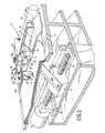
- numeral 1 generally indicates the device for cutting to size tread strips for vehicle tires, according to the present invention.
- the device 1 comprises a substantially horizontal workbench 2, partially shown in the enclosed figures, on which, aligned with the longitudinal axis of the same workbench, there is arranged a tread strip 3 being processed.
- a cutting unit generally indicated by numeral 4, provided with a heated blade 5, moveable through the tread strip 3 so as to cut it in its transverse direction. More particularly, the cut is executed along a plane at an angle with respect to the vertical and along a direction oblique with respect to the length of the tread strip 3.
- the blade 5 is rigidly supported by a control block 6 which is transversely moveable with respect to the workbench 2 along a substantially horizontal direction. More particularly, the block 6 is positioned under the workbench 2 and is slidably engaged along at least one guide bar 7 which extends along the direction of the cut to be executed. The movement of the block 6 is obtained by means of a worm screw 8 rotated by a gearmotor 9 and rotatably engaged between two support brackets 10, only one of which is illustrated, rigidly connected with respect to workbench 2.
- Blade 5 traverses workbench 2 along a slit 11 in the bench itself extending along the direction of displacement of control block 6, so as to cut the tread strip 3 through its thickness and passing through it transversely.
- clamping means 12 arranged to operate on the tread strip 3 at the slit 11 so as to fasten the strip itself against the workbench 2 during the movement of the blade 5, as well as pressure means 13 arranged so as to produce a pressure localized on the tread strip in the immediate vicinity of cutting edge 5a of blade 5 on both parts of said blade and suitable for being displaced on said strip together with and in a direction parallel to said blade, so as to prevent localized deformations of the strip consequent upon the cutting action.
- the clamping means 12 comprise a plate-like fastening element 14, preferably in an elastically deformable metal material, mounted under a supporting arm 15 with one of its extremities operatively connected to an actuating device 16 arranged to one side with respect to the workbench 2 and operating so as to move the plate-like element 14 from a rest condition wherein, as represented by a dotted line in Figures 1 and 2, it is raised from and displaced to one side of the workbench 2, to an operational condition wherein, as indicated with a continuous line in the drawings, it is pushed against tread strip 3 and extends very close to slit 11, in a direction parallel to same.
- the actuating device 16 is only schematically illustrated and shall not be described in detail as it may be accomplished according to several known methods, for example, by the connection of an electromagnet and a rotating fluid-dynamic actuator, arranged to raise and displace to one side, respectively, the arm 15.
- the pressure means 13 essentially comprises a pressure roller 17 and a pressure sphere 18 operatively connected to an auxiliary block 19 rigidly connected to blade 5 above tread strip 3. More accurately, pressure roller 17 is mounted, rotatably on an axis perpendicular to the length of slit 11, to an elastic plate 20 which is rigidly engaged with auxiliary block 19 and which elastically pushes the roller itself towards tread strip 3, close to the cutting edge 5a opposite plate-like element 14.
- the pressure sphere 18 is rotatably housed in a seat in the lower extremity 21a of a bush 21 fastened to the auxiliary block 19 and operatively housing a compression spring 18a which pushes the sphere downwards.
- the preload of spring 18a is preferably adjustable by means of a threaded set screw 18b operatively engaged with the bush 21 and on which the spring itself acts as in an abutment.
- the pressure sphere 18 is positioned adjacent to the side of the cutting edge 5a facing the plate-like element 14 and exerts a pushing action against the plate-like element itself when the latter is in the operative position.
- the plate-like element 14 has two sections of extremities 14a, at respectively opposite ends, bent back at an angle towards workbench 2 to facilitate the upward movement of pressure sphere 18 on the plate-like element itself at the beginning of the cutting action.
- the device 1 may optionally include an auxiliary cutting unit, indicated in a general way at 22 in Figs. 1 and 2, operationally associated with an auxiliary workbench 23 aligned in the same plane as workbench 2 and subjected to the action of adjustment means 24 arranged to move it closer to and further away from workbench 2 to adjust the reciprocal distance between cutting unit 4 and auxiliary cutting unit 22.
- the auxiliary cutting unit 22 is structured in a substantially similar manner to that described with reference to cutting unit 4. A detailed description of the auxiliary cutting unit 22 is therefore considered superfluous.
- the elements comprising it are indicated, in the drawings, with the same numerical references adopted for the components of cutting unit 4 described above.
- the adjustment means 24 provide for an auxiliary workbench 23 (Fig. 2) to be slidably mounted on a guiding frame 25 which allows it to be moved closer to and further away from the workbench 2.
- an actuator 26 having, for example a fluid-dynamic drive, operationally connected with the workbench 2 and with the auxiliary workbench 23 to determine the adjustment of the latter's position on the guiding frame 25.
- roller table 27 equipped with a plurality of idle rollers 27a which support the tread strip 3 in the area included between workbench 2 and auxiliary workbench 23.
- the roller table 27, schematically represented in the drawings, is itself known and is thus not described further. It should, however, be pointed out that roller table 27 is designed so as to increase or decrease the number of rollers 27a between workbenches 2 and 23 simultaneously with the reciprocal displacement of same, so as to adapt itself to support the tread strip 3 independently of the reciprocal distance between the workbenches themselves. It should be pointed out that the roller table 27 is the object of an annual patent application number 90118000.0, filed on 19.09.1990 by the same assignee, to which reference is made for any further clarification and the disclosure of which is hereby specifically incorporated by reference.
- the distance between cutting units 4 and 22 has already been adjusted in relation to the length to which the tread strips 3 are to be cut, it is first of all provided for that the tread strip to be cut is to be positioned on workbenches 2 and 23, so that the opposite ends of a tread strip are over slit 11 in each table.
- the plate-like elements 14, initially in the rest position, are moved to their operative positions by the actuating devices 16, to execute the fastening of the tread strip 3 to the workbenches 2, 23.
- the cutting blades 5, heated in a conventional manner by means of electrical resistances associated with them, are made to translate horizontally along their respective slits 11, so as to cut the tread strip 3.
- each blade 5 is arranged to cut the tread strip 3 through its thickness, there is a limited contact surface and, thus, a limited heat exchange between the blade and the tread strip itself.
- the blade 5 thus gives up its heat very slowly to the elastomeric material constituting the tread strip 3.
- the heat taken from the blade in the areas of contact with the tread strip 3 is replaced along the way by the heat coming from the remaining parts of the blade itself, transmitted by conduction to the above contact surfaces, which consequently maintain an almost constant temperature throughout the execution of the cut.
- the sphere 18 is used to act on a substantially punctiform area of the plate-like element 14 exerting on it a high specific pressure: on the other hand, due to the effect of the elasticity of the plate-like element itself, such pressure is suitably distributed on tread strip 3, with a reduced value so as to maintain a localized action but without the occurrence of deformation effects which would otherwise be caused on the strip by the above punctiform pressure.
- roller 17 transmits its pressure action directly to the tread strip 3, along a substantially linear contact area.
- the plate-like fastening elements 14 are returned to the rest position, the cut off end scraps of the section are removed from the workbench and the tread strip, cut to size, and slid over said workbenches 2 and 23, can be fed to an adjacent machine for manufacturing tires.
- the general process for the manufacture of tires provides for the preparation of a carcass in the shape of cylindrical sleeve over a suitable production drum, for the separate preparation of the tread strip by reducing to the required size, that is, to the pre-set length, a section of elastomeric material previously cut to a length greater than that of the strip, for the conformation of the above carcass to a toroidal shape, assembling with it the further elements that are needed such as the sidewalls, the reinforcement edges and the intermediate belt, and in particular assembling with the above toric shaped carcass the above-mentioned tread strip, welded in the shape of a ring by means of a head-to-head joint of the two opposite beveled ends.
- the present invention solves the problems described above. It is in fact seen that the above device is designed to ensure the maintenance of a suitable temperature in the proximity of the blade's cutting edge during the execution of the cut. It should be noted in this respect that, should the blade's cutting edge cool too much by the end of the cutting stage, the tread strip obtained would have imperfections in the bevel cut at only the proximity of one of its side edges, that is in an area where the stresses consequent on the use of the finished tire are fairly limited. Moreover the above device and process allow a prefect execution of the cut in spite of the fact that the penetration of the blades into the strip occurs in a transverse sense.
- the process according to the invention prepares a tread strip of the required length starting from a section of elastomeric material having a greater length than needed and executing on the section two simultaneous cuts, one on each end thereof.
Applications Claiming Priority (2)
| Application Number | Priority Date | Filing Date | Title |
|---|---|---|---|
| IT19492A IT1239347B (it) | 1990-02-26 | 1990-02-26 | Apparecchiatura per il taglio a misura di fasce battistrada per pneumatici di veicoli,e procedimento di taglio attuato da detta apparecchiatura |
| IT1949290 | 1990-02-26 |
Publications (1)
| Publication Number | Publication Date |
|---|---|
| EP0444573A1 true EP0444573A1 (de) | 1991-09-04 |
Family
ID=11158487
Family Applications (1)
| Application Number | Title | Priority Date | Filing Date |
|---|---|---|---|
| EP91102734A Withdrawn EP0444573A1 (de) | 1990-02-26 | 1991-02-25 | Vorrichtung zum Abschneiden von Laufflächenstreifen für Fahrzeugreifen und Schneideverfahren mit dieser Vorrichtung |
Country Status (4)
| Country | Link |
|---|---|
| EP (1) | EP0444573A1 (de) |
| JP (1) | JPH04216034A (de) |
| BR (1) | BR9100860A (de) |
| IT (1) | IT1239347B (de) |
Cited By (11)
| Publication number | Priority date | Publication date | Assignee | Title |
|---|---|---|---|---|
| WO2000051810A1 (en) * | 1999-03-03 | 2000-09-08 | The Goodyear Tire & Rubber Company | Forming splice joints for elastomeric materials |
| EP1145836A2 (de) * | 2000-01-27 | 2001-10-17 | Bandag Incorporated | Verfahren und Vorrichtung zur Vorbereitung der Lauffläche eines rundzuerneuernden Reifens |
| EP1262288A2 (de) * | 2001-06-01 | 2002-12-04 | The Goodyear Tire & Rubber Company | Verfahren sowie Vorrichtung zum Schneiden von elastomerischen Materialien |
| US6592704B1 (en) | 1999-03-03 | 2003-07-15 | The Goodyear Tire & Rubber Company | Forming splice joints for elastomeric materials |
| US6758931B1 (en) | 2000-01-27 | 2004-07-06 | Bandag, Incorporated | Method and apparatus for applying tire tread for a retread tire |
| US7455002B2 (en) | 2004-12-23 | 2008-11-25 | The Goodyear Tire & Rubber Company | Method for cutting elastomeric materials and the article made by the method |
| US7524398B2 (en) | 2004-12-23 | 2009-04-28 | The Goodyear Tire & Rubber Company | Apparatus for making tire components, and a tire |
| US8561511B2 (en) | 2004-12-23 | 2013-10-22 | The Goodyear Tire & Rubber Company | Anvil with vacuum width adjustment |
| US8794117B2 (en) | 2004-10-01 | 2014-08-05 | The Goodyear Tire & Rubber Company | Apparatus for cutting elastomeric materials |
| CN113484107A (zh) * | 2021-05-20 | 2021-10-08 | 扬州大学 | 一种Overlay试件专用切割装置 |
| CN114888868A (zh) * | 2022-05-27 | 2022-08-12 | 龚重园 | 一种建筑装饰板加工床 |
Families Citing this family (3)
| Publication number | Priority date | Publication date | Assignee | Title |
|---|---|---|---|---|
| JP2010162997A (ja) * | 2009-01-14 | 2010-07-29 | Yokohama Rubber Co Ltd:The | 空気入りタイヤ及びその製造方法 |
| CN104972493B (zh) * | 2015-06-30 | 2016-08-24 | 重庆市金盾橡胶制品有限公司 | 一种胎面分离切割机 |
| CN108312585A (zh) * | 2018-02-10 | 2018-07-24 | 无锡微研中佳精机科技有限公司 | 一种轮胎胎面夹拽机构 |
Citations (5)
| Publication number | Priority date | Publication date | Assignee | Title |
|---|---|---|---|---|
| FR1323228A (fr) * | 1962-05-07 | 1963-04-05 | Goodyear Tire & Rubber | épissure à recouvrement pour tissu câblé recouvert d'un revêtement, procédé et appareil pour son exécution |
| CH420597A (de) * | 1964-03-26 | 1966-09-15 | Firestone Prod | Vorrichtung zum Trennen von Gewebe- oder Folienbahnen zur Herstellung von Fahrzeugreifen |
| DE1301047B (de) * | 1964-12-19 | 1969-08-14 | Dunlop Ag | Verfahren und Schneidmaschine zum Schneiden einer Stahlseilbahn |
| GB1293823A (en) * | 1969-05-13 | 1972-10-25 | Herbert Maschf L | Device for cutting cord webs to size for the production of pneumatic tyres |
| EP0418849A2 (de) * | 1989-09-22 | 1991-03-27 | PIRELLI COORDINAMENTO PNEUMATICI Società per Azioni | Rollentisch mit variabler Länge |
-
1990
- 1990-02-26 IT IT19492A patent/IT1239347B/it active IP Right Grant
-
1991
- 1991-02-25 EP EP91102734A patent/EP0444573A1/de not_active Withdrawn
- 1991-02-26 JP JP3030985A patent/JPH04216034A/ja active Pending
- 1991-02-26 BR BR919100860A patent/BR9100860A/pt not_active IP Right Cessation
Patent Citations (5)
| Publication number | Priority date | Publication date | Assignee | Title |
|---|---|---|---|---|
| FR1323228A (fr) * | 1962-05-07 | 1963-04-05 | Goodyear Tire & Rubber | épissure à recouvrement pour tissu câblé recouvert d'un revêtement, procédé et appareil pour son exécution |
| CH420597A (de) * | 1964-03-26 | 1966-09-15 | Firestone Prod | Vorrichtung zum Trennen von Gewebe- oder Folienbahnen zur Herstellung von Fahrzeugreifen |
| DE1301047B (de) * | 1964-12-19 | 1969-08-14 | Dunlop Ag | Verfahren und Schneidmaschine zum Schneiden einer Stahlseilbahn |
| GB1293823A (en) * | 1969-05-13 | 1972-10-25 | Herbert Maschf L | Device for cutting cord webs to size for the production of pneumatic tyres |
| EP0418849A2 (de) * | 1989-09-22 | 1991-03-27 | PIRELLI COORDINAMENTO PNEUMATICI Società per Azioni | Rollentisch mit variabler Länge |
Cited By (17)
| Publication number | Priority date | Publication date | Assignee | Title |
|---|---|---|---|---|
| US6592704B1 (en) | 1999-03-03 | 2003-07-15 | The Goodyear Tire & Rubber Company | Forming splice joints for elastomeric materials |
| WO2000051810A1 (en) * | 1999-03-03 | 2000-09-08 | The Goodyear Tire & Rubber Company | Forming splice joints for elastomeric materials |
| EP1145836A2 (de) * | 2000-01-27 | 2001-10-17 | Bandag Incorporated | Verfahren und Vorrichtung zur Vorbereitung der Lauffläche eines rundzuerneuernden Reifens |
| EP1145836A3 (de) * | 2000-01-27 | 2001-10-24 | Bandag Incorporated | Verfahren und Vorrichtung zur Vorbereitung der Lauffläche eines rundzuerneuernden Reifens |
| US6758931B1 (en) | 2000-01-27 | 2004-07-06 | Bandag, Incorporated | Method and apparatus for applying tire tread for a retread tire |
| US6899778B1 (en) | 2000-01-27 | 2005-05-31 | Bandag Incorporated | Method and apparatus for preparing tire tread for a retread tire |
| US7526986B2 (en) | 2001-06-01 | 2009-05-05 | The Goodyear Tire & Rubber Company | Method for cutting elastomeric materials |
| EP1262288A2 (de) * | 2001-06-01 | 2002-12-04 | The Goodyear Tire & Rubber Company | Verfahren sowie Vorrichtung zum Schneiden von elastomerischen Materialien |
| EP1262288A3 (de) * | 2001-06-01 | 2004-10-13 | The Goodyear Tire & Rubber Company | Verfahren sowie Vorrichtung zum Schneiden von elastomerischen Materialien |
| US8794117B2 (en) | 2004-10-01 | 2014-08-05 | The Goodyear Tire & Rubber Company | Apparatus for cutting elastomeric materials |
| US7524398B2 (en) | 2004-12-23 | 2009-04-28 | The Goodyear Tire & Rubber Company | Apparatus for making tire components, and a tire |
| US8561511B2 (en) | 2004-12-23 | 2013-10-22 | The Goodyear Tire & Rubber Company | Anvil with vacuum width adjustment |
| US7455002B2 (en) | 2004-12-23 | 2008-11-25 | The Goodyear Tire & Rubber Company | Method for cutting elastomeric materials and the article made by the method |
| CN113484107A (zh) * | 2021-05-20 | 2021-10-08 | 扬州大学 | 一种Overlay试件专用切割装置 |
| CN113484107B (zh) * | 2021-05-20 | 2023-12-08 | 扬州大学 | 一种Overlay试件专用切割装置 |
| CN114888868A (zh) * | 2022-05-27 | 2022-08-12 | 龚重园 | 一种建筑装饰板加工床 |
| CN114888868B (zh) * | 2022-05-27 | 2024-04-12 | 长沙迪奥装饰工程有限公司 | 一种建筑装饰板加工床 |
Also Published As
| Publication number | Publication date |
|---|---|
| BR9100860A (pt) | 1991-11-05 |
| IT9019492A0 (it) | 1990-02-26 |
| IT1239347B (it) | 1993-10-20 |
| JPH04216034A (ja) | 1992-08-06 |
| IT9019492A1 (it) | 1991-08-26 |
Similar Documents
| Publication | Publication Date | Title |
|---|---|---|
| EP0444573A1 (de) | Vorrichtung zum Abschneiden von Laufflächenstreifen für Fahrzeugreifen und Schneideverfahren mit dieser Vorrichtung | |
| US2293721A (en) | Method of and apparatus for cutting and splicing thick rubber stock and the like | |
| CN209207661U (zh) | 防尘膜裁切机 | |
| KR960013243B1 (ko) | 플라스틱 재질 시이트의 절단 장치 | |
| GB1584024A (en) | Apparatus for cutting glass sheets | |
| CN109483633B (zh) | 一种双工位导电胶条切条机 | |
| WO1996006723A1 (en) | Method and apparatus for joining plastic materials together | |
| CN114603263A (zh) | 一种自动校准可防偏移的激光切割设备及其方法 | |
| US3607576A (en) | Wire overhead machine | |
| CN208246883U (zh) | 一种胎面自动定长裁切装置 | |
| US2893479A (en) | Tire truing device comprising hydraulically operated tire support and adjustable cam operated cutting tool | |
| CN108437503B (zh) | 一种缠绕胶片的热切刀装置 | |
| JPH0212746B2 (de) | ||
| KR200439296Y1 (ko) | 샌드위치패널 커팅장치 | |
| CN219650030U (zh) | 一种滤芯修边机 | |
| CN109366601B (zh) | 一种四工位导电胶条切条机 | |
| RU2246386C1 (ru) | Машина для контактной стыковой сварки полос | |
| JPS626959B2 (de) | ||
| CN219667544U (zh) | 轮胎自动成型机 | |
| JP3014599B2 (ja) | 帯状材料の自動接続方法及び装置 | |
| JPH10244416A (ja) | 長尺部材の切断装置 | |
| CN219294382U (zh) | 一种热敏电阻制造用切片机 | |
| CN213226463U (zh) | 一种汽车胶条切边机的定位机构 | |
| CN220945466U (en) | Sponge cutting equipment | |
| CN219075795U (zh) | 一种板材定长截断机 |
Legal Events
| Date | Code | Title | Description |
|---|---|---|---|
| PUAI | Public reference made under article 153(3) epc to a published international application that has entered the european phase |
Free format text: ORIGINAL CODE: 0009012 |
|
| AK | Designated contracting states |
Kind code of ref document: A1 Designated state(s): DE ES FR GB GR |
|
| STAA | Information on the status of an ep patent application or granted ep patent |
Free format text: STATUS: THE APPLICATION HAS BEEN WITHDRAWN |
|
| 18W | Application withdrawn |
Withdrawal date: 19920413 |