EP0443497A2 - Appareil de détection de luminosité de l'arrière-plan d'une caméra - Google Patents
Appareil de détection de luminosité de l'arrière-plan d'une caméra Download PDFInfo
- Publication number
- EP0443497A2 EP0443497A2 EP91102290A EP91102290A EP0443497A2 EP 0443497 A2 EP0443497 A2 EP 0443497A2 EP 91102290 A EP91102290 A EP 91102290A EP 91102290 A EP91102290 A EP 91102290A EP 0443497 A2 EP0443497 A2 EP 0443497A2
- Authority
- EP
- European Patent Office
- Prior art keywords
- rear light
- light
- central area
- detecting
- main object
- Prior art date
- Legal status (The legal status is an assumption and is not a legal conclusion. Google has not performed a legal analysis and makes no representation as to the accuracy of the status listed.)
- Withdrawn
Links
Images




Classifications
-
- G—PHYSICS
- G01—MEASURING; TESTING
- G01J—MEASUREMENT OF INTENSITY, VELOCITY, SPECTRAL CONTENT, POLARISATION, PHASE OR PULSE CHARACTERISTICS OF INFRARED, VISIBLE OR ULTRAVIOLET LIGHT; COLORIMETRY; RADIATION PYROMETRY
- G01J1/00—Photometry, e.g. photographic exposure meter
- G01J1/42—Photometry, e.g. photographic exposure meter using electric radiation detectors
- G01J1/44—Electric circuits
-
- G—PHYSICS
- G03—PHOTOGRAPHY; CINEMATOGRAPHY; ANALOGOUS TECHNIQUES USING WAVES OTHER THAN OPTICAL WAVES; ELECTROGRAPHY; HOLOGRAPHY
- G03B—APPARATUS OR ARRANGEMENTS FOR TAKING PHOTOGRAPHS OR FOR PROJECTING OR VIEWING THEM; APPARATUS OR ARRANGEMENTS EMPLOYING ANALOGOUS TECHNIQUES USING WAVES OTHER THAN OPTICAL WAVES; ACCESSORIES THEREFOR
- G03B7/00—Control of exposure by setting shutters, diaphragms or filters, separately or conjointly
- G03B7/28—Circuitry to measure or to take account of the object contrast
Definitions
- This invention relates to a rear light detecting apparatus in a camera for detecting whether an object is in rear light.
- this camera which automatically accomplishes daylight synchronized flash photographing. That is, this camera detects the brightness of an object lying in the central area of the photographing picture plane and the brightness of an object lying in the peripheral area of the central area, and judges the object in the central area to be in a rear light state when the brightness of the object in the central area is lower by a predetermined value or greater than the brightness of the object in the peripheral area, and causes an electronic flash device to emit light during photographing to thereby effect daylight synchronized flash photographing. According to this, failure such as the object in the central area being defaced in flack due to under-exposure is prevented.
- the present invention is applied to a rear light detecting apparatus in a camera which is provided with a center portion light meter 101 for detecting the brightness of an object lying in the central area of the photographing picture plane, a peripheral portion light meter 102 for detecting the brightness of an object lying in the peripheral area of the central area, a first rear light discriminator 103 for judging on the basis of the result of the detection by the two light meters 101 and 102 whether the object lying in the central area is in a rear light state, and a controller 104 outputting, when said object is judged to be in rear light state, a light emission signal for causing an electronic flash device to emit light during photographing.
- the rear light detecting apparatus is further provided with a focus detector 106 for detecting the focuses of a plurality of objects lying in at least a predetermined detection area within the central area of the picture plane from a pair of object images formed on an image sensor 105, an object selector 107 for selecting the main object on the basis of the result of the detection by the focus detector 106, and a second rear light discriminator 108 for judging from image sensor outputs corresponding to the selected main object and the other objects whether the main object is in a rear light state, and achieves the above-described technical task by constructing the controller 104 as follows.
- the controller 104 outputs said light emission signal when at least one of the first and second rear light discriminators 103 and 108 judges the main object to be in a rear light state.
- the present invention is applied to a rear light detecting apparatus in a camera which is provided with said center portion light meter 101, said peripheral portion light meter 102, a calculator 201 for calculating the exposure value during photographing from the result of the detection by said light meters 101 and 102, said first rear light discriminator 103, and an exposure compensator 202 for applying the compensation of the over side to the exposure value calculated by the calculator 201 when the main object is judged to be in a rear light state.
- the rear light detecting apparatus is further provided with said focus detector 106, said object selector 107 and said second rear light discriminator 108, and achieves the above-described technical task by constructing said exposure compensator 202 as follows.
- the exposure compensator 202 applies the compensation of said over side when at least one of the first and second rear light discriminators 103 and 108 judges the main object to be in a rear light state.
- the predetermined detection area in which the focus detector 106 effects focus detection may extend into the peripheral area, in addition to the central area of the picture plane.
- the focus detector 106 detects the focuses of a plurality of objects lying in at least the predetermined detection area within the central area of the picture plane from a pair of object images formed on the image sensor 105, and the object selector 107 selects the main object on the basis of the result of the detection.
- the second rear light discriminator 108 judges from image sensor outputs corresponding to the selected main object and the other objects whether the main object is in a rear light state.
- the controller 104 outputs, when at least one of the first and second rear light discriminators 103 and 108 judges the main object to be in a rear light state, a light emission signal during photographing to thereby cause the electronic flash device to emit light. That is, it effects daylight synchronized flash photographing.
- the first rear light discriminator 103 judges the main object to be not in rear light
- the second rear light discriminator 108 judges the main object to be in a rear light state and therefore, daylight synchronized flash photographing is effected.
- the exposure compensator 202 applies the compensation of the over side to the exposure value calculated by the calculator 201 when at least one of the first and second rear light discriminators 103 and 108 judges the main object to be in a rear light state. According to this, as described above, even when the main object in the central area of the picture plane (which is in a rear light state) is small, the second rear light discriminator 108 judges the main object to be in a rear light state and therefore, exposure compensation is effected.
- the predetermined area in which focus detection is effected is designed to extend to the peripheral area as well, even if an object which is in a rear light state is not in the central area of the picture plane but in the peripheral area, rear light judgment is done by the second rear light discriminator 108 and daylight synchronized flash photographing or exposure compensation is effected.
- FIGS. 1A and 1B are block diagrams of a rear light detecting apparatus in a camera according to the present invention.
- Figures 2 to 6 show an embodiment of the present invention
- Figure 2 being a block diagram showing the general construction of a rear light detecting apparatus according to the present invention
- Figure 3 illustrating a focus detecting system and a light metering system
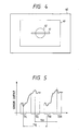
- Figure 4 showing the focus detection area and the light metering area on the photographing picture plane
- Figure 5 showing an example of the output of an image sensor
- Figure 6 is a flow chart of the processing procedure.
- FIGS 7A to 7D illustrate the rear light judgments in various objects.
- a control circuit 10 has a main object rear light discrimination portion 11, a center portion object rear light discrimination portion 12 and a control portion 13, and a main object detector 21 is connected to the main object rear light discrimination portion 11.
- the detection output of an image sensor 22 for focus detection may be input to the main object detector 21.
- the image sensor 22 is disposed within a camera body 1, as shown in Figure 3, and a pair of object lights passed through a pair of lenses 31 and 32 and reflected by reflecting mirrors 33, 34 and 35 are imaged on the image sensor 22, and the object images are output as a pair of image signals to the main object detector 21.
- These object lights are the reflected light from an object lying in a focus detection area 41 laterally extending substantially in the central portion of a photographing picture plane 40 shown in Figure 4.
- Figure 5 shows an example of the sensor output, i.e., the image signal, when two object lights differing in object distance are projected onto the image sensor 22, and it is to be understood that one object is projected onto areas 71R and 71L on the image sensor 22 and the other objects are projected onto areas 72R and 72L on the image sensor 22.
- the main object detector 21 effects focus detection calculation on the basis of these image signals and calculates the distance to each object (the object distance) from the intervals 71d and 72d of the respective object images (this corresponds to focus detection, and judges, for example, the object at a shorter distance to be the main object, and inputs the position of the main object in the picture plane 40 to the main object rear light discrimination portion 11 of the control circuit 10. That is, it selects the main object.
- the position of the main object and said image signals are also input to an AF circuit, not shown, and on the basis of these, the AF circuit calculates an amount of lens driving for focusing a photo-taking lens (not shown) on the main object.
- a center portion light sensor 23 and a peripheral portion light sensor 24 are connected to the center portion object rear light discrimination portion 12 in the control circuit 10.
- the center portion light sensor 23 receives the reflected light from an object lying in the circular central area 42 of the picture plane 40 ( Figure 3) through a lens 36 ( Figure 3), and detects the brightness of that object therefrom and inputs it to the center portion object rear light discrimination portion 12.
- the peripheral portion light sensor 24 likewise detects the brightness of an object lying in the peripheral area 43 of the central area 42 and inputs it to the center portion object rear light discrimination portion 12.
- the center portion of the above-mentioned focus detection area 41 lies in the central area 42, and the opposite end portions of the focus detection area 41 extend into the peripheral area 43.
- an exposure control circuit 51 and the flash control circuit 52 of an electronic flash device are connected to the control portion 13 of the control circuit 10.
- the exposure control circuit 51 drives a diaphragm and a shutter, not shown, by a command from the control portion 13 and effects photographing
- the flash control circuit 52 is responsive to a light emission signal output from the control portion to cause a light emitting tube, not shown, to emit light to illuminate the objects.
- this program starts and first, at a step S1, the image sensor 22 is operated through the main object detector 21. Thereby, the image sensor 22 inputs to the main object detector 21 the image of the object lying in the focus detection area 41 of Figure 4 as an image signal. Subsequently, at a step S2, the control circuit 10 outputs an operation signal to the main object detector 21 and calculates the film-to-object distance of each object by the above-described focus detection calculation, and at a step S3, inputs to the main object rear light discrimination portion 11 the position in the picture plane 40 of the main object selected on the basis thereof.
- the object projected onto the areas 71L and 71R is the object of a shorter distance, i.e., the main object. Also at this time, the output of the image sensor 22 is input to the main object rear light discrimination portion 11.
- the detection outputs of the center portion light sensor 23 and the peripheral portion light sensor 24, i.e., the brightnesses of the objects in the central area 42 and the peripheral area 43, are input to the center portion object rear light discrimination portion 12, and advance is made to a step S6.
- the step S6 from the position of the main object input at the step S3 and the output of the image sensor 22 (the image signal), whether the main object is in a rear light state is judged by the main object rear light discrimination portion 11.
- the main object rear light discrimination portion 11 judges the main object to be in a rear light state, and in this case, advance is made to a step S7.
- the comparison between said sensor outputs may be done by the difference between the two sensor outputs, or may be done by the ratio therebetween.
- step S7 daylight synchronized flash photographing is effected. That is, the result of the judgment that the main object is in a rear light state is input to the control portion 13, whereby the control portion 13 drives a diaphragm and a shutter, not shown, through the exposure control circuit 51, for example, with the full depression of the release button, and also outputs a light emission signal to the flash control circuit 52 of the electronic flash device. With the outputting of this light emission signal, the flash control circuit 52 causes a light emitting tube, not shown, to emit light and illuminate the object.
- the main object is judged to be not in a rear light state, and in this case, advance is made to a step S8.
- step S8 whether the object in the central area 42 (regarded as the main object) is in a rear light state is judged from the brightnesses of the objects in the central area 42 and the peripheral area 43 input at the steps S4 and S5. That is, if the brightness of the object in the central area 42 is lower by a predetermined value or more than the brightness of the object in the peripheral area 43, the main object is judged to be in a rear light state and advance is made to the above-described step S7, and in the other case, the main object is judged to be not in a rear light state and advance is made to a step S9.
- step S9 ordinary photographing in which the electronic flash device is not caused to emit light is effected to thereby terminate the process. This rear light judgment may be done by the difference between the brightnesses of the objects in the areas 42 and 43, or may be done by the ratio therebetween.
- the judgment by the light sensor determines whether the object in the central area 42 is in a rear light state from the brightness of the object in the central area 42 and the brightness of the object in the peripheral area 43 (this will hereinafter be referred to as the judgment by the light sensor), and whether the main object is in a rear light state is judged from the outputs of the image sensor 22 which correspond to the main object and the other object (this will hereinafter be referred to as the judgment by the image sensor).
- the judgment by the image sensor is not affected by the size (area) of the main object like the judgment by the light sensor because whether the main object is in a rear light state is judged from the height of the sensor output in the focus detection area 41, and judgment of rear light can be accurately effected even for small objects. If rear light is judged in at least one of the above-described two judgments, daylight synchronized flash photographing accompanied by the light emission of the electronic flash device is effected.
- Figures 7A to 7D show the rear light judgment situations by the positions or the sizes of the main objects (figures) 81, and it is to be understood that each of the main objects 81 is in a rear light state.
- the main object 81 is substantially at the center of the photographing picture plane and moreover is of a size large enough to fully cover the central area 42, both of the judgments by the light sensor and the image sensor are rear light judgments, whereby daylight synchronized flash photographing is effected.
- the judgment by the image sensor is rear light judgment (the judgment by the light sensor is non-rear light judgment) and again in this case, daylight synchronized flash photographing is effected. That is, in the present embodiment, the end portion of the image sensor 22 extends to the peripheral area and therefore, even if the main object is not in the central area 42, a rear light state can be judged.
- the center portion light sensor 23 constitutes the center portion light meter 101
- the peripheral portion light sensor 24 constitutes the peripheral portion light meter 102
- the center portion object rear light discrimination portion 12 constitutes the first rear light discriminator 103
- the main object detector 21 constitutes the focus detector 106 and the object selector 107
- the main object rear light discrimination portion 11 constitutes the second rear light discriminator 108
- the control portion 13 constitutes the controller 104.
- design is made such that daylight synchronized flash photographing is effected when rear light is judged, but alternatively, design may be made such that exposure compensation is effected instead of the daylight synchronized flash photographing. That is, if in a camera wherein the exposure value during photographing is calculated from the result of the detection by the light sensors 23 and 24, at least one of the judgments by the light sensors and the image sensor is rear light judgement, the compensation of the over side is applied to the calculated exposure value.
- the embodiment has been shown as an example in which the opposite end portions of the focus detection area 41 extend to the peripheral area 43, only one of the end portions may extend to the peripheral area 43, or the focus detection area 41 may be fully within the central area 42. Where the area 41 is thus designed to be fully within the central area 42, rear light judgment cannot be done if the main object 81 is not in the central area 42, but if the main object 81 is in the central area 42, the main object can be judged to be in a rear light state even though its size is small.
- the electronic flash device may be contained within the camera or may be attached to the exterior of the camera.
- use is made of the image sensor 22 also for use for AF, but alternatively, provision may be made of an image sensor for exclusive use.
- the utilization of the existing image sensor for AF can achieve the simplification of the construction and a reduction in the number of parts and cost, as compared with the use of a sensor for exclusive use.
- design is made such that whether the object in the central area is in a rear light state is judged from the brightnesses of the objects in the central area of the picture plane and the peripheral area thereof and whether the main object lying in the focus detection area within the central area is in a rear light state is judged from the output of the image sensor for focus detection and that if at least one of the two judgments is rear light judgment, daylight synchronized flash photographing is effected and therefore, even if the object in the central area is small, rear light judgment can be done reliably and daylight synchronized flash photographing is effected, whereby photographing can be accomplished reliably at proper exposure even if the main object is in a rear light state.
- design is made such that if at least one of said two judgments is rear light judgment, the exposure during photographing is corrected to the over side and therefore, as described above, even if the object in the central area is small, rear light judgment can be done reliably, and by said correction, photographing can be accomplished reliably at proper exposure even if the main object is in a rear light state.
- design is made such that the focus detection area extends to the peripheral area and therefore, in addition to the above-described effects, even whether an object lying in the peripheral area is in a rear light state can be judged and thus, photographing at proper exposure becomes possible by daylight synchronized flash photographing or exposure compensation.
Landscapes
- Physics & Mathematics (AREA)
- General Physics & Mathematics (AREA)
- Spectroscopy & Molecular Physics (AREA)
- Exposure Control For Cameras (AREA)
- Focusing (AREA)
- Photometry And Measurement Of Optical Pulse Characteristics (AREA)
- Automatic Focus Adjustment (AREA)
Applications Claiming Priority (2)
| Application Number | Priority Date | Filing Date | Title |
|---|---|---|---|
| JP37918/90 | 1990-02-19 | ||
| JP2037918A JP2934712B2 (ja) | 1990-02-19 | 1990-02-19 | カメラの逆光検出装置 |
Publications (2)
| Publication Number | Publication Date |
|---|---|
| EP0443497A2 true EP0443497A2 (fr) | 1991-08-28 |
| EP0443497A3 EP0443497A3 (en) | 1992-04-08 |
Family
ID=12510926
Family Applications (1)
| Application Number | Title | Priority Date | Filing Date |
|---|---|---|---|
| EP19910102290 Withdrawn EP0443497A3 (en) | 1990-02-19 | 1991-02-18 | Rear light detecting apparatus in a camera |
Country Status (3)
| Country | Link |
|---|---|
| US (1) | US5128707A (fr) |
| EP (1) | EP0443497A3 (fr) |
| JP (1) | JP2934712B2 (fr) |
Cited By (2)
| Publication number | Priority date | Publication date | Assignee | Title |
|---|---|---|---|---|
| EP0532047A3 (en) * | 1991-09-12 | 1994-06-15 | Fuji Photo Film Co Ltd | Method of making photographic prints |
| EP1531356A1 (fr) * | 2003-11-15 | 2005-05-18 | Hewlett-Packard Development Company, L.P. | Méthode et système pour la compensation d'exposition utilisant une matrice photométrique et un dispositif de flash |
Families Citing this family (12)
| Publication number | Priority date | Publication date | Assignee | Title |
|---|---|---|---|---|
| US5319416A (en) * | 1990-10-16 | 1994-06-07 | Nikon Corporation | Exposure calculation device for camera |
| JP3127543B2 (ja) * | 1992-01-29 | 2001-01-29 | 株式会社ニコン | 閃光手段と焦点検出手段とを有するカメラシステム |
| US5526088A (en) * | 1992-03-05 | 1996-06-11 | Nikon Corporation | Focus detection device |
| US5302997A (en) * | 1992-12-28 | 1994-04-12 | Eastman Kodak Company | Composite photometric and range finding element array |
| JPH06230453A (ja) * | 1993-02-02 | 1994-08-19 | Nikon Corp | 被写体追尾機能を有するカメラ |
| US6195127B1 (en) * | 1996-07-18 | 2001-02-27 | Sanyo Electric Co., Ltd. | Digital camera, having a flash unit, which determines proper flash duration through an assessment of image luminance and, where needed, a preliminary flash emission |
| JP2001141987A (ja) * | 1999-11-17 | 2001-05-25 | Olympus Optical Co Ltd | 測距装置 |
| US6920286B2 (en) | 2002-04-02 | 2005-07-19 | Olympus Corporation | Camera having proper exposure controlling function |
| US6853806B2 (en) | 2002-09-13 | 2005-02-08 | Olympus Optical Co., Ltd. | Camera with an exposure control function |
| JP4537255B2 (ja) * | 2005-04-28 | 2010-09-01 | 富士フイルム株式会社 | 撮像装置および撮像方法 |
| US7683964B2 (en) | 2005-09-05 | 2010-03-23 | Sony Corporation | Image capturing apparatus and image capturing method |
| US20100118175A1 (en) * | 2008-11-10 | 2010-05-13 | Victor Charles Bruce | Imaging Apparatus For Image Integration |
Family Cites Families (11)
| Publication number | Priority date | Publication date | Assignee | Title |
|---|---|---|---|---|
| US4285584A (en) * | 1979-10-02 | 1981-08-25 | Polaroid Corporation | Photometric device |
| US4423936A (en) * | 1982-07-26 | 1984-01-03 | Polaroid Corporation | Photographic exposure control system and method |
| US4603958A (en) * | 1983-11-15 | 1986-08-05 | West Electric Company, Ltd. | Automatic electronic flash |
| US4664495A (en) * | 1984-04-09 | 1987-05-12 | Canon Kabushiki Kaisha | Rear light detecting device for camera |
| US4862206A (en) * | 1984-10-12 | 1989-08-29 | Minolta Camera Kabushiki Kaisha | Exposure control system |
| US4821074A (en) * | 1985-09-09 | 1989-04-11 | Minolta Camera Kabushiki Kaisha | Exposure control device for a camera |
| US4705382A (en) * | 1985-10-16 | 1987-11-10 | Minolta Camera Kabushiki Kaisha | Flash photographing apparatus |
| JP2592904B2 (ja) * | 1988-05-06 | 1997-03-19 | キヤノン株式会社 | カメラ |
| US4963915A (en) * | 1988-05-16 | 1990-10-16 | Minolta Camera Kabushiki Kaisha | Brightness measuring apparatus for providing adequate object brightness and a flashlight emission apparatus providing adequate exposure, irrespective of photographing conditions |
| US4974012A (en) * | 1988-06-28 | 1990-11-27 | Canon Kabushiki Kaisha | Display device for automatic exposure bracketing shooting |
| JPH06105334B2 (ja) * | 1988-07-08 | 1994-12-21 | 旭光学工業株式会社 | 分割測光装置 |
-
1990
- 1990-02-19 JP JP2037918A patent/JP2934712B2/ja not_active Expired - Fee Related
-
1991
- 1991-02-14 US US07/655,350 patent/US5128707A/en not_active Expired - Fee Related
- 1991-02-18 EP EP19910102290 patent/EP0443497A3/en not_active Withdrawn
Cited By (3)
| Publication number | Priority date | Publication date | Assignee | Title |
|---|---|---|---|---|
| EP0532047A3 (en) * | 1991-09-12 | 1994-06-15 | Fuji Photo Film Co Ltd | Method of making photographic prints |
| US5404196A (en) * | 1991-09-12 | 1995-04-04 | Fuji Photo Film Co., Ltd. | Method of making photographic prints |
| EP1531356A1 (fr) * | 2003-11-15 | 2005-05-18 | Hewlett-Packard Development Company, L.P. | Méthode et système pour la compensation d'exposition utilisant une matrice photométrique et un dispositif de flash |
Also Published As
| Publication number | Publication date |
|---|---|
| US5128707A (en) | 1992-07-07 |
| JP2934712B2 (ja) | 1999-08-16 |
| JPH03240030A (ja) | 1991-10-25 |
| EP0443497A3 (en) | 1992-04-08 |
Similar Documents
| Publication | Publication Date | Title |
|---|---|---|
| US5128707A (en) | Rear light detecting apparatus in a camera | |
| US6240253B1 (en) | Automatic focusing camera | |
| JPH0427530B2 (fr) | ||
| US6246837B1 (en) | Image sensing apparatus | |
| US9268196B2 (en) | Image capture apparatus, light emitting device, and and light emission amount calculation method | |
| US5587766A (en) | Camera which sets an internal aperture value in accordance with a converted photographic lens aperture value | |
| JP2004004449A (ja) | カメラの露出制御システム | |
| JPH11118477A (ja) | 測距装置 | |
| JP4512173B2 (ja) | 測距装置 | |
| JPH02100027A (ja) | 被写体輝度の測定方法 | |
| JP2002277920A (ja) | 露出制御方法及び撮影装置 | |
| JPH095611A (ja) | 測距装置 | |
| JP3229982B2 (ja) | 分割測光が可能なカメラ | |
| JP2003215441A (ja) | カメラ | |
| JP4288407B2 (ja) | カメラ、電子閃光装置、及びカメラシステム | |
| JP3568211B2 (ja) | カメラ | |
| KR20010026698A (ko) | 자동 카메라 시스템의 자동 역광 보정 장치 및 방법 | |
| JPH02190832A (ja) | 自動焦点調整機能付カメラの測光装置 | |
| JPH0749513A (ja) | フラッシュ光量制御装置 | |
| KR200170178Y1 (ko) | 보조광을 이용한 카메라의 패시브 방식의 자동 측거 장치 | |
| US6108496A (en) | Exposure control system for camera | |
| JP2003140024A (ja) | 焦点検出装置 | |
| JPH1172818A (ja) | 多点測距装置 | |
| JP3013400B2 (ja) | Ttl自動調光カメラ | |
| JPH06235952A (ja) | 撮像装置 |
Legal Events
| Date | Code | Title | Description |
|---|---|---|---|
| PUAI | Public reference made under article 153(3) epc to a published international application that has entered the european phase |
Free format text: ORIGINAL CODE: 0009012 |
|
| AK | Designated contracting states |
Kind code of ref document: A2 Designated state(s): DE FR GB |
|
| PUAL | Search report despatched |
Free format text: ORIGINAL CODE: 0009013 |
|
| AK | Designated contracting states |
Kind code of ref document: A3 Designated state(s): DE FR GB |
|
| STAA | Information on the status of an ep patent application or granted ep patent |
Free format text: STATUS: THE APPLICATION IS DEEMED TO BE WITHDRAWN |
|
| 18D | Application deemed to be withdrawn |
Effective date: 19921009 |