EP0442163B1 - Méthode de production de particules ultrafines et leur utilisation - Google Patents
Méthode de production de particules ultrafines et leur utilisation Download PDFInfo
- Publication number
- EP0442163B1 EP0442163B1 EP90203467A EP90203467A EP0442163B1 EP 0442163 B1 EP0442163 B1 EP 0442163B1 EP 90203467 A EP90203467 A EP 90203467A EP 90203467 A EP90203467 A EP 90203467A EP 0442163 B1 EP0442163 B1 EP 0442163B1
- Authority
- EP
- European Patent Office
- Prior art keywords
- target
- ultrafine particles
- particles
- laser
- laser beam
- Prior art date
- Legal status (The legal status is an assumption and is not a legal conclusion. Google has not performed a legal analysis and makes no representation as to the accuracy of the status listed.)
- Expired - Lifetime
Links
Images

Classifications
-
- C—CHEMISTRY; METALLURGY
- C23—COATING METALLIC MATERIAL; COATING MATERIAL WITH METALLIC MATERIAL; CHEMICAL SURFACE TREATMENT; DIFFUSION TREATMENT OF METALLIC MATERIAL; COATING BY VACUUM EVAPORATION, BY SPUTTERING, BY ION IMPLANTATION OR BY CHEMICAL VAPOUR DEPOSITION, IN GENERAL; INHIBITING CORROSION OF METALLIC MATERIAL OR INCRUSTATION IN GENERAL
- C23C—COATING METALLIC MATERIAL; COATING MATERIAL WITH METALLIC MATERIAL; SURFACE TREATMENT OF METALLIC MATERIAL BY DIFFUSION INTO THE SURFACE, BY CHEMICAL CONVERSION OR SUBSTITUTION; COATING BY VACUUM EVAPORATION, BY SPUTTERING, BY ION IMPLANTATION OR BY CHEMICAL VAPOUR DEPOSITION, IN GENERAL
- C23C16/00—Chemical coating by decomposition of gaseous compounds, without leaving reaction products of surface material in the coating, i.e. chemical vapour deposition [CVD] processes
- C23C16/44—Chemical coating by decomposition of gaseous compounds, without leaving reaction products of surface material in the coating, i.e. chemical vapour deposition [CVD] processes characterised by the method of coating
-
- C—CHEMISTRY; METALLURGY
- C23—COATING METALLIC MATERIAL; COATING MATERIAL WITH METALLIC MATERIAL; CHEMICAL SURFACE TREATMENT; DIFFUSION TREATMENT OF METALLIC MATERIAL; COATING BY VACUUM EVAPORATION, BY SPUTTERING, BY ION IMPLANTATION OR BY CHEMICAL VAPOUR DEPOSITION, IN GENERAL; INHIBITING CORROSION OF METALLIC MATERIAL OR INCRUSTATION IN GENERAL
- C23C—COATING METALLIC MATERIAL; COATING MATERIAL WITH METALLIC MATERIAL; SURFACE TREATMENT OF METALLIC MATERIAL BY DIFFUSION INTO THE SURFACE, BY CHEMICAL CONVERSION OR SUBSTITUTION; COATING BY VACUUM EVAPORATION, BY SPUTTERING, BY ION IMPLANTATION OR BY CHEMICAL VAPOUR DEPOSITION, IN GENERAL
- C23C14/00—Coating by vacuum evaporation, by sputtering or by ion implantation of the coating forming material
- C23C14/22—Coating by vacuum evaporation, by sputtering or by ion implantation of the coating forming material characterised by the process of coating
- C23C14/24—Vacuum evaporation
- C23C14/28—Vacuum evaporation by wave energy or particle radiation
Definitions
- the invention relates to a method for producing ultrafine particles with diameters in the range from 1 to 100 nm, which are generated by laser beam evaporation from a target.
- Ultrafine particles are understood to mean particles with diameters in the range from 1 to 100 nm; Such particles are accordingly smaller than the particles of conventional fine powders and larger than clusters of atoms (Chikara Hayashi, J.Vac.Sci.Technol. A5 (4), Jul / Aug 1987, pp. 1375-1384, and Physics Today, December 1987, pp. 44-51).
- Hayashi ultrafine particles are produced using induction-heated crucibles, in arc furnaces, plasma furnaces and in the oxygen-enriched flames of burners, Hayashi prefers the GEM (Gas Evaporation Method), i.e. evaporation and condensation in a permanent gas.
- GEM Gas Evaporation Method
- Hayashi further describes the flotation and transportation of ultrafine particles in a gas stream and a gas coating process in which a high velocity gas stream carrying ultrafine particles with it at low pressure, e.g. 1 hPa, collides with a Sabstrate.
- ultrafine particles with a diameter range of 5 to 65 nm are obtained, at 130 hPa those with a uniform particle diameter of 5 nm.
- the power density of the laser beam is between 104 and 107 W / cm2. Additional energy can be supplied to the irradiated material, for example by an arc, by glow discharge or by electron beams.
- a method for coating a substrate in a vacuum chamber in which a target evaporates with the aid of a laser beam and the precipitate is used as a coating on the substrate, the laser radiation through an optical window into the vacuum chamber is introduced and the formation of precipitation on the window inside the vacuum chamber is avoided with the help of a gas cloud.
- the pressure level within the vacuum chamber is generally between 10 ⁇ 2 and 10 ⁇ 6 hPa.
- An inert gas or at least partially a reactive gas can be used as the gas for the gas cloud, which combines with the vaporized particles of the target to form a new chemical compound and is therefore a constituent the coating will be chosen.
- Materials of different melting temperature and evaporation temperature can evaporate side by side and be used as a coating material.
- the target is either present as a solid mixture or as a powder consisting of a mixture of materials. Uniform wear and also control of the amount of evaporation dispensed per unit time can be controlled by moving the target. By moving the target always fresh materials are exposed to the laser beam and the burning of holes in the target is avoided. For the transport of the vaporized particles from the target to the substrate, an ionization of the vapors intended for the coating and accompanying inert gases is particularly advantageous.
- a low-pressure plasma can be formed at the evaporation point of the target and / or in the area of the substrate, which plasma is maintained, for example, by a glow discharge.
- the latter can be negatively charged.
- the laser material processing in high vacuum described in DE-A-38 00 680 provides particles of very unspecific size, i.e. Both those in the range larger than 1 ⁇ m and molecules themselves. Furthermore, a sufficiently high mass flow in a high vacuum cannot be achieved.
- the invention has for its object to design the method of the type mentioned in such a way that the target material is almost completely removed and is used more effectively in this way.
- This object is achieved according to the invention in that the laser beam is moved relative to the target in the target edge zone along the target edge and, with suitable setting of the laser parameters power, power density and the relative speed, completely removes the target edge in each case.
- target material struck by the laser beam is completely removed in the radiation direction, the major part of the beam interacting with the target and only a small part passing directly through the target or on the target passes by. Both a penetration and an edge removal can thus take place by moving the laser beam relative to the target in the target edge zone along the target edge and, with suitable setting of the laser parameters such as power, power density and the relative speed, completely removing the target edge in each case.
- the target thickness should not be greater than a few mm, typically 1 to 5 mm.
- a variant of the method according to the invention is that the evaporating ultrafine particles flow through a hole in the target and, if appropriate, also through an additional orifice.
- the surface of the target is expediently roughened, sanded or oxidized before the removal begins, or a porous compact is used as the target. This is explained in more detail below.
- Another embodiment of the method according to the invention is that different material components are evaporated simultaneously and ultrafine particles are produced therefrom.
- the target is expediently heated directly or indirectly (e.g. by resistance heating, inductive heating or laser beam heating).
- the laser beam evaporation from the target preferably takes place in front of, in or behind the focus of a focused beam, focusing in or outside a target chamber preferably using a spherical focusing mirror which is flushed with inert gas.
- the laser beam has a power profile on the target surface which consists of a narrow removal area with high power and a wider heating area with lower power.
- the ultrafine particles are preferably transferred into a collecting chamber or to a substrate via a generally inert transport gas and an optionally interposed size selection.
- the ultrafine particles are preferably given a size distribution with a standard deviation of at most 10% of the mean diameter, or only selected particles of this size distribution including their agglomerates reach the collecting chamber or the substrate.
- the ultrafine particles are preferably metered by adjusting the laser power density on the target impact area, the size of the impact spot, the relative speed between the target and the laser beam, the total pressure in the target chamber and / or by dividing the carrier gas stream, it being advantageous to use the aforementioned sizes to keep constant during the duration of the procedure.
- the total pressure in the target chamber is preferably set so low that the maximum of the size distribution coincides with the particle size to be selected. For example, for particle sizes of 10 nm or smaller, pressures of at most 20 hPa, in particular 10 to 1 hPa, are set.
- the ultrafine particles With charges of the same sign and, in the case of oxidic particles or insulators, preferably to coat them beforehand with a thin, only a few monolayers thick, electrically conductive or metallic surface layer.
- the material component enveloping the ultrafine particles is preferably a material with solid solubility which is negligible in the particle material, as a result of which the size-dependent properties of the ultrafine particles are stabilized in the solid.
- the ultrafine particles produced according to the invention can be used for all purposes mentioned at the beginning. However, it is preferred to use the ultrafine particles for producing one- or multi-component materials or moldings from such materials by coating substrates with these ultrafine particles.
- the ultrafine particles are applied together with a further material component when coating the substrate, this component being formed by reactive deposition from an additional gas phase, i.e. by CVD, plasma-activated CVD or laser-induced CVD.
- the substrates are coated with ultrafine particles made of several materials, the individual ultrafine particles either consisting of only one material or of several materials, and the particles are then sintered by a heat treatment and thus compacted porously.
- ultrafine particles are applied without additional solidification in the form of crosslinked chain structures and chain ends adhering firmly to the substrate surface.
- CVI c hemical v apour i nfiltration means CVD inside the pores of a porous material, such as may, for example, containing particles chain also from the deposition of loose agglomerates formed.
- a porous material such as may, for example, containing particles chain also from the deposition of loose agglomerates formed.
- WF zB / H2 WF zB / H2
- the porous layer is heated to a temperature sufficient for thermal CVD, either directly or inductively or by laser.
- CVI can be used either as an isothermal process, ie the entire substrate is at a constant temperature, or as a temperature gradient CVI, the temperature gradient generally being able to be shifted out of the zone of greatest deposition to the "cold" inflowing reactive gas.
- the target is made from 4BaO.
- CaO. Al2O3 composed, wherein in the last coating phase ultrafine particles are evaporated from a further target made of Sc2O3 and the other material component for solidifying the porous structure is tungsten, which is deposited via PCVD, CVD or CVI from WF6 / H2 or another gaseous W source . This is an example of the manufacture of alkaline earth replenishment cathodes in general.
- the material to be transferred is evaporated by a laser beam with a high power density of 106 to 109 W / cm2 in the target's impact surface at a sufficiently high spot temperature, either ultrafine particles already being evaporated or ultrafine particles formed from this material in the vapor phase the ultrafine particles are transported via a gas stream or thermophoretically to a cold substrate and deposited there or, before precipitation, optionally with the aid of a plasma, additionally coated and deposited by reactive deposition from the gas phase (CVD) or disassembled in a plasma and deposited on the substrate . It is also possible to charge the ultrafine particles and selectively transport them using an electric field.
- the area of plasma shielding is undesirable for material processing because the process is then uncontrollable becomes.
- the power density must also be sufficient for evaporation and particle formation, ie good regulation and adjustment of the power density in the impact surface is necessary according to the invention.
- the particle formation in the gas phase occurs with supersaturated steam (i.e. when the partial pressure at the temperature T above the surface is significantly above the saturation vapor pressure), or small liquid droplets evaporate directly, which is particularly the case with materials such as Sc2O3 that decompose in the gas phase, is an advantage.
- these are: roughening or sanding the metal surface, oxidizing the metal surface so that a higher final temperature is reached at the beginning by higher power consumption, or irradiating a porous compact.
- Another way of increasing the infrared absorption in metals is to irradiate the target surface with a second laser of lower power in the visible. Since the laser exposure to the Target surface leads to a strong change such as ablation and hole formation and thus also a temporal change in the amount of material evaporated, either the laser beam or the substrate relative to the laser beam is continuously moved in a meandering grid in order to obtain constant particle quantities.
- the particle detection using a HeNe laser beam is described below by scattering on the particle surfaces and the resulting reduction in the intensity of the beam. With small particles there is also the possibility of mass spectrometric detection and charging (with e ⁇ -beam) or slight ionization. Further particle detection is possible by using the particle transfer and weighing the target and substrate after longer transfer times.
- the particle deposition takes place either via thermal diffusion on a cold substrate or with the aid of charged particles and an electrical voltage on the substrate electrode, or the particles are dissolved in a plasma or with the aid of a second CO2 or NdYAG laser and placed on a hot and / or suitable electrically polarized substrate deposited.
- a typical application is the particle transfer of hardly volatile alkali and alkaline earth compounds e.g. for CVD (PCVD) applications that would otherwise not be possible.
- This is the first complete production of alkaline earth (Ba, Sr, Ca) dispenser cathodes, e.g.
- the I-cathode enables controlled particle transport and particle separation, which also means gas phase technology.
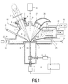
- the target plate can be additionally heated as required by an additional heater 8.
- the target material With a power density of 106 to 107 watts / cm2 in focus, the target material is over there the melting point is heated, partially evaporates, and particles 9 form in the highly supersaturated vapor phase or particles 9 evaporate directly from the surface.
- the ZnSe window 3 is kept free of any evaporation layers by an inert purge gas (arrow 10) (insert 11 with nozzles for purge gas).
- the ultrafine particles 9 formed directly above the point of impact are transported by an inert transport gas 31, which is blown onto the target surface through a nozzle 12, through a heated suction opening (arrow 13) to a deposition chamber 14, where they strike a cooled substrate electrode 15 ( Cooling 16).
- a direct current or alternating current glow discharge can optionally be ignited between the substrate electrode 15 and the counter electrode 17 (voltage supply 18), and reactive gases for CVD or PCVD can additionally be let into the deposition chamber 14.
- Transport gases and reactive gauze or gaseous reaction products are sucked off by a pump for gas disposal (arrow 19), and a pressure of about 1 to 100 hPa is maintained in the deposition chamber 14, while the pressure in the evaporator chamber 5 is about 100 to 1000 hPa (outlet pressure in the gas nozzle: some 105 Pa).
- the spot temperature is measured perpendicular to the surface of the laser beam using an infrared pyrometer 20 (viewing window 21) and readjusted, for example, via the focus positioning.
- the target 7 continuously moved computer-controlled, for example after a meander grid.
- the resulting particles are, for example, a He-Ne laser beam 22, which enters the chamber 5 through a rinsed window 23 (rinsing insert not shown here) and parallel to the target plate 7 above the heated spot (beam height above the plate, for example, adjustable via a rotatable plane-parallel plate 24 is guided in front of the window 23) and strikes a photodetector 26 through a likewise rinsed viewing window 25, detected via light scattering and thus a reduction in the intensity of the HeNe beam.
- a He-Ne laser beam 22 enters the chamber 5 through a rinsed window 23 (rinsing insert not shown here) and parallel to the target plate 7 above the heated spot (beam height above the plate, for example, adjustable via a rotatable plane-parallel plate 24 is guided in front of the window 23) and strikes a photodetector 26 through a likewise rinsed viewing window 25, detected via light scattering and thus a reduction in the intensity of the HeNe beam.
- the portion of the CO2 laser beam reflected from the target surface is either reflected back onto the focal spot by a curved spherical concave mirror 27 or absorbed in an absorber 28 (e.g. Woodsches Horn) or "swamp" for more scattering surfaces.
- the polarization of the IR laser beam is expediently circular in order to avoid anisotropies during the evaporation with a linearly polarized beam.
- a linearly polarized beam can also be used (see Fig. 3) and angles of incidence other than that shown in Fig. 1 can also be used.
- the plasma chamber (PCVD, CVD) and deposition chamber can also be arranged one after the other spatially separated from one another.
- the target plate 7 is a round "plate” which is rotatable at the angular velocity about the axis 29 shown there, the axis can also be linearly displaced parallel to the point of incidence of the laser beam .
- the point of impact is usually eccentric.
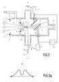
- FIG. 2 An arrangement according to the invention is shown in FIG. 2.
- the NdYAG or CO2 laser beam 1 does not strike almost vertically as in FIG. 1, but is focused in a weakly grazing incidence in the focus area into a correspondingly narrowed target nozzle 30.
- An inert (or reactive) transport gas 31 enters the target chamber 5 and flows out through the target nozzle 30 into the deposition chamber 14 and thereby transports the particles 9 formed in (and after) the nozzle to the substrate surface 15.
- the flat grazing incidence has the advantage of up to 50 times higher electric field strength on the surface compared to the vertical incidence, but of course the disadvantage of the area intensity decreasing with the angle of incidence.
- the target cone nozzle insert can be displaced in the direction of beam incidence via a linear bushing (not shown in FIG. 2) - sliding in sealing rings 4.
- a focus shift can also be achieved by a linear shift of the converging lens 2 on the beam axis.
- a He-Ne laser beam 22 is irradiated directly behind the cone nozzle opening, and it the particle formation is registered by reducing the intensity of the beam.
- the substrate electrode 15, on which the particle beam strikes, is provided with a variable temperature setting 16 (cooling or heating) and can be displaced linearly in all three spatial directions (device 6 ').
- a counter electrode 17 enables a direct or alternating voltage (voltage supply 18) to be applied between the latter and the substrate 15 and thus the formation of a glow discharge.
- reactive gauze can be introduced (not shown here) and the particles can be coated by CVD or PCVD or dissolved in the plasma and deposited on the substrate.
- the target 7 is a thin, linearly displaceable metal sheet on which the CO2 laser beam 1 in focus, slightly inclined to the surface normal, impinges, a focus adjustment by a relative displacement of the ZnSe- Converging lens (Ge converging lens) 2 is reached in the direction of the beam axis. Due to the angle between the beam axis and the target normal of a few degrees, back reflections of the laser beam and thus possible power fluctuations are avoided.
- the jet inlet window 3 (ZnSe) is also flushed from the inside with an inert flushing gas via a flushing gas nozzle insert 11 in order to avoid window coatings.
- the target 7 is arranged in the center of a three-dimensional cross piece 32.
- the focal spot temperature is measured using a pyrometer 20 Temperature checked on the back of the sheet (at the focal spot 33), and the focus is usually readjusted to maximum temperature.
- a catcher plate 34 sits opposite the target 7 in the pumping direction 19, covers almost the entire pump cross section in a version according to the invention, with the exception of a central round aperture opening, behind which the actual substrate is seated.
- a particle blowing out in the direction of the collector can also be achieved via a transport gas nozzle 35.
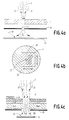
- FIGS. 4a and 4b An arrangement for embedding ultrafine particles, e.g. from BaO or Sc2O3 or SiO2, in a e.g. Tungsten layer (or other metal layer) deposited via thermal CVD is shown in FIGS. 4a and 4b. It contains an inert transport gas, e.g. Argon, indicated by arrows 31. Between a (x-y) displaceable target 7, e.g. made of SiO2, BaO or Sc2O3, and a heated substrate 15, a fixed aperture 36 is arranged with an aperture 37 for forced transport gas flow.
- a (x-y) displaceable target 7 e.g. made of SiO2, BaO or Sc2O3
- a heated substrate a fixed aperture 36 is arranged with an aperture 37 for forced transport gas flow.
- ultrafine particles are not only evaporated from the surface of the target, but the target is totally pierced by the laser beam and the continuous delivery of ultrafine particles takes place by relative movement of the target perpendicular to the stationary laser beam (focus).
- the likewise fixed aperture behind the target with an opening in the area of the laser beam means that the inert transport gas only flows out through this opening, in which ultrafine particles are currently being evaporated, and not through the one already into the target / sedimentation chamber.
- the inert transport gas 31 transferring the ultrafine particles 9 made of target material e.g. BaO, Sc2O3 then strikes a substrate 15 on which tungsten e.g. is deposited via CVD, here thermal CVD, and grows around the ultrafine particles also striking, so that a material structure of W with BaO / Sc2O3 particle embeddings is formed.
- target material e.g. BaO, Sc2O3
- alkaline earth replenishment cathodes can be produced in a single continuous process, which replaces the many previous individual steps in the production, such as powder pressing and sintering for the porous W matrix, impregnation, application of the cover layer. This makes I-cathodes accessible for mass production.
- FIG. 4c in the arrangement according to FIGS. 4a and 4b, the target 7, which incidentally can also lie loosely on the diaphragm 36, is replaced by a target made of four different layers.
- Target plates consisting of BaO (1 mm thick), CaO (0.5 mm thick) and Al2O3 (0.5 mm thick), loosely stacked on top of each other and shifted relative to the laser spot via two linear guides, for example in a meandering shape.
- these targets are relatively porous compacts.
- a target compact can also be used, which consists of a mixture of BaO: CaO: Al2O3 in a ratio of 4: 1: 1.
- the top layer can also be deposited with 4 BaO.CaO.Al2O3 targets pulled out.
- the substrate is typically peeled off, either mechanically or by selective etching, or by using a substrate on which the W-CVD + particle embedding layer does not adhere.
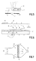
- FIG. 5 shows how target material struck by a laser beam 1 is completely removed in the direction of radiation, the major part of the beam interacting with the target and only a small part 1 ′ passing the residual target 7 ′. Edge removal is thus carried out by the laser beam relative to the target is moved along the target edge in the target edge zone (arrow 39) and, with suitable setting of the laser parameters such as power, power density and the relative speed, completely removes the target edge in each case.
- the target part that has already been removed is designated 7 ′′.
- a layer 41 of ultrafine particles (FIG. 6) or of chain-containing agglomerates 41 '(FIG. 7) is deposited on or on a porous substrate 15' from a particle stream 40 with inert carrier gas.
- the layers 41 and 41 'and the porous substrates 15' are exposed to a reactive gas, e.g. WF6 / H2, flows through (arrows 38).
- 42 means an ohmic heating winding and 43 a coil for inductive heating.
- the separation of agglomerates of ultrafine particles and the CVI solidification can also be carried out in succession.
Landscapes
- Chemical & Material Sciences (AREA)
- Metallurgy (AREA)
- Chemical Kinetics & Catalysis (AREA)
- Engineering & Computer Science (AREA)
- Materials Engineering (AREA)
- Mechanical Engineering (AREA)
- Organic Chemistry (AREA)
- General Chemical & Material Sciences (AREA)
- Health & Medical Sciences (AREA)
- Toxicology (AREA)
- Physical Or Chemical Processes And Apparatus (AREA)
- Physical Vapour Deposition (AREA)
- Chemical Vapour Deposition (AREA)
- Manufacture Of Metal Powder And Suspensions Thereof (AREA)
Claims (22)
- Procédé de fabrication de particules ultra-fines présentant des diamètres comprises entre 1 et 100 nm, qui sont fabriquées à partir d'une cible par l'intermédiaire d'évaporation par faisceau laser, caractérisé en ce que par rapport à la cible le faisceau laser est déplacé dans la zone périphérique de cible suivant le bord de cible et que dans le cas d'un ajustage convenable des paramètres laser, savoir la puissance, la densité de puissance ainsi que la vitesse relative, le bord de cible est enlevé complètement.
- Procédé selon la revendication 1, caractérisé en ce que les particules ultra-fines évaporées passent par une ouverture perceé dans la cible et le cas échéant encore par un diaphragme additionnel.
- Procédé selon la revendication 1 ou 2, caractérisé en ce qu'avant le commencement de l'enlèvement la surface de la cible est rendue rugueuse, émerisée ou oxydée.
- Procédé selon la revendication 1 ou 2, caractérisé en ce que l'on utilise comme cible un corps moulé poreux.
- Procédé selon la revendication 1, 2 ou 3, caractérisé en ce que plusieurs constituants de matériau sont évaporés en même temps pour en fabriquer des particules ultra-fines.
- Procédé selon l'une ou plusieurs des revendications 1 à 5, caractérisé en ce que la cible est chauffée directement ou indirectement.
- Procédé selon l'une ou plusieurs des revendications 1 à 6, caractérisé en ce que l'évaporation au faisceau laser à partir de la cible se produit devant, dans ou derrière le foyer d'un rayon focalisé.
- Procédé selon la revendication 7, caractérisé en ce que la focalisation est effectuée dans ou à l'extérieur d'une chambre de cible par un miroir de focalisation sphérique rincé au gaz inerte.
- Procédé selon l'une ou plusieurs des revendications 1 à 8, caractérisé en ce que sur la surface de cible le faisceau laser présente un profil de puissance constitué d'une zone d'enlèvement de matériau étroite à puissance élevée et d'une zone de chauffage plus large à puissance faible.
- Procédé selon l'une ou plusieurs des revendications 1 à 9, caractérisé en ce que les particules ultra-fines sont transférées en général à une chambre collectrice ou vers un substrat par l'intermédiaire d'un gaz de transport inerte et le cas échéant d'un dispositif de sélection de grosseur intercalé.
- Procédé selon l'une ou plusieurs des revendications 1 à 10, caractérisé en ce que les particules ultra-fines présentent une distribution de grosseur dont l'écart standard est tout au plus égal à 10% du diamètre moyen ou que seulement des particules sélectionnées présentant la distribution de grosseur y compris leurs agglomérats atteignent la chambre collectrice ou le substrat.
- Procédé selon l'une ou plusieurs des revendications 1 à 11, caractérisé en ce qu'un dosage des particules ultra-fines est effectué par l'ajustage de la densité de puissance laser sur la surface de cible, de la taille du spot de cible, de la vitesse relative entre la cible et le faisceau laser, de la pression totale régnant dans la chambre de cible et/ou qu'est effectuée une division du débit du courant de gaz porteur.
- Procédé selon la revendication 12, caractérisé en ce que les valeurs mentionnées sont maintenues constantes lors de la durée du procédé.
- Procédé selon la revendication 12 ou 13, caractérisé en ce que la pression totale dans la chambre de cible est ajustée à un niveau tellement bas, que le maximum de la distribution de grosseurs coïncide avec la grosseur des particules à sélectionner.
- Procédé selon l'une ou plusieurs des revendications 1 à 14, caractérisé en ce que les particules ultra-fines de charges présentant le même signe sont chargées et que dans le cas de particules oxydiques respectivement d'isolants elles sont revêtues avantageusement d'abord d'une couche superficielle mince, d'une épaisseur de quelques monocouches seulement, électriquement conductrice respectivement métallique.
- Procédé selon la revendication 15, caractérisé en ce que le constituant de matériau entourant les particules ultra-fines est un matériau dont la solubilité solide dans le matériau de particule est négligemment faible.
- Procédé selon l'une ou plusieurs des revendications 1 à 16, caractérisé en ce que pour la fabrication de matériaux à un ou à plusieurs constituants ou pour la fabrication de corps moulés les substrats sont revêtus de particules ultra-fines.
- Procédé selon la revendication 17, caractérisé en ce que lors du revêtement du substrat les particules ultra-fines sont déposées conjointement avec un autre constituant de matériau, ledit constituant étant déposé par dépôt réactif à partir d'une phase gazeuse supplémentaire, c'est-à-dire par CVD, par CVD assisté de plasma ou CVD induit au laser.
- Procédé selon la revendication 17, caractérisé en ce que d'abord les particules ultra-fines sont déposées et que subséquemment est mis en oeuvre un procédé de solidification indiqué par CVI = chemical vapour infiltration (infiltration chimique en phase vapeur).
- Procédé selon la revendication 17, caractérisé en ce que les substrats sont revêtus de particules ultra-fines provenant de plusieurs matériaux, les particules ultra-fines individuelles étant constituées soit d'un seul matériau ou de plusieurs matériaux et que subséquemment les particules sont frittées par un traitement thermique et compactées de manière à être poreuses.
- Procédé selon la revendication 17, caractérisé en ce que sans solidification supplémentaire les particules ultra-fines sont appliquées en forme de structures de chaîne et d'extrémités de chaîne s'adhérant à la surface de substrat.
- Procédé selon les revendications 17, 18 ou 19, caractérisé en ce que la cible est constituée de 4BaO . CaO . Al₂O₃, que dans la dernière phase de revêtement des particules ultra-fines sont évaporées à partir d'une autre cible en Sc₂O₃ et que l'autre constituant de matériau destiné à solidifier la structure poreuse est le tungstène qui est déposé à partir de WF₆/H₂ ou d'une autre source gazeuse W par l'intermédiaire d'un procédé de PCVD, de CVD ou de CVI.
Applications Claiming Priority (2)
| Application Number | Priority Date | Filing Date | Title |
|---|---|---|---|
| DE4000690A DE4000690A1 (de) | 1990-01-12 | 1990-01-12 | Verfahren zum herstellen von ultrafeinen partikeln und deren verwendung |
| DE4000690 | 1990-01-12 |
Publications (2)
| Publication Number | Publication Date |
|---|---|
| EP0442163A1 EP0442163A1 (fr) | 1991-08-21 |
| EP0442163B1 true EP0442163B1 (fr) | 1994-07-27 |
Family
ID=6397921
Family Applications (1)
| Application Number | Title | Priority Date | Filing Date |
|---|---|---|---|
| EP90203467A Expired - Lifetime EP0442163B1 (fr) | 1990-01-12 | 1990-12-21 | Méthode de production de particules ultrafines et leur utilisation |
Country Status (4)
| Country | Link |
|---|---|
| US (1) | US5254832A (fr) |
| EP (1) | EP0442163B1 (fr) |
| JP (1) | JPH04214859A (fr) |
| DE (2) | DE4000690A1 (fr) |
Cited By (1)
| Publication number | Priority date | Publication date | Assignee | Title |
|---|---|---|---|---|
| US8343415B2 (en) | 2007-01-15 | 2013-01-01 | Saint-Gobain Ceramics & Plastics, Inc. | Ceramic particulate material and processes for forming same |
Families Citing this family (53)
| Publication number | Priority date | Publication date | Assignee | Title |
|---|---|---|---|---|
| DE4000885A1 (de) * | 1990-01-13 | 1991-07-18 | Philips Patentverwaltung | Mehrkomponentige submikroskopische partikel und verfahren zu ihrer herstellung |
| DE4207220A1 (de) * | 1992-03-07 | 1993-09-09 | Philips Patentverwaltung | Festkoerperelement fuer eine thermionische kathode |
| US5850089A (en) * | 1992-03-13 | 1998-12-15 | American Research Corporation Of Virginia | Modulated-structure of PZT/PT ferroelectric thin films for non-volatile random access memories |
| US5320882A (en) * | 1992-04-22 | 1994-06-14 | General Electric Company | Laser ablative particulate composite |
| JP3255469B2 (ja) * | 1992-11-30 | 2002-02-12 | 三菱電機株式会社 | レーザ薄膜形成装置 |
| GB2300000A (en) * | 1992-11-30 | 1996-10-23 | Mitsubishi Electric Corp | Thin film forming using laser and activated oxidising gas |
| WO1994026425A1 (fr) * | 1993-05-17 | 1994-11-24 | Mcdonnell Douglas Corporation | Procede de depot par onde d'absorption laser |
| US6270861B1 (en) * | 1994-07-21 | 2001-08-07 | Ut, Battelle Llc | Individually controlled environments for pulsed addition and crystallization |
| DE19510318B4 (de) * | 1995-03-22 | 2004-02-19 | Deutsches Zentrum für Luft- und Raumfahrt e.V. | Verfahren und Vorrichtung zur Herstellung epitaktischer Schichten |
| US5612099A (en) * | 1995-05-23 | 1997-03-18 | Mcdonnell Douglas Corporation | Method and apparatus for coating a substrate |
| US5814152A (en) * | 1995-05-23 | 1998-09-29 | Mcdonnell Douglas Corporation | Apparatus for coating a substrate |
| US5593742A (en) * | 1995-08-24 | 1997-01-14 | The United States Of America As Represented By The Secretary Of The Army | Fabrication of silicon microclusters and microfilaments |
| EP0792688A1 (fr) * | 1996-03-01 | 1997-09-03 | Dow Corning Corporation | Nanoparticules d'alliages à l'oxyde de silicium |
| US6017630A (en) * | 1996-05-22 | 2000-01-25 | Research Development Corporation | Ultrafine particle and production method thereof, production method of ultrafine particle bonded body, and fullerene and production method thereof |
| US6952504B2 (en) * | 2001-12-21 | 2005-10-04 | Neophotonics Corporation | Three dimensional engineering of planar optical structures |
| US6120857A (en) * | 1998-05-18 | 2000-09-19 | The Regents Of The University Of California | Low work function surface layers produced by laser ablation using short-wavelength photons |
| JP2963993B1 (ja) * | 1998-07-24 | 1999-10-18 | 工業技術院長 | 超微粒子成膜法 |
| US6533908B1 (en) | 1998-08-26 | 2003-03-18 | Fraunhofer-Gesellschaft Zur Forderung Der Angewandten Forschung E.V. | Device and method for coating substrates in a vacuum utilizing an absorber electrode |
| EP1117852B1 (fr) | 1998-08-26 | 2002-07-31 | Fraunhofer-Gesellschaft Zur Förderung Der Angewandten Forschung E.V. | Procede et dispositif pour enduire des substrats sous vide |
| US20030020768A1 (en) * | 1998-09-30 | 2003-01-30 | Renn Michael J. | Direct write TM system |
| US20040197493A1 (en) * | 1998-09-30 | 2004-10-07 | Optomec Design Company | Apparatus, methods and precision spray processes for direct write and maskless mesoscale material deposition |
| US8110247B2 (en) | 1998-09-30 | 2012-02-07 | Optomec Design Company | Laser processing for heat-sensitive mesoscale deposition of oxygen-sensitive materials |
| JP2002528744A (ja) | 1998-09-30 | 2002-09-03 | ボード・オブ・コントロール・オブ・ミシガン・テクノロジカル・ユニバーシティ | 非原子粒子のレーザガイドされる操作 |
| US7108894B2 (en) * | 1998-09-30 | 2006-09-19 | Optomec Design Company | Direct Write™ System |
| US7938079B2 (en) | 1998-09-30 | 2011-05-10 | Optomec Design Company | Annular aerosol jet deposition using an extended nozzle |
| US7045015B2 (en) | 1998-09-30 | 2006-05-16 | Optomec Design Company | Apparatuses and method for maskless mesoscale material deposition |
| US6636676B1 (en) * | 1998-09-30 | 2003-10-21 | Optomec Design Company | Particle guidance system |
| US7294366B2 (en) * | 1998-09-30 | 2007-11-13 | Optomec Design Company | Laser processing for heat-sensitive mesoscale deposition |
| AU6431199A (en) * | 1998-10-12 | 2000-05-01 | Regents Of The University Of California, The | Laser deposition of thin films |
| JP4564113B2 (ja) * | 1998-11-30 | 2010-10-20 | 株式会社東芝 | 微粒子膜形成方法 |
| CN100377239C (zh) * | 1999-03-15 | 2008-03-26 | 松下电器产业株式会社 | 信息记录媒体及其制造方法 |
| US6335208B1 (en) * | 1999-05-10 | 2002-01-01 | Intersil Americas Inc. | Laser decapsulation method |
| JP4545902B2 (ja) * | 2000-08-25 | 2010-09-15 | キヤノン株式会社 | 成膜方法 |
| EP1333935A4 (fr) * | 2000-10-17 | 2008-04-02 | Nanogram Corp | Formation de rev tement par d p t r actif |
| EP1422313A1 (fr) * | 2002-11-05 | 2004-05-26 | Theva Dünnschichttechnik GmbH | Dispositif et méthode de depot en phase vapeur sous vide d'un matériau de revêtement avec remplissage de matériau automatique |
| US20060280866A1 (en) * | 2004-10-13 | 2006-12-14 | Optomec Design Company | Method and apparatus for mesoscale deposition of biological materials and biomaterials |
| US7938341B2 (en) | 2004-12-13 | 2011-05-10 | Optomec Design Company | Miniature aerosol jet and aerosol jet array |
| US7674671B2 (en) | 2004-12-13 | 2010-03-09 | Optomec Design Company | Aerodynamic jetting of aerosolized fluids for fabrication of passive structures |
| US20090029070A1 (en) * | 2004-12-17 | 2009-01-29 | Universidad De Vigo | Method of producing nanowires in ambient conditions and nanowires thus produced |
| EP1871151B1 (fr) * | 2006-06-21 | 2015-01-14 | Ecole Polytechnique | Procédé et dispositif de génération d'un faisceau d'électrons quasi mono-énergétiques stable et réglable |
| US20090014423A1 (en) * | 2007-07-10 | 2009-01-15 | Xuegeng Li | Concentric flow-through plasma reactor and methods therefor |
| US8471170B2 (en) | 2007-07-10 | 2013-06-25 | Innovalight, Inc. | Methods and apparatus for the production of group IV nanoparticles in a flow-through plasma reactor |
| US8968438B2 (en) | 2007-07-10 | 2015-03-03 | Innovalight, Inc. | Methods and apparatus for the in situ collection of nucleated particles |
| TWI482662B (zh) | 2007-08-30 | 2015-05-01 | Optomec Inc | 機械上一體式及緊密式耦合之列印頭以及噴霧源 |
| TWI538737B (zh) | 2007-08-31 | 2016-06-21 | 阿普托麥克股份有限公司 | 材料沉積總成 |
| US8887658B2 (en) | 2007-10-09 | 2014-11-18 | Optomec, Inc. | Multiple sheath multiple capillary aerosol jet |
| FI20070889L (fi) * | 2007-11-21 | 2009-05-22 | Picodeon Ltd Oy | Pinnankäsittelymenetelmä |
| EP2313230A4 (fr) * | 2008-07-09 | 2017-03-08 | FEI Company | Procédé et appareil d'usinage laser |
| FR2974021B1 (fr) * | 2011-04-18 | 2013-04-05 | Commissariat Energie Atomique | Procede pour la preparation de particules metalliques |
| JP6014669B2 (ja) * | 2011-08-03 | 2016-10-25 | コーニンクレッカ フィリップス エヌ ヴェKoninklijke Philips N.V. | バリウム−スカンジウム酸化物ディスペンサカソード用の標的 |
| CN104532194B (zh) * | 2014-12-29 | 2017-05-10 | 深圳大学 | 激光沉积薄膜制备装置 |
| WO2016130709A1 (fr) | 2015-02-10 | 2016-08-18 | Optomec, Inc. | Fabrication de structures tridimensionnelles par durcissement en vol d'aérosols |
| KR20200087196A (ko) | 2017-11-13 | 2020-07-20 | 옵토멕 인코포레이티드 | 에어로졸 스트림의 셔터링 |
Family Cites Families (5)
| Publication number | Priority date | Publication date | Assignee | Title |
|---|---|---|---|---|
| EP0143122A3 (fr) * | 1983-08-26 | 1987-02-04 | Shin-Etsu Chemical Co., Ltd. | Poudre ultrafine de carbure de silicium, procédé pour sa préparation et corps fritté obtenu à partir de celle-ci |
| JPS6254005A (ja) * | 1985-09-02 | 1987-03-09 | Hitachi Ltd | 超微粒子の製造方法 |
| JPS63227766A (ja) * | 1986-10-27 | 1988-09-22 | Hitachi Ltd | 超微粒子膜の形成方法 |
| DE3800680A1 (de) * | 1988-01-13 | 1989-07-27 | Leyendecker Toni | Verfahren und vorrichtung zur beschichtung eines substrates |
| DE3824273A1 (de) * | 1988-07-16 | 1990-01-18 | Philips Patentverwaltung | Verfahren zur herstellung von festkoerpern |
-
1990
- 1990-01-12 DE DE4000690A patent/DE4000690A1/de not_active Withdrawn
- 1990-12-21 EP EP90203467A patent/EP0442163B1/fr not_active Expired - Lifetime
- 1990-12-21 DE DE59006613T patent/DE59006613D1/de not_active Expired - Fee Related
-
1991
- 1991-01-08 US US07/642,241 patent/US5254832A/en not_active Expired - Fee Related
- 1991-01-14 JP JP3016102A patent/JPH04214859A/ja active Pending
Cited By (1)
| Publication number | Priority date | Publication date | Assignee | Title |
|---|---|---|---|---|
| US8343415B2 (en) | 2007-01-15 | 2013-01-01 | Saint-Gobain Ceramics & Plastics, Inc. | Ceramic particulate material and processes for forming same |
Also Published As
| Publication number | Publication date |
|---|---|
| EP0442163A1 (fr) | 1991-08-21 |
| JPH04214859A (ja) | 1992-08-05 |
| DE4000690A1 (de) | 1991-07-18 |
| US5254832A (en) | 1993-10-19 |
| DE59006613D1 (de) | 1994-09-01 |
Similar Documents
| Publication | Publication Date | Title |
|---|---|---|
| EP0442163B1 (fr) | Méthode de production de particules ultrafines et leur utilisation | |
| EP0535019B1 (fr) | Procede et dispositif d'enduction de substrats | |
| DE4340752C2 (de) | Vorrichtung zur Herstellung einer gleichförmigen Dünnschicht auf einer großen Substratfläche unter Verwendung eines Lasers | |
| DE69407734T2 (de) | Verfahren zur Herstellung diamantartiger Beschichtungen | |
| DE19726443C2 (de) | Verfahren zur Oberflächenvergütung innerer Oberflächen von Hohlkörpern und Vorrichtung zur Durchführung des Verfahrens | |
| DE69028662T2 (de) | Verfahren und Vorrichtung zum Laseraufdampfen | |
| DE4217450C3 (de) | Ionenbedampfungsverfahren und Vorrichtung | |
| DE3610298C2 (fr) | ||
| DE3611492A1 (de) | Verfahren und vorrichtung zum beschichten von werkzeugen fuer die zerspanungs- und umformtechnik mit hartstoffschichten | |
| DE19935053A1 (de) | Verfahren zum Bilden eines Films aus ultrafeinen Teilchen | |
| DE2006075A1 (de) | Verfahren und Vorrichtung zum Er?eugen feiner Pulver eines Metalls oder einer» Legierung | |
| DE4016352A1 (de) | Laser-aufdampfeinrichtung | |
| EP0437890A1 (fr) | Méthode de production de matériaux multicomposants | |
| DE3785295T2 (de) | Verfahren zur herstellung eines films aus ultrafeinen teilchen. | |
| EP1558782A2 (fr) | Dispositif et procede de depot en phase vapeur d'un materiau de revetement | |
| DE3925085C1 (fr) | ||
| EP0425623A1 (fr) | Procede pour appliquer un materiau ceramique. | |
| DE69922479T2 (de) | Verbesserte Stranggusskikille | |
| EP1161570B1 (fr) | Procede pour recouvrir un corps support d'un materiau a base de se-fe-n magnetique dur, par projection au plasma | |
| DE4408052C1 (de) | Verwendung einer Apparatur zur Clusterstrahlerzeugung und zur Oberflächenbeschichtung eines Substrats | |
| DE19648749A1 (de) | Magnetisches Dünnfilm-Aufzeichnungsmedium und Verfahren zu seiner Herstellung | |
| DE19538110A1 (de) | Verfahren und Vorrichtung zum Erzeugen dünner Schichten aus diamantartigem Kohlenstoff auf einem Substrat nach Beschluß eines Targets mit gepulsten Elektronenstrahlen (Pseudofunkenelektronenstrahlen) | |
| DE4035073C1 (fr) | ||
| DE19525159A1 (de) | Verfahren zur Herstellung eines ultrafeinen Pulvers und einer Beschichtung | |
| DE4226864C2 (de) | Einrichtung zum Beschichten eines Substratkörpers mit einem ablatierbaren Material |
Legal Events
| Date | Code | Title | Description |
|---|---|---|---|
| PUAI | Public reference made under article 153(3) epc to a published international application that has entered the european phase |
Free format text: ORIGINAL CODE: 0009012 |
|
| AK | Designated contracting states |
Kind code of ref document: A1 Designated state(s): DE FR GB |
|
| 17P | Request for examination filed |
Effective date: 19920221 |
|
| 17Q | First examination report despatched |
Effective date: 19930608 |
|
| GRAA | (expected) grant |
Free format text: ORIGINAL CODE: 0009210 |
|
| AK | Designated contracting states |
Kind code of ref document: B1 Designated state(s): DE FR GB |
|
| REF | Corresponds to: |
Ref document number: 59006613 Country of ref document: DE Date of ref document: 19940901 |
|
| GBT | Gb: translation of ep patent filed (gb section 77(6)(a)/1977) |
Effective date: 19941017 |
|
| ET | Fr: translation filed | ||
| PLBE | No opposition filed within time limit |
Free format text: ORIGINAL CODE: 0009261 |
|
| STAA | Information on the status of an ep patent application or granted ep patent |
Free format text: STATUS: NO OPPOSITION FILED WITHIN TIME LIMIT |
|
| REG | Reference to a national code |
Ref country code: FR Ref legal event code: CD |
|
| 26N | No opposition filed | ||
| PGFP | Annual fee paid to national office [announced via postgrant information from national office to epo] |
Ref country code: FR Payment date: 19961217 Year of fee payment: 7 |
|
| PGFP | Annual fee paid to national office [announced via postgrant information from national office to epo] |
Ref country code: DE Payment date: 19970221 Year of fee payment: 7 |
|
| PGFP | Annual fee paid to national office [announced via postgrant information from national office to epo] |
Ref country code: GB Payment date: 19971201 Year of fee payment: 8 |
|
| PG25 | Lapsed in a contracting state [announced via postgrant information from national office to epo] |
Ref country code: FR Free format text: THE PATENT HAS BEEN ANNULLED BY A DECISION OF A NATIONAL AUTHORITY Effective date: 19971231 |
|
| PG25 | Lapsed in a contracting state [announced via postgrant information from national office to epo] |
Ref country code: DE Free format text: LAPSE BECAUSE OF NON-PAYMENT OF DUE FEES Effective date: 19980901 |
|
| REG | Reference to a national code |
Ref country code: FR Ref legal event code: ST |
|
| PG25 | Lapsed in a contracting state [announced via postgrant information from national office to epo] |
Ref country code: GB Free format text: LAPSE BECAUSE OF NON-PAYMENT OF DUE FEES Effective date: 19981221 |
|
| GBPC | Gb: european patent ceased through non-payment of renewal fee |
Effective date: 19981221 |