EP0434176B1 - Schloss-Schlüssel-Kombination - Google Patents
Schloss-Schlüssel-Kombination Download PDFInfo
- Publication number
- EP0434176B1 EP0434176B1 EP90250332A EP90250332A EP0434176B1 EP 0434176 B1 EP0434176 B1 EP 0434176B1 EP 90250332 A EP90250332 A EP 90250332A EP 90250332 A EP90250332 A EP 90250332A EP 0434176 B1 EP0434176 B1 EP 0434176B1
- Authority
- EP
- European Patent Office
- Prior art keywords
- key
- lock
- reading head
- key combination
- antenna
- Prior art date
- Legal status (The legal status is an assumption and is not a legal conclusion. Google has not performed a legal analysis and makes no representation as to the accuracy of the status listed.)
- Expired - Lifetime
Links
Images
Classifications
-
- G—PHYSICS
- G07—CHECKING-DEVICES
- G07C—TIME OR ATTENDANCE REGISTERS; REGISTERING OR INDICATING THE WORKING OF MACHINES; GENERATING RANDOM NUMBERS; VOTING OR LOTTERY APPARATUS; ARRANGEMENTS, SYSTEMS OR APPARATUS FOR CHECKING NOT PROVIDED FOR ELSEWHERE
- G07C9/00—Individual registration on entry or exit
- G07C9/00174—Electronically operated locks; Circuits therefor; Nonmechanical keys therefor, e.g. passive or active electrical keys or other data carriers without mechanical keys
- G07C9/00944—Details of construction or manufacture
Definitions
- the invention relates to a lock and key combination according to the preamble of claim 1.
- Combinations of this type are known in practice, the key being insertable in a conventional manner into a locking cylinder and its coding consisting of notches and profiles being mechanically scannable there by the tumbler or the locking pin.
- electronics are arranged in the key ring and, for example, in the longitudinal edge of the key shaft there is an antenna in the form of a coil, which cooperates with a reading head which surrounds the locking cylinder or is arranged therein. Energy and information can be exchanged via the antenna in the key or the corresponding antenna in the reading head, so that the locking authorization can be checked not only mechanically but also electronically.
- Such lock-key combinations have the advantage that not only can this locking authorization be checked in principle, but that there is also the possibility of recognizing the use of the lock via appropriate computers and display units, locking the actuation and storing individual actuations, so that to create an electronic locking control and information system with the highest security requirements.
- the invention has for its object to simplify and improve the production of this lock-key combination.
- This object is achieved in that the key-side antenna in one of the free Narrow sides of the key ring is provided and that the reading head is spatially separated from the lock cylinder.
- the advantage of the solution according to the invention is that it is much less complex to arrange the corresponding key-side antenna in the raid instead of previously in the long side of the key shaft and that this also simplifies the arrangement of the reading head.
- This read head which is spatially separate from the lock cylinder, can be provided on the lock itself or adjacent to it, in which case, of course, there is an electrical connection to the lock.
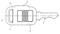
- the invention will be explained below with reference to the drawing, which schematically shows a key with a key shaft 1 and the key ring 2.
- the individual profiles of the key shaft are not shown in the drawing and only the notch on the key face is indicated.
- the key ring usually has two side surfaces, which serve as gripping surfaces, and three free narrow sides, which are denoted by 4 in the figure.
- the fourth narrow side accommodates the key shaft and is therefore not referred to as the free narrow side in this context.
- the key-side antenna is now arranged in one of the free narrow sides of the key ring, this being represented by 3 in the figure.
- This key is now handled in such a way that, for example, first this key-side antenna 3 is placed on the reading head, this being done contactlessly, so that no wear occurs here and thus the energy and information transmission can take place.
- the electronic coding of the key is evaluated and then, as usual, the key with the key shaft is inserted into the locking cylinder.
- the locking authorization is then given or withdrawn on the basis of the electronic control carried out beforehand, and this means that if the authorization is granted, the locking cylinder itself can be actuated in a conventional manner by correspondingly turning the key, so that the lock is opened is possible.
Landscapes
- Engineering & Computer Science (AREA)
- Manufacturing & Machinery (AREA)
- Physics & Mathematics (AREA)
- General Physics & Mathematics (AREA)
- Lock And Its Accessories (AREA)
- Input Circuits Of Receivers And Coupling Of Receivers And Audio Equipment (AREA)
Description
- Die Erfindung betrifft eine Schloß-Schlüssel-Kombination gemäß dem Oberbegriff des Anspruchs 1.
- Aus der Praxis sind derartige Kombinationen bekannt, wobei der Schlüssel in üblicher Weise in einen Schließzylinder einführbar ist und dort dessen aus Kerben und Profilen bestehende Codierung mechanisch durch die Zuhaltung bzw. den Sperrstift abtastbar ist. Darüber hinaus ist bei derartigen Schlüsseln in der Schlüsselraide eine Elektronik angeordnet und bspw. in der Längskante des Schlüsselschaftes befindet sich eine Antenne in Form einer Spule, die mit einem Lesekopf zusammenarbeitet, der den Schließzylinder umgibt bzw. in diesem angeordnet ist. Über die Antenne im Schlüssel bzw. die entsprechende Antenne im Lesekopf kann ein Energie- und Informationsaustausch erfolgen, so daß die Schließberechtigung nicht nur mechanisch, sondern auch elektronisch überprüfbar ist. Derartige Schloß-Schlüssel-Kombinationen haben den Vorteil, daß nicht nur diese Schließberechtigung grundsätzlich überprüfbar ist, sondern daß auch die Möglichkeit besteht, über entsprechende Rechner und Anzeigereinheiten die Benutzung des Schlosses zu erkennen, die Betätigung zu sperren und einzelne Betätigungen zu speichern, so daß damit insgesamt ein elektronisches Schließ-Kontroll- und Informationssystem geschaffen wird mit höchsten Sicherheitsanforderungen.
- Der Erfindung liegt die Aufgabe zugrunde, die Herstellung dieser Schloß-Schlüssel-Kombination zu vereinfachen und zu verbessern.
- Gelöst wird diese Aufgabe erfindungsgemäß dadurch, daß die schlüsselseitige Antenne in einer der freien Schmalseiten der Schlüsselraide vorgesehen ist und daß der Lesekopf räumlich getrennt vom Schließzylinder angeordnet ist.
- Der Vorteil der erfindungsgemäßen Lösung liegt darin, daß es wesentlich weniger aufwendig ist, die entsprechende schlüsselseitige Antenne in der Raide anzuordnen anstatt bisher in der Längsseite des Schlüsselschaftes und daß sich damit auch Vereinfachungen für die Anordnung des Lesekopfes ergeben. Dieser Lesekopf, der räumlich getrennt vom Schließzylinder ist, kann am Schloß selbst vorgesehen sein oder benachbart dazu, wobei selbstverständlich dann eine elektrische Verbindung zum Schloß besteht.
- Darüber hinaus ergibt sich die Möglichkeit, den Schlüssel zweiteilig zu fertigen, und zwar einerseits die Schlüsselraide und zum anderen den Schlüsselschaft, so daß eine Vielzahl von mechanisch/elektronisch codierten Schlüsseln in einfacher Weise zusammengestellt werden können.
- Die Erfindung soll nachfolgend anhand der Zeichnung erläutert werden, wobei diese schematisch einen Schlüssel zeigt mit einem Schlüsselschaft 1 und der Schlüsselraide 2. Nicht dargestellt sind in der Zeichnung die einzelnen Profilierungen des Schlüsselschaftes und angedeutet ist lediglich die Kerbung an der Schlüsselbrust. Die Schlüsselraide weist üblicherweise zwei Seitenflächen auf, die als Grifflächen dienen, sowie drei freie Schmalseiten, die in der Figur mit 4 bezeichnet sind. Die vierte Schmalseite nimmt den Schlüsselschaft auf und wird daher in diesem Zusammenhang nicht als freie Schmalseite bezeichnet.
- Erfindungsgemäß ist nun die schlüsselseitige Antenne in einer der freien Schmalseiten der Schlüsselraide angeordnet, wobei dies in der Figur mit 3 dargestellt ist.
- Die Handhabung dieses Schlüssels erfolgt nun so, daß bspw. zunächst diese schlüsselseitige Antenne 3 an den Lesekopf angelegt wird, wobei dies kontaktlos erfolgt, so daß hier kein Verschleiß auftritt und damit die Energie- und Informationsübertragung erfolgen kann. Auf diese Weise wird die elektronische Codierung des Schlüssels ausgewertet und anschließend wird, wie üblich, der Schlüssel mit dem Schlüsselschaft in den Schließzylinder eingeführt. Die Schließberechtigung wird dann aufgrund der vorher durchgeführten elektronischen Kontrolle gegeben bzw. entzogen, und dies bedeutet, daß dann, wenn die Berechtigung erteilt ist, der Schließzylinder durch entsprechende Drehung des Schlüssels selbst in üblicher Weise betätigt werden kann, so daß damit eine Öffnung des Schlosses möglich ist.
Claims (2)
- Schloß-Schlüssel-Kombination mit einem Schlüssel, dessen Schaft (1) eine aus Kerben und Profilen bestehende Codierung aufweist, die mechanisch vom im Schloß angeordneten Schließzylinder abtastbar ist und in dessen Raide (2) eine Elektronik angeordnet ist, deren Codierung von einem dem Schloß zugeordneten Lesekopf prüfbar ist, wobei die Energie- und Informationsübertragung über im Lesekopf bzw. Schlüssel angeordnete Antennen (3) erfolgt,
dadurch gekennzeichnet,
daß die schlüsselseitige Antenne (3) in einer der freien Schmalseiten (4) der Schlüsselraide vorgesehen ist und der Lesekopf räumlich getrennt vom Schließzylinder angeordnet ist. - Schloß-Schlüssel-Kombination nach Anspruch 1,
dadurch gekennzeichnet,
daß der Schlüsselschaft (1) in diese Schlüsselraide (2) einsetzbar und mit dieser fest verbindbar ist.
Priority Applications (1)
| Application Number | Priority Date | Filing Date | Title |
|---|---|---|---|
| AT90250332T ATE102681T1 (de) | 1989-12-22 | 1990-12-21 | Schloss-schluessel-kombination. |
Applications Claiming Priority (2)
| Application Number | Priority Date | Filing Date | Title |
|---|---|---|---|
| DE8915242U DE8915242U1 (de) | 1989-12-22 | 1989-12-22 | Schloß-Schlüssel-Kombination |
| DE8915242U | 1989-12-22 |
Publications (2)
| Publication Number | Publication Date |
|---|---|
| EP0434176A1 EP0434176A1 (de) | 1991-06-26 |
| EP0434176B1 true EP0434176B1 (de) | 1994-03-09 |
Family
ID=6845871
Family Applications (1)
| Application Number | Title | Priority Date | Filing Date |
|---|---|---|---|
| EP90250332A Expired - Lifetime EP0434176B1 (de) | 1989-12-22 | 1990-12-21 | Schloss-Schlüssel-Kombination |
Country Status (3)
| Country | Link |
|---|---|
| EP (1) | EP0434176B1 (de) |
| AT (1) | ATE102681T1 (de) |
| DE (2) | DE8915242U1 (de) |
Families Citing this family (1)
| Publication number | Priority date | Publication date | Assignee | Title |
|---|---|---|---|---|
| DE19821203C1 (de) * | 1998-05-12 | 1999-10-28 | Keso Gmbh Salzburg | Schließvorrichtung |
Family Cites Families (3)
| Publication number | Priority date | Publication date | Assignee | Title |
|---|---|---|---|---|
| CH664595A5 (de) * | 1984-03-15 | 1988-03-15 | Bauer Kaba Ag | Elektronisch-mechanischer flachschluessel. |
| JPH0718280B2 (ja) * | 1987-10-27 | 1995-03-01 | 本田技研工業株式会社 | キー装置 |
| ES2010274A6 (es) * | 1988-06-01 | 1989-11-01 | Talleres Escoriaza Sa | Llave electronica. |
-
1989
- 1989-12-22 DE DE8915242U patent/DE8915242U1/de not_active Expired - Lifetime
-
1990
- 1990-12-21 DE DE90250332T patent/DE59004913D1/de not_active Expired - Fee Related
- 1990-12-21 EP EP90250332A patent/EP0434176B1/de not_active Expired - Lifetime
- 1990-12-21 AT AT90250332T patent/ATE102681T1/de active
Also Published As
| Publication number | Publication date |
|---|---|
| DE8915242U1 (de) | 1990-04-05 |
| DE59004913D1 (de) | 1994-04-14 |
| EP0434176A1 (de) | 1991-06-26 |
| ATE102681T1 (de) | 1994-03-15 |
Similar Documents
| Publication | Publication Date | Title |
|---|---|---|
| EP1327043B1 (de) | Elektronisches verschlusssystem | |
| EP0188253A1 (de) | Einrichtung zur kontaktlosen Kopplung der Steuerungs- und Leistungsströme zwischen der Elektronik am Schliesszylinder und der Elektronik im Schlüssel bei einer elektronisch/mechanischen Schliesseinrichtung | |
| EP0974719A2 (de) | Schloss, insbesondere für eine Schliessanlage | |
| DE3731301A1 (de) | Kode-karte mit kodierten sicherungsmitteln | |
| DE3507871A1 (de) | Programmierbarer und mit datenverarbeitungsmitteln interaktiv kommunizierfaehiger elektronisch-mechanischer wendeflachschluessel | |
| EP0600194B1 (de) | Zutrittskontrollanlage | |
| EP0224607B1 (de) | Schliessvorrichtung mit elektronischem Identifizierungssystem | |
| DE3331357C2 (de) | ||
| DE2421997A1 (de) | Kombinationsschloss | |
| DE2063292C3 (de) | Codierverfahren und Codiertastatur zur Durchführung des Verfahrens | |
| EP0803623A1 (de) | Schliesseinrichtung für Fahrzeuge mit einem codierten elektronischen Schloss sowie Vorrichtung zur Codierung des Schlüssels | |
| EP0911466A2 (de) | Verschliessfreie programmierbare elektronische Schliessvorrichtung | |
| DE3707201A1 (de) | Doppelschliesszylinder | |
| DE19749081C2 (de) | Elektronisch-mechanisches Schließsystem | |
| EP0434176A1 (de) | Schloss-Schlüssel-Kombination | |
| EP1736622A1 (de) | Knaufzylinder | |
| DE10225368C1 (de) | Schließzylinder mit kontaktloser Übertragung eines Signals | |
| DE2635180B2 (de) | Verfahren zur elektronisch gesteuerten Freigabe von Tür-, Safe- und Funktionsschlössern unter Verwendung elektronisch codierter Schlüssel sowie Schaltungsanordnung zur Durchführung des Verfahrens | |
| DE9217524U1 (de) | Doppelschließzylinder | |
| DE3012349A1 (de) | Vorrichtung, welche mit einem oder mehreren schloessern ausgeruestet ist | |
| DE10049085A1 (de) | Elektronisches Verschlußsystem | |
| DE69024175T2 (de) | Magnetischer Schlüssel für Schlösser mit Zugangskontrolle | |
| DE2831088C2 (de) | Elektromechanische Sicherheitsschaltung mit einem Codierschalter | |
| DE19937845A1 (de) | Sicherheitsschließbausatz | |
| DE2815462C2 (de) | Anordnung zum unterschiedlichen Betätigen von Schließ- und/oder sonstigen Auswerteeinrichtungen durch optische Signale |
Legal Events
| Date | Code | Title | Description |
|---|---|---|---|
| PUAI | Public reference made under article 153(3) epc to a published international application that has entered the european phase |
Free format text: ORIGINAL CODE: 0009012 |
|
| AK | Designated contracting states |
Kind code of ref document: A1 Designated state(s): AT BE CH DE ES FR GB IT LI NL SE |
|
| 17P | Request for examination filed |
Effective date: 19920211 |
|
| 17Q | First examination report despatched |
Effective date: 19930701 |
|
| GRAA | (expected) grant |
Free format text: ORIGINAL CODE: 0009210 |
|
| AK | Designated contracting states |
Kind code of ref document: B1 Designated state(s): AT BE CH DE ES FR GB IT LI NL SE |
|
| PG25 | Lapsed in a contracting state [announced via postgrant information from national office to epo] |
Ref country code: IT Free format text: LAPSE BECAUSE OF FAILURE TO SUBMIT A TRANSLATION OF THE DESCRIPTION OR TO PAY THE FEE WITHIN THE PRE;WARNING: LAPSES OF ITALIAN PATENTS WITH EFFECTIVE DATE BEFORE 2007 MAY HAVE OCCURRED AT ANY TIME BEFORE 2007. THE CORRECT EFFECTIVE DATE MAY BE DIFFERENT FROM THE ONE RECORDED.SCRIBED TIME-LIMIT Effective date: 19940309 Ref country code: GB Effective date: 19940309 Ref country code: FR Free format text: THE PATENT HAS BEEN ANNULLED BY A DECISION OF A NATIONAL AUTHORITY Effective date: 19940309 Ref country code: ES Free format text: THE PATENT HAS BEEN ANNULLED BY A DECISION OF A NATIONAL AUTHORITY Effective date: 19940309 Ref country code: SE Free format text: THE PATENT HAS BEEN ANNULLED BY A DECISION OF A NATIONAL AUTHORITY Effective date: 19940309 |
|
| REF | Corresponds to: |
Ref document number: 102681 Country of ref document: AT Date of ref document: 19940315 Kind code of ref document: T |
|
| REF | Corresponds to: |
Ref document number: 59004913 Country of ref document: DE Date of ref document: 19940414 |
|
| EN | Fr: translation not filed | ||
| GBV | Gb: ep patent (uk) treated as always having been void in accordance with gb section 77(7)/1977 [no translation filed] |
Effective date: 19940309 |
|
| PLBE | No opposition filed within time limit |
Free format text: ORIGINAL CODE: 0009261 |
|
| STAA | Information on the status of an ep patent application or granted ep patent |
Free format text: STATUS: NO OPPOSITION FILED WITHIN TIME LIMIT |
|
| 26N | No opposition filed | ||
| PGFP | Annual fee paid to national office [announced via postgrant information from national office to epo] |
Ref country code: NL Payment date: 19991231 Year of fee payment: 10 |
|
| PGFP | Annual fee paid to national office [announced via postgrant information from national office to epo] |
Ref country code: AT Payment date: 20000105 Year of fee payment: 10 |
|
| PGFP | Annual fee paid to national office [announced via postgrant information from national office to epo] |
Ref country code: CH Payment date: 20000301 Year of fee payment: 10 |
|
| PGFP | Annual fee paid to national office [announced via postgrant information from national office to epo] |
Ref country code: BE Payment date: 20000609 Year of fee payment: 10 |
|
| PG25 | Lapsed in a contracting state [announced via postgrant information from national office to epo] |
Ref country code: AT Free format text: LAPSE BECAUSE OF NON-PAYMENT OF DUE FEES Effective date: 20001221 |
|
| PG25 | Lapsed in a contracting state [announced via postgrant information from national office to epo] |
Ref country code: CH Free format text: LAPSE BECAUSE OF NON-PAYMENT OF DUE FEES Effective date: 20001231 Ref country code: BE Free format text: LAPSE BECAUSE OF NON-PAYMENT OF DUE FEES Effective date: 20001231 Ref country code: LI Free format text: LAPSE BECAUSE OF NON-PAYMENT OF DUE FEES Effective date: 20001231 |
|
| BERE | Be: lapsed |
Owner name: IKON A.G. PRAZISIONSTECHNIK Effective date: 20001231 |
|
| PG25 | Lapsed in a contracting state [announced via postgrant information from national office to epo] |
Ref country code: NL Free format text: LAPSE BECAUSE OF NON-PAYMENT OF DUE FEES Effective date: 20010701 |
|
| REG | Reference to a national code |
Ref country code: CH Ref legal event code: PL |
|
| NLV4 | Nl: lapsed or anulled due to non-payment of the annual fee |
Effective date: 20010701 |
|
| PGFP | Annual fee paid to national office [announced via postgrant information from national office to epo] |
Ref country code: DE Payment date: 20021218 Year of fee payment: 13 |
|
| PG25 | Lapsed in a contracting state [announced via postgrant information from national office to epo] |
Ref country code: DE Free format text: LAPSE BECAUSE OF NON-PAYMENT OF DUE FEES Effective date: 20040701 |