EP0433760B1 - Cadre de porte en métal et revêtement - Google Patents
Cadre de porte en métal et revêtement Download PDFInfo
- Publication number
- EP0433760B1 EP0433760B1 EP90123266A EP90123266A EP0433760B1 EP 0433760 B1 EP0433760 B1 EP 0433760B1 EP 90123266 A EP90123266 A EP 90123266A EP 90123266 A EP90123266 A EP 90123266A EP 0433760 B1 EP0433760 B1 EP 0433760B1
- Authority
- EP
- European Patent Office
- Prior art keywords
- lining
- wall
- soffit
- door frame
- metal rail
- Prior art date
- Legal status (The legal status is an assumption and is not a legal conclusion. Google has not performed a legal analysis and makes no representation as to the accuracy of the status listed.)
- Expired - Lifetime
Links
Images
Classifications
-
- E—FIXED CONSTRUCTIONS
- E06—DOORS, WINDOWS, SHUTTERS, OR ROLLER BLINDS IN GENERAL; LADDERS
- E06B—FIXED OR MOVABLE CLOSURES FOR OPENINGS IN BUILDINGS, VEHICLES, FENCES OR LIKE ENCLOSURES IN GENERAL, e.g. DOORS, WINDOWS, BLINDS, GATES
- E06B1/00—Border constructions of openings in walls, floors, or ceilings; Frames to be rigidly mounted in such openings
- E06B1/04—Frames for doors, windows, or the like to be fixed in openings
- E06B1/52—Frames specially adapted for doors
-
- E—FIXED CONSTRUCTIONS
- E06—DOORS, WINDOWS, SHUTTERS, OR ROLLER BLINDS IN GENERAL; LADDERS
- E06B—FIXED OR MOVABLE CLOSURES FOR OPENINGS IN BUILDINGS, VEHICLES, FENCES OR LIKE ENCLOSURES IN GENERAL, e.g. DOORS, WINDOWS, BLINDS, GATES
- E06B1/00—Border constructions of openings in walls, floors, or ceilings; Frames to be rigidly mounted in such openings
- E06B1/04—Frames for doors, windows, or the like to be fixed in openings
- E06B1/32—Frames composed of parts made of different materials
Definitions
- the invention relates to a door frame consisting of a metal rail to be connected to the masonry and a cladding made of wood or wood-like, non-metallic materials, in which the cladding covers at least part of the outside of the metal rail facing away from the masonry and at least one reveal lining and has wallcovering, wherein the metal rail in cross section is a profile strand with an L-shaped basic configuration, in which one L-leg is a soffit leg, which carries the soffit lining and is connected to the masonry, and the other L-leg is a wall leg, which carries a wall covering .
- a door is known with a frame to be fastened in the wall opening, which has a profile rail which is designed for fastening the frame to the wall and has a substantially U-shaped cross section.
- the web connecting the two legs of the U of the profile rail lies at least partially on the door frame and is firmly connected to it, while the two legs project into the wall opening.
- One leg of the U is connected to the masonry.
- the profile rail is a metal rail and also comprises an L configuration of the type mentioned at the outset. Disadvantageous in the known metal rail is that it is very complicated in cross section, so that it can only be produced as a plastic or aluminum profile and, on the other hand, does not allow an uncomplicated connection to be made to the wall covering.
- the wall leg lies flat on the wall covering and must be screwed on with several screw connections.
- a door frame made from a wood-clad metal frame.
- the metal frame is constructed in two parts, namely from a multi-angled base profile, which has two wall legs arranged at right angles to each other and with one part via which the frame is attached to the masonry.
- a multi-curved retaining profile is connected to the base profile.
- a fastening web of the holding profile part runs parallel and at a distance from the wall leg, which engages in a groove made on the narrow side surface of the reveal leg directed towards the door leaf and thus ensures a firm connection of the reveal leg to the metal frame.
- the wall leg of the door trim is held between the one wall leg of the base profile and the angled leg of the holding profile.
- a door frame which holds the casing by means of profile pieces to be fastened to the frame or the lining.
- a profile piece has two legs at right angles to one another, which supports webs which are mounted perpendicular to it and whose ends end in projecting insertion angles. In its corner, the profile piece also has a lug.
- a T-shaped profile is essentially described, the wall half and T-foot firmly enclosing the wall lining and additionally, as is known per se, also accommodates the rotary fittings (hinges) that carry the door without this Feed-carrying tasks.
- the metal rail will preferably be made in one piece from steel; however, it is also possible to manufacture the metal rail in two pieces, it consisting of one Flat tab consists, which essentially represents the T-beam and consists of an angle rail connected to the flat tab, which results in the foot of the T's.
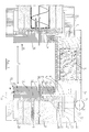
- Figure 1 shows in cross section a door system in which a door 1 is pivotally held in a door frame 2.
- the door frame 2 is shown in section, the section being placed just above a catch 3 belonging to a door lock. Let us first consider the door frame construction recognizable from the right half of the figure.
- the door frame 2 has a metal rail 4, which consists of an approximately T-shaped steel profile, in which the T-beam 5 can be divided into a wall half 5a and a reveal half 5b.
- the foot 6 of the T is connected in one piece to the T-beam 5, an asymmetrical configuration with a longer reveal half 5b and a shorter wall half 5a being provided.
- the aspect ratio of wall half 5a to reveal half 5b is approximately 1: 2.
- the metal rail 4 is connected to masonry 8, namely via a plurality of dowelled screws 9, which are embedded in perforations 10.
- the wall struts 7 have, as can be seen from the drawing Shape, the upper, flat bend 7 'is connected to the metal rail 4 by gluing, screwing or welding.
- the wall struts 7 have a width of approximately 15 cm and are folded from sheet metal.
- the cladding 15 covers at least part of the outside of the metal rail 4 facing away from the masonry 8.
- the cladding consists of a soffit lining 16 and two wall claddings 17 and 18 which are laterally assigned to the soffit lining 16 and are perpendicular to it essentially no supporting function.
- the masonry 8 is plastered (plaster 30), possibly after the attachment of the wall struts 7 and the other parts of the door frame, the parts lying between plaster, masonry and the rear of the cladding are foamed by a plastic foam 19 or stuffed with mineral wool.
- the wall struts 7 are also later embedded in this foam 19.
- the soffit lining 16 is therefore separated from the masonry 8 by a foam layer.
- B. polyurethane glue is glued.
- a further groove 21 is milled into the side region of the soffit lining 16, into which a rubber sealing lip 22 is inserted, against which the door 1 strikes.
- the wall covering 18 is connected to the reveal lining 16 via a conventional spring 23.
- a completely different type of connection is selected.
- the reveal lining 16 does not completely cover the reveal surface of the door opening.
- the metal rail 4 continues in the space which is open between the reveal lining 16 and the wall covering 17, and is visible with the outside of the T-beam 5.
- the wall half 5a forms a boundary of the wall covering 17 on the door leaf side; in the area of the given contact surface 24 there is an adhesive bond or possibly another type of connection between the parts 5 and 17.
- the metal rail 4 thus connects the reveal lining 16 to the wall covering 17.
- the T-foot 6 also has an insertion and threaded sleeve 26 for the foot of a door hinge 27, the T-foot 6 having a through-hole 28 at a compatible point here.
- other connecting elements such as e.g. Clamping elements can be selected. So that the door 1 is connected to the T-foot of the metal rail 4 so that it can easily accommodate the weight and torque of the door 1 hanging in the hinge 27.
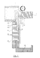
- Figure 2 shows a similar structure to the right half of Figure 1.
- the metal rail here designated by the reference number 40, is formed from two parts, namely a flat plate 41 and an angled rail 42 connected to the flat plate 41, whereby there is essentially a similar T configuration as in FIG. 1.
- Both the flat plate 41 and the angle rail 42 consist of high-strength steel profile, which are connected by gluing, screwing or welding to the profile configuration shown in FIG.
- a groove extension 43 is provided in the immediate vicinity of the part of the flat tab 41 projecting into the groove 20, into which a rubber profile 44 is pressed.
- the rubber profile 43 serves as a seal against the door 1.
- the structure is similar to that according to FIG. 1, so that a further explanation can be dispensed with.
- the door frame is preferably manufactured as a finished rectangular frame, the assembly essentially following the assembly instructions shown in EP-B 0 125 445.
Landscapes
- Engineering & Computer Science (AREA)
- Civil Engineering (AREA)
- Structural Engineering (AREA)
- Door And Window Frames Mounted To Openings (AREA)
- Wing Frames And Configurations (AREA)
- Supports Or Holders For Household Use (AREA)
- Special Wing (AREA)
- Securing Of Glass Panes Or The Like (AREA)
- Fencing (AREA)
- Hinges (AREA)
Claims (9)
- Encadrement de porte se composant d'un rail métalique à relier à la maçonnerie et d'un revêtement en bois ou en une matière non métallique semblable au bois dans lequel le revêtement recouvre au moins une partie du côté extérieur du rail métallique opposé à la maçonnerie et présente en outre un parement d'intrados et un revêtement de paroi, le rail métallique étant, en coupe transversal, un profilé extrudé à configuration de base en forme de L dans lequel la première branche du L est une branche, qui porte le parement d'intrados et qui est reliée à la maçonnerie,
et l'autre branche du L est une branche de paroi qui porte un revêtement de paroi,
caractérisé en ce que la configuration de base en forme du L du rail métallique (4; 40) s'élargit de façon linéaire en une section transversale à profil en T dans laquelle- la première moitié (moitié de paroi 5a) de la barre du T (5) est reliée au revêtement de paroi (17) et limite celui-ci du côté du vantail de porte,- et l'autre moitié (moitié d'intrados 5b) de la barre du T (5) est reliée au parement d'intrados (16) et porte en outre sur le côté intérieur au moins un étai de paroi perforé (7) dans lequel sont insérables des moyens de fixation habituels, comme des vis (9). - Encadrement de porte selon la revendication 1, caractérisé en ce que le rail métallique (4) est éventuellement réalisé d'un seul tenant par soudage de deux fers plats et est de préférence en acier.
- Encadrement de porte selon la revendication 1, caractérisé en ce que le rail métallique (40) se compose d'un couvre-joint plat (41), qui représente sensiblement la barre du T, et d'une cornière (42) relié au couvre-joint plat (40), qui forme le pied du T.
- Encadrement de porte selon l'une des revendications 1 à 3, caractérisé en ce que le rapport entre les longueurs de la moitié de paroi (5a) et de la moitié d'intrados (5b) est environ de 1:2.
- Encadrement de porte selon l'une des revendications 1 à 4, caractérisé en ce que le pied du T (6) et la branche d'intrados (5b) du rail métallique sont sensiblement de la même longueur.
- Encadrement de porte selon l'une des revendications précédentes, caractérisé en ce que la moitié (5b), reliée au parement d'intrados (16), de la barre du T (5), fait saillie dans l'encoche (20) du parement d'intrados (16).
- Encadrement de porte selon la revendication 6, caractérisé en ce qu'il est prévu dans le parement d'intrados (16), dans la zone d'entrée de la moitié (5b) de la barre du T (5), un élargissement formant encoche (43) dans lequel est comprimé un profilé en caoutchouc (44).
- Encadrement de porte selon l'une des revendications précédentes en ce que la liaison de la paumelle (27) avec le pied du T (6) est réalisée, par exemple, au moyen d'une douille à enficher ou d'une douille filetée (26), qui présente un alésage (28) à un emplacement compatible avec la douille (26), ou au moyen d'éléments de serrage.
- Encadrement de porte selon la revendication 1, caractérisé en ce que les étais de paroi (7) présentent une forme enet sont fixés sur le rail métallique (4) par leur extrémité supérieure (7′) dans la zone de l'angle entre le pied et la barre du T.

Priority Applications (1)
| Application Number | Priority Date | Filing Date | Title |
|---|---|---|---|
| AT90123266T ATE85836T1 (de) | 1989-12-19 | 1990-12-05 | Tuerrahmen aus metallschiene und verkleidung. |
Applications Claiming Priority (2)
| Application Number | Priority Date | Filing Date | Title |
|---|---|---|---|
| DE8914908U | 1989-12-19 | ||
| DE8914908U DE8914908U1 (fr) | 1989-12-19 | 1989-12-19 |
Publications (2)
| Publication Number | Publication Date |
|---|---|
| EP0433760A1 EP0433760A1 (fr) | 1991-06-26 |
| EP0433760B1 true EP0433760B1 (fr) | 1993-02-17 |
Family
ID=6845615
Family Applications (1)
| Application Number | Title | Priority Date | Filing Date |
|---|---|---|---|
| EP90123266A Expired - Lifetime EP0433760B1 (fr) | 1989-12-19 | 1990-12-05 | Cadre de porte en métal et revêtement |
Country Status (3)
| Country | Link |
|---|---|
| EP (1) | EP0433760B1 (fr) |
| AT (1) | ATE85836T1 (fr) |
| DE (2) | DE8914908U1 (fr) |
Families Citing this family (3)
| Publication number | Priority date | Publication date | Assignee | Title |
|---|---|---|---|---|
| DE4319945A1 (de) * | 1993-06-16 | 1994-12-22 | Hans Dieter Niemann | Tür- oder Fensterrahmen aus Holz |
| DE29713541U1 (de) * | 1997-07-30 | 1997-09-25 | Diener Horst | Zarge mit Wandmontageprofil |
| CN111891158A (zh) * | 2020-07-29 | 2020-11-06 | 中车长春轨道客车股份有限公司 | 一种轨道车辆高强度车头铝结构 |
Family Cites Families (11)
| Publication number | Priority date | Publication date | Assignee | Title |
|---|---|---|---|---|
| BE432131A (fr) * | ||||
| LU50522A1 (fr) * | 1965-02-24 | 1966-04-24 | ||
| DE1953845A1 (de) * | 1969-10-25 | 1971-05-06 | Josef Kress | Tuer |
| AT323973B (de) * | 1970-04-13 | 1975-08-11 | Kecneerger Herbert | Stockrahmen für türen oder fenster |
| DE2924587A1 (de) * | 1979-06-19 | 1981-01-08 | Kurt Korte | Vorrichtung zum umkleiden einer im mauerwerk fest eingebauten tuerzarge oder sonstiger futter |
| US4443984A (en) * | 1981-06-25 | 1984-04-24 | Rasmussen Robert R | Door, window, and partition casing arrangement for dry wall partitions |
| DE8311697U1 (de) * | 1983-04-20 | 1984-01-26 | Herholz Bernhard Herbers GmbH & Co KG, 4422 Ahaus | Tuerrahmen aus einer holzverkleideten metallzarge |
| NL8400456A (nl) * | 1984-02-13 | 1985-09-02 | Vonder Meubel | Kozijn-vervangend systeem voor deuren, ramen, luiken en dergelijke. |
| DE3444255A1 (de) * | 1984-12-05 | 1986-06-05 | Fischer Svedex-Türenwerk GmbH u. Co KG, 8855 Monheim | Metallprofil fuer eine tuerzarge und tuerzarge hergestellt unter verwendung eines derartigen metallprofils |
| AT385811B (de) * | 1985-05-13 | 1988-05-25 | Blank Herbert | Anordnung zur befestigung einer falz- bzw. einer zierverkleidung an einem in einer wandoeffnung fixierten tuerfutter |
| DE8703872U1 (fr) * | 1987-03-14 | 1987-06-04 | Schneckenburger, Josef, 7209 Deilingen, De |
-
1989
- 1989-12-19 DE DE8914908U patent/DE8914908U1/de not_active Expired - Lifetime
-
1990
- 1990-12-05 DE DE9090123266T patent/DE59000898D1/de not_active Expired - Lifetime
- 1990-12-05 EP EP90123266A patent/EP0433760B1/fr not_active Expired - Lifetime
- 1990-12-05 AT AT90123266T patent/ATE85836T1/de not_active IP Right Cessation
Also Published As
| Publication number | Publication date |
|---|---|
| ATE85836T1 (de) | 1993-03-15 |
| EP0433760A1 (fr) | 1991-06-26 |
| DE8914908U1 (fr) | 1990-02-01 |
| DE59000898D1 (de) | 1993-03-25 |
Similar Documents
| Publication | Publication Date | Title |
|---|---|---|
| DE3433919C2 (de) | Bauwerk, insbesondere Häuschen, Garage oder Unterkunft, mittels vorgefertigter Elemente | |
| DE8501840U1 (de) | Befestigungswinkel für eine Fassadenunterkonstruktion | |
| CH653873A5 (de) | Duschtrennwand. | |
| EP0690951A1 (fr) | Profile mixte bois-aluminium | |
| DE69824833T2 (de) | Befestigungseinheit für die Befestigung von Verkleidungsplatten auf einer Gebäude Fassade- und/oder Bodenplatte befestigten Stütz-mitteln | |
| EP0433760B1 (fr) | Cadre de porte en métal et revêtement | |
| EP0918127B1 (fr) | Châssis de porte et dispositif de montage | |
| CH672655A5 (fr) | ||
| DE3310467C2 (de) | Holzverkleidung für eine Türzarge | |
| DE2502101A1 (de) | Rohrrahmenkonstruktion fuer tueren und festverglasungen, insbesondere in rauchdichter ausfuehrung | |
| EP0078905A2 (fr) | Huisserie d'habillage pour le revêtement d'une ouverture dans une paroi pour une porte ou similaire | |
| DE3301940A1 (de) | Fenster oder tuer mit beplankungsleisten aus holz oder kunststoff | |
| DE19854925C5 (de) | Fenster- oder Türrahmen in Vorsatzrahmen- oder Verbundprofilkonstruktion | |
| DE19719113A1 (de) | Türsystem | |
| DE2934940C2 (de) | Außenfenster zum Verdecken einer Öffnung in einer mit einer Außenverkleidung versehenen Gebäudewand | |
| EP0125445B1 (fr) | Chambranle de porte constitué d'une huisserie métallique revêtue de bois | |
| DE3202833A1 (de) | Verkleidung fuer eine in einem bauwerk befestigte zarge fuer eine zimmer- oder haustuere oder dgl. | |
| DE3543608C1 (en) | Covering for a window or door reveal | |
| EP0902154B1 (fr) | Vitrage pare-feu | |
| EP0201056A2 (fr) | Huisserie | |
| EP0738805B1 (fr) | Elément de raccordement pour cadre de fenêtre | |
| DE2623781B2 (de) | Verkleidungsprofil für alte Blendrahmen | |
| DE4015742C2 (de) | Schließteil-Befestigung an Fenster- oder Türrahmen | |
| DE3941784C2 (fr) | ||
| DE19929664A1 (de) | Rahmenholm einer Glasrahmenkonstruktion für Brandschutzverglasungen |
Legal Events
| Date | Code | Title | Description |
|---|---|---|---|
| PUAI | Public reference made under article 153(3) epc to a published international application that has entered the european phase |
Free format text: ORIGINAL CODE: 0009012 |
|
| AK | Designated contracting states |
Kind code of ref document: A1 Designated state(s): AT BE CH DE FR IT LI LU NL |
|
| 17P | Request for examination filed |
Effective date: 19911223 |
|
| 17Q | First examination report despatched |
Effective date: 19920619 |
|
| GRAA | (expected) grant |
Free format text: ORIGINAL CODE: 0009210 |
|
| AK | Designated contracting states |
Kind code of ref document: B1 Designated state(s): AT BE CH DE FR IT LI LU NL |
|
| REF | Corresponds to: |
Ref document number: 85836 Country of ref document: AT Date of ref document: 19930315 Kind code of ref document: T |
|
| ITF | It: translation for a ep patent filed |
Owner name: NOVELTY SERVICE ING. DI IORIO G. |
|
| REF | Corresponds to: |
Ref document number: 59000898 Country of ref document: DE Date of ref document: 19930325 |
|
| ET | Fr: translation filed | ||
| RAP2 | Party data changed (patent owner data changed or rights of a patent transferred) |
Owner name: HERHOLZ VERTRIEB GMBH & CO. KG |
|
| NLT2 | Nl: modifications (of names), taken from the european patent patent bulletin |
Owner name: HERHOLZ VERTRIEB GMBH & CO. KG TE AHAUS, BONDSREPU |
|
| PLBE | No opposition filed within time limit |
Free format text: ORIGINAL CODE: 0009261 |
|
| STAA | Information on the status of an ep patent application or granted ep patent |
Free format text: STATUS: NO OPPOSITION FILED WITHIN TIME LIMIT |
|
| EPTA | Lu: last paid annual fee | ||
| 26N | No opposition filed | ||
| PGFP | Annual fee paid to national office [announced via postgrant information from national office to epo] |
Ref country code: NL Payment date: 19981123 Year of fee payment: 9 |
|
| PGFP | Annual fee paid to national office [announced via postgrant information from national office to epo] |
Ref country code: BE Payment date: 19981209 Year of fee payment: 9 |
|
| PG25 | Lapsed in a contracting state [announced via postgrant information from national office to epo] |
Ref country code: BE Free format text: LAPSE BECAUSE OF NON-PAYMENT OF DUE FEES Effective date: 19991231 |
|
| BERE | Be: lapsed |
Owner name: HERHOLZ BERNHARD HERBERS G.M.B.H. & CO. K.G. Effective date: 19991231 |
|
| PG25 | Lapsed in a contracting state [announced via postgrant information from national office to epo] |
Ref country code: NL Free format text: LAPSE BECAUSE OF NON-PAYMENT OF DUE FEES Effective date: 20000701 |
|
| NLV4 | Nl: lapsed or anulled due to non-payment of the annual fee |
Effective date: 20000701 |
|
| PG25 | Lapsed in a contracting state [announced via postgrant information from national office to epo] |
Ref country code: IT Free format text: LAPSE BECAUSE OF NON-PAYMENT OF DUE FEES;WARNING: LAPSES OF ITALIAN PATENTS WITH EFFECTIVE DATE BEFORE 2007 MAY HAVE OCCURRED AT ANY TIME BEFORE 2007. THE CORRECT EFFECTIVE DATE MAY BE DIFFERENT FROM THE ONE RECORDED. Effective date: 20051205 |
|
| PGFP | Annual fee paid to national office [announced via postgrant information from national office to epo] |
Ref country code: AT Payment date: 20091217 Year of fee payment: 20 Ref country code: CH Payment date: 20091224 Year of fee payment: 20 Ref country code: LU Payment date: 20091222 Year of fee payment: 20 |
|
| PGFP | Annual fee paid to national office [announced via postgrant information from national office to epo] |
Ref country code: FR Payment date: 20100108 Year of fee payment: 20 |
|
| PGFP | Annual fee paid to national office [announced via postgrant information from national office to epo] |
Ref country code: DE Payment date: 20091222 Year of fee payment: 20 |
|
| REG | Reference to a national code |
Ref country code: CH Ref legal event code: PL |
|
| PG25 | Lapsed in a contracting state [announced via postgrant information from national office to epo] |
Ref country code: DE Free format text: LAPSE BECAUSE OF EXPIRATION OF PROTECTION Effective date: 20101205 |