EP0432402A1 - Dispositif d'injection pour moteur à combustion interne à auto-allumage - Google Patents
Dispositif d'injection pour moteur à combustion interne à auto-allumage Download PDFInfo
- Publication number
- EP0432402A1 EP0432402A1 EP90119503A EP90119503A EP0432402A1 EP 0432402 A1 EP0432402 A1 EP 0432402A1 EP 90119503 A EP90119503 A EP 90119503A EP 90119503 A EP90119503 A EP 90119503A EP 0432402 A1 EP0432402 A1 EP 0432402A1
- Authority
- EP
- European Patent Office
- Prior art keywords
- injection
- pressure
- nozzle
- line
- fuel
- Prior art date
- Legal status (The legal status is an assumption and is not a legal conclusion. Google has not performed a legal analysis and makes no representation as to the accuracy of the status listed.)
- Granted
Links
Images

Classifications
-
- F—MECHANICAL ENGINEERING; LIGHTING; HEATING; WEAPONS; BLASTING
- F02—COMBUSTION ENGINES; HOT-GAS OR COMBUSTION-PRODUCT ENGINE PLANTS
- F02M—SUPPLYING COMBUSTION ENGINES IN GENERAL WITH COMBUSTIBLE MIXTURES OR CONSTITUENTS THEREOF
- F02M45/00—Fuel-injection apparatus characterised by having a cyclic delivery of specific time/pressure or time/quantity relationship
- F02M45/02—Fuel-injection apparatus characterised by having a cyclic delivery of specific time/pressure or time/quantity relationship with each cyclic delivery being separated into two or more parts
- F02M45/04—Fuel-injection apparatus characterised by having a cyclic delivery of specific time/pressure or time/quantity relationship with each cyclic delivery being separated into two or more parts with a small initial part, e.g. initial part for partial load and initial and main part for full load
- F02M45/08—Injectors peculiar thereto
-
- F—MECHANICAL ENGINEERING; LIGHTING; HEATING; WEAPONS; BLASTING
- F02—COMBUSTION ENGINES; HOT-GAS OR COMBUSTION-PRODUCT ENGINE PLANTS
- F02M—SUPPLYING COMBUSTION ENGINES IN GENERAL WITH COMBUSTIBLE MIXTURES OR CONSTITUENTS THEREOF
- F02M55/00—Fuel-injection apparatus characterised by their fuel conduits or their venting means; Arrangements of conduits between fuel tank and pump F02M37/00
- F02M55/02—Conduits between injection pumps and injectors, e.g. conduits between pump and common-rail or conduits between common-rail and injectors
-
- F—MECHANICAL ENGINEERING; LIGHTING; HEATING; WEAPONS; BLASTING
- F02—COMBUSTION ENGINES; HOT-GAS OR COMBUSTION-PRODUCT ENGINE PLANTS
- F02M—SUPPLYING COMBUSTION ENGINES IN GENERAL WITH COMBUSTIBLE MIXTURES OR CONSTITUENTS THEREOF
- F02M59/00—Pumps specially adapted for fuel-injection and not provided for in groups F02M39/00 -F02M57/00, e.g. rotary cylinder-block type of pumps
- F02M59/20—Varying fuel delivery in quantity or timing
- F02M59/36—Varying fuel delivery in quantity or timing by variably-timed valves controlling fuel passages to pumping elements or overflow passages
- F02M59/366—Valves being actuated electrically
-
- F—MECHANICAL ENGINEERING; LIGHTING; HEATING; WEAPONS; BLASTING
- F02—COMBUSTION ENGINES; HOT-GAS OR COMBUSTION-PRODUCT ENGINE PLANTS
- F02M—SUPPLYING COMBUSTION ENGINES IN GENERAL WITH COMBUSTIBLE MIXTURES OR CONSTITUENTS THEREOF
- F02M61/00—Fuel-injectors not provided for in groups F02M39/00 - F02M57/00 or F02M67/00
- F02M61/16—Details not provided for in, or of interest apart from, the apparatus of groups F02M61/02 - F02M61/14
- F02M61/20—Closing valves mechanically, e.g. arrangements of springs or weights or permanent magnets; Damping of valve lift
- F02M61/205—Means specially adapted for varying the spring tension or assisting the spring force to close the injection-valve, e.g. with damping of valve lift
-
- F—MECHANICAL ENGINEERING; LIGHTING; HEATING; WEAPONS; BLASTING
- F02—COMBUSTION ENGINES; HOT-GAS OR COMBUSTION-PRODUCT ENGINE PLANTS
- F02B—INTERNAL-COMBUSTION PISTON ENGINES; COMBUSTION ENGINES IN GENERAL
- F02B3/00—Engines characterised by air compression and subsequent fuel addition
- F02B3/06—Engines characterised by air compression and subsequent fuel addition with compression ignition
Definitions
- the invention relates to an injection device according to the preamble of claim 1.
- a first injection line leads directly to a metering valve unit with cylinder and piston, while a second injection line branches off directly in front of the metering valve unit and opens via a check valve into a line coming from the metering valve unit and leading to the injection valve. Due to the longer first injection line, the piston of the metering valve unit is displaced at the start of delivery and a metered amount of fuel is pre-injected in accordance with the cylinder volume. Due to the extension of the first injection line by the second injection line, the main injection is delayed by the running time.
- a check valve is installed in the second injection line.
- a disadvantage of such a device is the lack of a flexible, external controllability of the quantity and timing of the pre-injection and main injection and the volume storage capacity of the injection lines, since the fuel can no longer be treated as incompressible at the high pressures.
- the pressure build-up process begins in the injection line.
- the resulting pressure wave leads, according to its running time determined by the speed of sound and the length of the injection line to the nozzle holder, to a lifting of the nozzle needle and thus to the injection process.
- the latter also means the removal of fuel volume from the end of the injection line on the nozzle holder side, which, particularly at low engine speeds in the affected line section, leads to a collapse in pressure up to orders of magnitude which result in the nozzle needle being closed in the meantime.
- buffer volume of fuel, which is available in the vicinity of the nozzle holder, during every operating state of the engine.
- Said buffer volume is to be dimensioned at least as large as the fuel quantity resulting from the sum of the pre-injection volume and bypass volume (occurring between the end of the pre-injection and the start of the main injection).
- Planning a certain fuel oversupply for the pre-injection (by means of a suitable choice of the height and slope of the cam of the injection pump) makes sense at the latest when initiating the end of the pre-injection in a known manner with a second, electromagnetically controlled bypass valve - but this time in the immediate vicinity of the Nozzle holder mounted - should be forced.
- the "recovery time" of the pressure at the injection nozzle - which also determines the start of the main injection - is essentially dependent on the sound propagation time of the upstream pressure (which is not influenced by the volume extraction process of the pre-injection) and can therefore lead to a comparatively long pressure build-up time at the nozzle and thus to an intolerable large delay in the main injection.
- the invention is based on the object of compensating for the negative influences of the compressibility on the temporally defined injection course and also of suppressing the undesired wave-mechanical effects.
- the high stand pressure in the injection lines and the check valves inserted downstream in the injection lines compensate, on the one hand, for the negative influence of the compressibility of the fuel and, on the other hand, for the undesirable hydraulic reaction of wave-mechanical effects on the timing of the injection.
- the injection device is thus able to follow the desired injection course with a significantly reduced delay time.
- An injection nozzle adapted to the injection device according to claim 1, can be found in claim 2.
- the stand pressure in the injection lines 3 and 4 can be selected to be very high without the nozzle needle being driven plastically by an excessive force of the closing spring, which would deform the nozzle needle seat.
- bypass valves with pressure regulator function allow the setting of a constant stand pressure in the injection lines.
- the undesired influence of the volume storage capacity is largely eliminated by the hydraulic stand pressure.
- FIG. 1 An injection device according to the invention is shown schematically in FIG. 1.
- the essential components consist of a conventional in-line injection pump 1 and an injection nozzle 2.
- the in-line injection pump 1 is connected to the injection nozzle 2 by means of first and second injection lines 3 and 4, both injection lines 3, 4 branching off directly from a first distributor piece 5, which is connected to a Pressure port 6 of the in-line injection pump 1 is connected.
- the first injection line 3 is selected to be shorter than the second injection line 4 by a transit time difference ⁇ t of a pressure wave emanating from the in-line injection pump 1
- Injection lines 3, 4 are brought together downstream in a second distributor piece 7, a first check valve 8 being installed in the first injection line 3 and a second check valve 9 being installed in the second injection line 4.
- the check valves 8 and 9 are spring-loaded and block the injection lines 3 and 4 against backflow.
- bypass valves 10 and 11 At the two branching points of the two injection lines connected in parallel there are still two electrically operable bypass valves 10 and 11, the first bypass valve 10 being connected directly to the first distributor piece 5 and the second bypass valve 11 to the second distributor piece 7.
- the bypass valves 10 and 11 are preceded by first and second pressure regulating valves 10a and 10b, which can be maintained in lines 3 and 4 by springs, preloaded by springs.
- the injector 2 is also connected to the second distributor.
- the bypass valves 10 and 11 can be controlled electrically via first and second solenoids 12 and 13.
- First and second switches 14 and 15 are provided for actuating the solenoids 12 and 13 and the bypass valves 10 and 11 cooperating therewith.
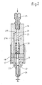
- the injection nozzle 2 differs from the conventional structure of an injection nozzle according to the invention.
- the injection nozzle shown in FIG. 2 also consists of a nozzle holder 16 and a nozzle body 17, which are connected by means of a union nut 18.
- a nozzle needle 19 is axially movable, which is held in the closed position by a closing spring 20.
- the nozzle needle 19 protrudes into a pressure chamber 21 and is provided with a pressure shoulder 22 as a differential piston.
- the pressure shoulder 22 represents a transition to a larger diameter d2.
- the end of the nozzle needle 19 is designed as a piston 23 with a diameter d3.
- a nozzle needle seat 24 at the opposite end has a diameter d1.
- the fuel is supplied via a connection 25 and a first bore 26, which is also the cylinder of the piston 23.
- a second bore 27 branches off from the first bore 26 and opens into the pressure chamber 21.
- Said pressure collapse - preferably occurring at low engine speeds - is due on the one hand to the low displacement speed of the piston from the pump element, but not least also to the above-described effect of the pressure increase as a result of the superposition of two opposing pressure waves.
- This pressure increase effect has an order of magnitude of the volume flow consumption during the pre-injection phase, which - depending on the conditions on the pump element such.
- B. forward stroke and cam shape - can be quite greater than that of the fuel volume flow, as it is fed from the displacement piston of the pump element at the same moment into the first injection line 3.
- first check valve 8 In order to prevent the pressure wave arriving at the end of the second injection line 4 from feeding fuel into the pressure-reduced end of the first injection line 3 facing the nozzle holder 16, the latter is provided there with a first check valve 8. In the same way, penetration of the pressure wave previously entering the first injection line 3 must also be excluded into the second injection line 4, which can also be achieved with a second check valve 9 to be provided on the nozzle holder end.
- Another component of the inventive concept is the combination of the bypass valves 10 and 11 with a pressure control valve 10a and 10b each.
- the push-out phase the pressure control valves 10a and 10b are open
- the fuel pressure can only drop to a standing pressure, which is set to the same size by means of preloaded springs, and which prevails in the injection nozzle even when the displacement piston of the pump element is not in the process of being delivered.
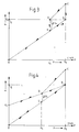
- the force-pressure diagram of a conventional injection nozzle shown there represents the relationship between the force on the nozzle needle shaft (ordinate) and the pressure in the nozzle holder (abscissa).
- the straight line between points 0 and B represents the course of the pressure-related force on the nozzle needle body.
- point B is a force of the amount F2 due to the opening pressure P ⁇ generates the same as the opposite force of a spring that pushes the nozzle needle into its sealing seat.
- the nozzle needle With a slight increase in the line pressure above P ⁇ , the nozzle needle lifts off, which triggers the known increase in the pressure application area on the nozzle needle, which in turn - at the same pressure - leads to a sudden increase in the nozzle needle force (straight line between B and C) in the wider opening Senses, leads to reaching the nozzle needle stop. If the line pressure decreases to the closing pressure P s , the nozzle needle force follows the straight section CD to fall below the amount of the spring force F2 from point D, which means that the nozzle needle falls back into its seat, which at the same time reduces the hydraulic effective area on the Nozzle needle (straight DE).
- the impact energy which occurs as elastic deformation work in the nozzle needle seat, is determined by both the spring force F2 and the rate of decrease in line pressure.
- said deformation work is determined exclusively by the spring force F2 and the distance covered by the nozzle needle.
- a lookout for a closing force-generating system was made characterized by lower impact energies during valve closing.
- the mode of operation of the injection nozzle according to FIG. 2 is as follows:
- the fuel under high pressure enters the pressure chamber 21 via the pressure-resistant connection 25 connected to the nozzle holder 16 via the second and third bores 27 and 27a.
- the fuel pressure acts on the pressure shoulder 22, which results as an annular surface corresponding to the diameter difference, formed from d2 (shaft diameter of the nozzle needle) and d1 (diameter of the sealing seat).
- Another hydraulic contact surface for the line pressure is the, the connection 25 facing the end face of the piston 23 (circular area with diameter d3).
- Both the position and the movement of the nozzle needle 19 are determined by a total of three forces acting directly on the nozzle needle.
Landscapes
- Engineering & Computer Science (AREA)
- Chemical & Material Sciences (AREA)
- Combustion & Propulsion (AREA)
- Mechanical Engineering (AREA)
- General Engineering & Computer Science (AREA)
- Fuel-Injection Apparatus (AREA)
- Electrical Control Of Air Or Fuel Supplied To Internal-Combustion Engine (AREA)
Applications Claiming Priority (2)
| Application Number | Priority Date | Filing Date | Title |
|---|---|---|---|
| DE3937918 | 1989-11-15 | ||
| DE3937918A DE3937918A1 (de) | 1989-11-15 | 1989-11-15 | Einspritzvorrichtung fuer selbstzuendende brennkraftmaschine |
Publications (2)
| Publication Number | Publication Date |
|---|---|
| EP0432402A1 true EP0432402A1 (fr) | 1991-06-19 |
| EP0432402B1 EP0432402B1 (fr) | 1992-12-23 |
Family
ID=6393537
Family Applications (1)
| Application Number | Title | Priority Date | Filing Date |
|---|---|---|---|
| EP90119503A Expired - Lifetime EP0432402B1 (fr) | 1989-11-15 | 1990-10-11 | Dispositif d'injection pour moteur à combustion interne à auto-allumage |
Country Status (6)
| Country | Link |
|---|---|
| US (1) | US5054445A (fr) |
| EP (1) | EP0432402B1 (fr) |
| JP (1) | JPH03222857A (fr) |
| DE (2) | DE3937918A1 (fr) |
| ES (1) | ES2038474T3 (fr) |
| RU (1) | RU2011882C1 (fr) |
Families Citing this family (13)
| Publication number | Priority date | Publication date | Assignee | Title |
|---|---|---|---|---|
| DE4105168A1 (de) * | 1990-12-10 | 1992-06-11 | Man Nutzfahrzeuge Ag | Einspritzsystem fuer luftverdichtende brennkraftmaschinen |
| WO1994027040A1 (fr) * | 1993-05-06 | 1994-11-24 | Cummins Engine Company, Inc. | Distributeur pour systeme de distribution de carburant haute pression |
| US5477827A (en) * | 1994-05-16 | 1995-12-26 | Detroit Diesel Corporation | Method and system for engine control |
| US6026784A (en) | 1998-03-30 | 2000-02-22 | Detroit Diesel Corporation | Method and system for engine control to provide driver reward of increased allowable speed |
| US5445128A (en) * | 1993-08-27 | 1995-08-29 | Detroit Diesel Corporation | Method for engine control |
| US5462030A (en) * | 1994-05-31 | 1995-10-31 | Caterpillar Inc. | Encapsulated adjustable rate shaping device for a fuel injection system |
| US5619969A (en) * | 1995-06-12 | 1997-04-15 | Cummins Engine Company, Inc. | Fuel injection rate shaping control system |
| EP1064457B1 (fr) * | 1998-03-16 | 2002-06-12 | Siemens Aktiengesellschaft | Procede pour determiner le temps d'injection dans un moteur a combustion interne a injection directe |
| US6109536A (en) * | 1998-05-14 | 2000-08-29 | Caterpillar Inc. | Fuel injection system with cyclic intermittent spray from nozzle |
| JP2002004913A (ja) * | 2000-06-26 | 2002-01-09 | Nissan Motor Co Ltd | 圧縮自己着火式内燃機関 |
| DE10123993A1 (de) * | 2001-05-17 | 2002-11-21 | Bosch Gmbh Robert | Kraftstoffeinspritzeinrichtung für eine Brennkraftmaschine |
| RU2659713C1 (ru) * | 2016-07-06 | 2018-07-03 | федеральное государственное бюджетное образовательное учреждение высшего образования "Московский государственный технический университет имени Н.Э. Баумана" (национальный исследовательский университет)" (МГТУ им. Н.Э. Баумана) | Аккумуляторная топливная система дизельного двигателя |
| US11187198B1 (en) * | 2020-09-09 | 2021-11-30 | Caterpillar Inc. | Clamping assembly for a pair of fuel lines and components, systems, and methods thereof |
Citations (4)
| Publication number | Priority date | Publication date | Assignee | Title |
|---|---|---|---|---|
| DE2012485A1 (de) * | 1969-05-07 | 1971-01-14 | Technische Hochschule Otto von Guencke Magdeburg, χ 3010 Magdeburg | Hydraulische Druckstoß Einspntzvor richtung mit Vor und Haupteinspritzung, insbesondere fur Dieselmotoren |
| DE2242344A1 (de) * | 1972-08-29 | 1974-03-14 | Bosch Gmbh Robert | Kraftstoffeinspritzduese fuer brennkraftmaschinen |
| DE3147467C1 (de) * | 1981-12-01 | 1983-04-21 | Daimler-Benz Ag, 7000 Stuttgart | Einspritzanlage fuer Brennkraftmaschinen |
| DE3516537A1 (de) * | 1985-05-08 | 1986-11-13 | M A N Nutzfahrzeuge GmbH, 8000 München | Kraftstoffeinspritzvorrichtung fuer selbstzuendende brennkraftmaschinen |
Family Cites Families (23)
| Publication number | Priority date | Publication date | Assignee | Title |
|---|---|---|---|---|
| DE105945C (fr) * | ||||
| CH96739A (de) * | 1921-01-20 | 1922-11-01 | Schweizerische Lokomotiv | Verfahren und Einrichtung zum Einführen des Brennstoffes in den Verbrennungsraum von Verbrennungsmotoren mit Einspritzung des Brennstoffes allein. |
| FR748088A (fr) * | 1932-01-08 | 1933-06-28 | Fried Krupp Germaniawerft Ag | Procédé d'injection de combustible, en particulier pour moteurs diesel sans compresseur |
| DE724535C (de) * | 1938-04-24 | 1942-08-28 | Kloeckner Humboldt Deutz Ag | Brennstoff-Einspritzvorrichtung |
| CH210264A (de) * | 1939-03-27 | 1940-06-30 | Sulzer Ag | Einspritzeinrichtung an Brennkraftmaschinen. |
| GB538915A (en) * | 1939-05-11 | 1941-08-21 | Sulzer Ag | Improvements in or relating to fuel injection apparatus for internal combustion engines |
| DE713777C (de) * | 1939-11-25 | 1941-11-14 | Henschel & Sohn G M B H | Brennstoffeinspritzvorrichtung fuer Brennkraftmaschinen |
| DE736489C (de) * | 1940-08-16 | 1943-06-18 | Sulzer Ag | Einspritzvorrichtung fuer Brennkraftmaschinen |
| GB562343A (en) * | 1942-04-30 | 1944-06-28 | Raul Pateras Pescara | Improvements relating to fuel-injection systems for internal combustion engines |
| NL292443A (fr) * | 1962-05-09 | |||
| DE1917927A1 (de) * | 1969-04-09 | 1970-10-29 | Bosch Gmbh Robert | Kraftstoffeinspritzpumpe fuer Brennkraftmaschinen |
| DE2240711C3 (de) * | 1972-08-18 | 1981-10-15 | Yanmar Diesel Engine Co., Ltd., Osaka | Kraftstoffeinspritzpumpe für Brennkraftmaschinen |
| GB1599400A (en) * | 1977-06-09 | 1981-09-30 | Lucas Industries Ltd | Fuel injection systems for internal combustion engines |
| DE2834633A1 (de) * | 1978-08-08 | 1980-03-06 | Bosch Gmbh Robert | Vorrichtung zur steuerung der voreinspritzung |
| GB2060052B (en) * | 1979-10-05 | 1983-02-02 | Lucas Industries Ltd | Fuel system for engines |
| FR2481752A1 (fr) * | 1980-04-30 | 1981-11-06 | Renault Vehicules Ind | Amelioration des dispositifs mecaniques d'injection de combustible, notamment pour des moteurs diesel |
| DE3109961A1 (de) * | 1981-03-14 | 1982-08-26 | Daimler-Benz Ag, 7000 Stuttgart | "kraftstoffeinspritzventil fuer brennkraftmaschine" |
| MX154828A (es) * | 1981-12-24 | 1987-12-15 | Lucas Ind Plc | Mejoras en un sistema de inyeccion de combustible para un motor de combustion interna |
| GB2138496A (en) * | 1983-04-15 | 1984-10-24 | Ford Motor Co | Reducing fuel pressure rise at i.c.engine injectors |
| JPS6053661A (ja) * | 1983-09-02 | 1985-03-27 | Hitachi Ltd | デイゼルエンジン用高圧燃料噴射装置 |
| JPS6189975A (ja) * | 1984-10-09 | 1986-05-08 | Diesel Kiki Co Ltd | 内燃機関の燃料噴射ノズル装置 |
| DE3506392A1 (de) * | 1985-02-23 | 1986-09-04 | Motoren-Werke Mannheim AG vorm. Benz Abt. stationärer Motorenbau, 6800 Mannheim | Einspritzsystem fuer einen dieselmotor mit einer hochdruck-einspritzpumpe fuer jeden zylinder |
| JPS63151972U (fr) * | 1987-03-27 | 1988-10-05 |
-
1989
- 1989-11-15 DE DE3937918A patent/DE3937918A1/de not_active Withdrawn
-
1990
- 1990-10-11 EP EP90119503A patent/EP0432402B1/fr not_active Expired - Lifetime
- 1990-10-11 ES ES199090119503T patent/ES2038474T3/es not_active Expired - Lifetime
- 1990-10-11 DE DE9090119503T patent/DE59000661D1/de not_active Expired - Fee Related
- 1990-11-09 US US07/612,262 patent/US5054445A/en not_active Expired - Fee Related
- 1990-11-14 RU SU904831537A patent/RU2011882C1/ru active
- 1990-11-15 JP JP2307321A patent/JPH03222857A/ja active Pending
Patent Citations (4)
| Publication number | Priority date | Publication date | Assignee | Title |
|---|---|---|---|---|
| DE2012485A1 (de) * | 1969-05-07 | 1971-01-14 | Technische Hochschule Otto von Guencke Magdeburg, χ 3010 Magdeburg | Hydraulische Druckstoß Einspntzvor richtung mit Vor und Haupteinspritzung, insbesondere fur Dieselmotoren |
| DE2242344A1 (de) * | 1972-08-29 | 1974-03-14 | Bosch Gmbh Robert | Kraftstoffeinspritzduese fuer brennkraftmaschinen |
| DE3147467C1 (de) * | 1981-12-01 | 1983-04-21 | Daimler-Benz Ag, 7000 Stuttgart | Einspritzanlage fuer Brennkraftmaschinen |
| DE3516537A1 (de) * | 1985-05-08 | 1986-11-13 | M A N Nutzfahrzeuge GmbH, 8000 München | Kraftstoffeinspritzvorrichtung fuer selbstzuendende brennkraftmaschinen |
Non-Patent Citations (3)
| Title |
|---|
| PATENT ABSTRACTS OF JAPAN vol. 11, no. 135 (M-585)(2582) 28 April 1987, & JP-A-61 275569 (HINO) 05 Dezember 1986, * |
| PATENT ABSTRACTS OF JAPAN vol. 4, no. 164 (M-41)(646) 14 November 1980, & JP-A-55 112856 (MITSUBISHI) 01 September 1980, * |
| PATENT ABSTRACTS OF JAPAN vol. 7, no. 71 (M-202)(1216) 24 März 1983, & JP-A-57 212362 (DIESEL KIKI) 27 Dezember 1982, * |
Also Published As
| Publication number | Publication date |
|---|---|
| RU2011882C1 (ru) | 1994-04-30 |
| EP0432402B1 (fr) | 1992-12-23 |
| US5054445A (en) | 1991-10-08 |
| DE59000661D1 (de) | 1993-02-04 |
| ES2038474T3 (es) | 1993-07-16 |
| DE3937918A1 (de) | 1991-05-16 |
| JPH03222857A (ja) | 1991-10-01 |
Similar Documents
| Publication | Publication Date | Title |
|---|---|---|
| EP0141044B1 (fr) | Dispositif d'injection de carburant avec pré-injection et injection principale dans un moteur à combustion interne | |
| EP0591201B1 (fr) | Dispositif d'injection de carburant pour moteurs a combustion interne | |
| DE19640826B4 (de) | Speicherkraftstoffeinspritzvorrichtung und Druckregelvorrichtung hierfür | |
| EP1485609A1 (fr) | Dispositif d'injection de carburant pour des moteurs a combustion interne stationnaires | |
| DE2558789A1 (de) | Hochdruck-kraftstoffeinspritzeinrichtung fuer dieselmotoren | |
| DE2742466A1 (de) | Pumpe-duese fuer luftverdichtende einspritzbrennkraftmaschinen | |
| DE3300876A1 (de) | Kraftstoffeinspritzpumpe | |
| EP0432402B1 (fr) | Dispositif d'injection pour moteur à combustion interne à auto-allumage | |
| DE2126653A1 (de) | Kraftstoffeinspritzeinrichtung für Brennkraftmaschinen | |
| DE3521427C2 (fr) | ||
| DE2126787A1 (de) | Kraftstoffeinspntzeinrichtung fur Brennkraftmaschinen | |
| EP0688950B1 (fr) | Système d'injection de carburant | |
| DE3629751C2 (de) | Voreinspritzvorrichtung für Brennkraftmaschinen | |
| WO2000039450A1 (fr) | Pompe a piston pour carburant sous haute pression | |
| EP0064146B1 (fr) | Système d'injection pour injecter deux combustibles par une seule buse d'injection | |
| DE19647304C1 (de) | Kraftstoffeinspritzanlage für eine Brennkraftmaschine | |
| EP0204982B1 (fr) | Dispositif d'injection de combustible pour moteurs à combustion interne | |
| EP0760425B1 (fr) | Dispositif d'injection | |
| EP0467072B1 (fr) | Injecteur de carburant pour des moteurs à combustion interne à compressiond'air | |
| EP1045975B1 (fr) | Unite servant a commander l'etablissement de la pression dans une unite de pompage | |
| EP0610585B1 (fr) | Dispositif d'injection de combustible à pré-injection et injection principale | |
| EP1377745B1 (fr) | Procede pour actionner une unite pompe-ajutage et unite pompe-ajutage correspondante | |
| DE19916657A1 (de) | Einspritzvorrichtung für Verbrennungsmaschinen, vorzugsweise Dieselmotoren | |
| EP1892409A2 (fr) | Dispositif d'injection de carburant | |
| DE19834763C2 (de) | Pumpe-Leitung-Düse-System |
Legal Events
| Date | Code | Title | Description |
|---|---|---|---|
| PUAI | Public reference made under article 153(3) epc to a published international application that has entered the european phase |
Free format text: ORIGINAL CODE: 0009012 |
|
| AK | Designated contracting states |
Kind code of ref document: A1 Designated state(s): DE ES FR GB IT SE |
|
| 17P | Request for examination filed |
Effective date: 19910709 |
|
| 17Q | First examination report despatched |
Effective date: 19920316 |
|
| ITF | It: translation for a ep patent filed |
Owner name: DE DOMINICIS & MAYER S. |
|
| GRAA | (expected) grant |
Free format text: ORIGINAL CODE: 0009210 |
|
| AK | Designated contracting states |
Kind code of ref document: B1 Designated state(s): DE ES FR GB IT SE |
|
| REF | Corresponds to: |
Ref document number: 59000661 Country of ref document: DE Date of ref document: 19930204 |
|
| ET | Fr: translation filed | ||
| GBT | Gb: translation of ep patent filed (gb section 77(6)(a)/1977) |
Effective date: 19930318 |
|
| REG | Reference to a national code |
Ref country code: ES Ref legal event code: FG2A Ref document number: 2038474 Country of ref document: ES Kind code of ref document: T3 |
|
| PGFP | Annual fee paid to national office [announced via postgrant information from national office to epo] |
Ref country code: SE Payment date: 19930910 Year of fee payment: 4 |
|
| PGFP | Annual fee paid to national office [announced via postgrant information from national office to epo] |
Ref country code: ES Payment date: 19931007 Year of fee payment: 4 |
|
| PLBE | No opposition filed within time limit |
Free format text: ORIGINAL CODE: 0009261 |
|
| STAA | Information on the status of an ep patent application or granted ep patent |
Free format text: STATUS: NO OPPOSITION FILED WITHIN TIME LIMIT |
|
| PGFP | Annual fee paid to national office [announced via postgrant information from national office to epo] |
Ref country code: FR Payment date: 19931029 Year of fee payment: 4 |
|
| 26N | No opposition filed | ||
| PG25 | Lapsed in a contracting state [announced via postgrant information from national office to epo] |
Ref country code: DE Effective date: 19940701 |
|
| PG25 | Lapsed in a contracting state [announced via postgrant information from national office to epo] |
Ref country code: GB Effective date: 19941011 |
|
| PG25 | Lapsed in a contracting state [announced via postgrant information from national office to epo] |
Ref country code: SE Effective date: 19941012 |
|
| PG25 | Lapsed in a contracting state [announced via postgrant information from national office to epo] |
Ref country code: ES Free format text: LAPSE BECAUSE OF EXPIRATION OF PROTECTION Effective date: 19941013 |
|
| EAL | Se: european patent in force in sweden |
Ref document number: 90119503.2 |
|
| GBPC | Gb: european patent ceased through non-payment of renewal fee |
Effective date: 19941011 |
|
| PG25 | Lapsed in a contracting state [announced via postgrant information from national office to epo] |
Ref country code: FR Effective date: 19950630 |
|
| EUG | Se: european patent has lapsed |
Ref document number: 90119503.2 |
|
| REG | Reference to a national code |
Ref country code: FR Ref legal event code: ST |
|
| REG | Reference to a national code |
Ref country code: ES Ref legal event code: FD2A Effective date: 19991007 |
|
| PG25 | Lapsed in a contracting state [announced via postgrant information from national office to epo] |
Ref country code: IT Free format text: LAPSE BECAUSE OF NON-PAYMENT OF DUE FEES;WARNING: LAPSES OF ITALIAN PATENTS WITH EFFECTIVE DATE BEFORE 2007 MAY HAVE OCCURRED AT ANY TIME BEFORE 2007. THE CORRECT EFFECTIVE DATE MAY BE DIFFERENT FROM THE ONE RECORDED. Effective date: 20051011 |