EP0432402A1 - Injection device for self-ignition internal combustion engines - Google Patents
Injection device for self-ignition internal combustion engines Download PDFInfo
- Publication number
- EP0432402A1 EP0432402A1 EP90119503A EP90119503A EP0432402A1 EP 0432402 A1 EP0432402 A1 EP 0432402A1 EP 90119503 A EP90119503 A EP 90119503A EP 90119503 A EP90119503 A EP 90119503A EP 0432402 A1 EP0432402 A1 EP 0432402A1
- Authority
- EP
- European Patent Office
- Prior art keywords
- injection
- pressure
- nozzle
- line
- fuel
- Prior art date
- Legal status (The legal status is an assumption and is not a legal conclusion. Google has not performed a legal analysis and makes no representation as to the accuracy of the status listed.)
- Granted
Links
- 238000002347 injection Methods 0.000 title claims abstract description 157
- 239000007924 injection Substances 0.000 title claims abstract description 157
- 238000002485 combustion reaction Methods 0.000 title claims abstract description 10
- 239000000446 fuel Substances 0.000 claims abstract description 30
- 230000005284 excitation Effects 0.000 claims description 3
- 230000006835 compression Effects 0.000 claims description 2
- 238000007906 compression Methods 0.000 claims description 2
- 238000000034 method Methods 0.000 abstract description 12
- 230000003068 static effect Effects 0.000 abstract description 3
- 230000009467 reduction Effects 0.000 abstract description 2
- 230000008569 process Effects 0.000 description 9
- 238000010586 diagram Methods 0.000 description 6
- 238000006073 displacement reaction Methods 0.000 description 6
- 230000000694 effects Effects 0.000 description 6
- 238000002360 preparation method Methods 0.000 description 4
- 238000007789 sealing Methods 0.000 description 4
- 238000003860 storage Methods 0.000 description 4
- 238000011144 upstream manufacturing Methods 0.000 description 3
- 230000007423 decrease Effects 0.000 description 2
- 230000003111 delayed effect Effects 0.000 description 2
- 230000001419 dependent effect Effects 0.000 description 2
- 230000000977 initiatory effect Effects 0.000 description 2
- 230000004044 response Effects 0.000 description 2
- 230000001133 acceleration Effects 0.000 description 1
- 230000009471 action Effects 0.000 description 1
- 238000000418 atomic force spectrum Methods 0.000 description 1
- 238000000889 atomisation Methods 0.000 description 1
- 230000005540 biological transmission Effects 0.000 description 1
- 230000015556 catabolic process Effects 0.000 description 1
- 230000008859 change Effects 0.000 description 1
- 238000006243 chemical reaction Methods 0.000 description 1
- 230000006735 deficit Effects 0.000 description 1
- 230000018109 developmental process Effects 0.000 description 1
- 238000011038 discontinuous diafiltration by volume reduction Methods 0.000 description 1
- 230000005489 elastic deformation Effects 0.000 description 1
- 238000000605 extraction Methods 0.000 description 1
- 230000002349 favourable effect Effects 0.000 description 1
- 238000004519 manufacturing process Methods 0.000 description 1
- 239000000203 mixture Substances 0.000 description 1
- 230000035515 penetration Effects 0.000 description 1
- 238000011084 recovery Methods 0.000 description 1
- 230000008929 regeneration Effects 0.000 description 1
- 238000011069 regeneration method Methods 0.000 description 1
- 230000001105 regulatory effect Effects 0.000 description 1
- 230000002787 reinforcement Effects 0.000 description 1
- 239000000779 smoke Substances 0.000 description 1
- 238000001228 spectrum Methods 0.000 description 1
- 239000007921 spray Substances 0.000 description 1
- 238000005507 spraying Methods 0.000 description 1
- 230000007704 transition Effects 0.000 description 1
- 230000001960 triggered effect Effects 0.000 description 1
Images

Classifications
-
- F—MECHANICAL ENGINEERING; LIGHTING; HEATING; WEAPONS; BLASTING
- F02—COMBUSTION ENGINES; HOT-GAS OR COMBUSTION-PRODUCT ENGINE PLANTS
- F02M—SUPPLYING COMBUSTION ENGINES IN GENERAL WITH COMBUSTIBLE MIXTURES OR CONSTITUENTS THEREOF
- F02M45/00—Fuel-injection apparatus characterised by having a cyclic delivery of specific time/pressure or time/quantity relationship
- F02M45/02—Fuel-injection apparatus characterised by having a cyclic delivery of specific time/pressure or time/quantity relationship with each cyclic delivery being separated into two or more parts
- F02M45/04—Fuel-injection apparatus characterised by having a cyclic delivery of specific time/pressure or time/quantity relationship with each cyclic delivery being separated into two or more parts with a small initial part, e.g. initial part for partial load and initial and main part for full load
- F02M45/08—Injectors peculiar thereto
-
- F—MECHANICAL ENGINEERING; LIGHTING; HEATING; WEAPONS; BLASTING
- F02—COMBUSTION ENGINES; HOT-GAS OR COMBUSTION-PRODUCT ENGINE PLANTS
- F02M—SUPPLYING COMBUSTION ENGINES IN GENERAL WITH COMBUSTIBLE MIXTURES OR CONSTITUENTS THEREOF
- F02M55/00—Fuel-injection apparatus characterised by their fuel conduits or their venting means; Arrangements of conduits between fuel tank and pump F02M37/00
- F02M55/02—Conduits between injection pumps and injectors, e.g. conduits between pump and common-rail or conduits between common-rail and injectors
-
- F—MECHANICAL ENGINEERING; LIGHTING; HEATING; WEAPONS; BLASTING
- F02—COMBUSTION ENGINES; HOT-GAS OR COMBUSTION-PRODUCT ENGINE PLANTS
- F02M—SUPPLYING COMBUSTION ENGINES IN GENERAL WITH COMBUSTIBLE MIXTURES OR CONSTITUENTS THEREOF
- F02M59/00—Pumps specially adapted for fuel-injection and not provided for in groups F02M39/00 -F02M57/00, e.g. rotary cylinder-block type of pumps
- F02M59/20—Varying fuel delivery in quantity or timing
- F02M59/36—Varying fuel delivery in quantity or timing by variably-timed valves controlling fuel passages to pumping elements or overflow passages
- F02M59/366—Valves being actuated electrically
-
- F—MECHANICAL ENGINEERING; LIGHTING; HEATING; WEAPONS; BLASTING
- F02—COMBUSTION ENGINES; HOT-GAS OR COMBUSTION-PRODUCT ENGINE PLANTS
- F02M—SUPPLYING COMBUSTION ENGINES IN GENERAL WITH COMBUSTIBLE MIXTURES OR CONSTITUENTS THEREOF
- F02M61/00—Fuel-injectors not provided for in groups F02M39/00 - F02M57/00 or F02M67/00
- F02M61/16—Details not provided for in, or of interest apart from, the apparatus of groups F02M61/02 - F02M61/14
- F02M61/20—Closing valves mechanically, e.g. arrangements of springs or weights or permanent magnets; Damping of valve lift
- F02M61/205—Means specially adapted for varying the spring tension or assisting the spring force to close the injection-valve, e.g. with damping of valve lift
-
- F—MECHANICAL ENGINEERING; LIGHTING; HEATING; WEAPONS; BLASTING
- F02—COMBUSTION ENGINES; HOT-GAS OR COMBUSTION-PRODUCT ENGINE PLANTS
- F02B—INTERNAL-COMBUSTION PISTON ENGINES; COMBUSTION ENGINES IN GENERAL
- F02B3/00—Engines characterised by air compression and subsequent fuel addition
- F02B3/06—Engines characterised by air compression and subsequent fuel addition with compression ignition
Definitions
- the invention relates to an injection device according to the preamble of claim 1.
- a first injection line leads directly to a metering valve unit with cylinder and piston, while a second injection line branches off directly in front of the metering valve unit and opens via a check valve into a line coming from the metering valve unit and leading to the injection valve. Due to the longer first injection line, the piston of the metering valve unit is displaced at the start of delivery and a metered amount of fuel is pre-injected in accordance with the cylinder volume. Due to the extension of the first injection line by the second injection line, the main injection is delayed by the running time.
- a check valve is installed in the second injection line.
- a disadvantage of such a device is the lack of a flexible, external controllability of the quantity and timing of the pre-injection and main injection and the volume storage capacity of the injection lines, since the fuel can no longer be treated as incompressible at the high pressures.
- the pressure build-up process begins in the injection line.
- the resulting pressure wave leads, according to its running time determined by the speed of sound and the length of the injection line to the nozzle holder, to a lifting of the nozzle needle and thus to the injection process.
- the latter also means the removal of fuel volume from the end of the injection line on the nozzle holder side, which, particularly at low engine speeds in the affected line section, leads to a collapse in pressure up to orders of magnitude which result in the nozzle needle being closed in the meantime.
- buffer volume of fuel, which is available in the vicinity of the nozzle holder, during every operating state of the engine.
- Said buffer volume is to be dimensioned at least as large as the fuel quantity resulting from the sum of the pre-injection volume and bypass volume (occurring between the end of the pre-injection and the start of the main injection).
- Planning a certain fuel oversupply for the pre-injection (by means of a suitable choice of the height and slope of the cam of the injection pump) makes sense at the latest when initiating the end of the pre-injection in a known manner with a second, electromagnetically controlled bypass valve - but this time in the immediate vicinity of the Nozzle holder mounted - should be forced.
- the "recovery time" of the pressure at the injection nozzle - which also determines the start of the main injection - is essentially dependent on the sound propagation time of the upstream pressure (which is not influenced by the volume extraction process of the pre-injection) and can therefore lead to a comparatively long pressure build-up time at the nozzle and thus to an intolerable large delay in the main injection.
- the invention is based on the object of compensating for the negative influences of the compressibility on the temporally defined injection course and also of suppressing the undesired wave-mechanical effects.
- the high stand pressure in the injection lines and the check valves inserted downstream in the injection lines compensate, on the one hand, for the negative influence of the compressibility of the fuel and, on the other hand, for the undesirable hydraulic reaction of wave-mechanical effects on the timing of the injection.
- the injection device is thus able to follow the desired injection course with a significantly reduced delay time.
- An injection nozzle adapted to the injection device according to claim 1, can be found in claim 2.
- the stand pressure in the injection lines 3 and 4 can be selected to be very high without the nozzle needle being driven plastically by an excessive force of the closing spring, which would deform the nozzle needle seat.
- bypass valves with pressure regulator function allow the setting of a constant stand pressure in the injection lines.
- the undesired influence of the volume storage capacity is largely eliminated by the hydraulic stand pressure.
- FIG. 1 An injection device according to the invention is shown schematically in FIG. 1.
- the essential components consist of a conventional in-line injection pump 1 and an injection nozzle 2.
- the in-line injection pump 1 is connected to the injection nozzle 2 by means of first and second injection lines 3 and 4, both injection lines 3, 4 branching off directly from a first distributor piece 5, which is connected to a Pressure port 6 of the in-line injection pump 1 is connected.
- the first injection line 3 is selected to be shorter than the second injection line 4 by a transit time difference ⁇ t of a pressure wave emanating from the in-line injection pump 1
- Injection lines 3, 4 are brought together downstream in a second distributor piece 7, a first check valve 8 being installed in the first injection line 3 and a second check valve 9 being installed in the second injection line 4.
- the check valves 8 and 9 are spring-loaded and block the injection lines 3 and 4 against backflow.
- bypass valves 10 and 11 At the two branching points of the two injection lines connected in parallel there are still two electrically operable bypass valves 10 and 11, the first bypass valve 10 being connected directly to the first distributor piece 5 and the second bypass valve 11 to the second distributor piece 7.
- the bypass valves 10 and 11 are preceded by first and second pressure regulating valves 10a and 10b, which can be maintained in lines 3 and 4 by springs, preloaded by springs.
- the injector 2 is also connected to the second distributor.
- the bypass valves 10 and 11 can be controlled electrically via first and second solenoids 12 and 13.
- First and second switches 14 and 15 are provided for actuating the solenoids 12 and 13 and the bypass valves 10 and 11 cooperating therewith.
- the injection nozzle 2 differs from the conventional structure of an injection nozzle according to the invention.
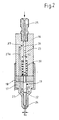
- the injection nozzle shown in FIG. 2 also consists of a nozzle holder 16 and a nozzle body 17, which are connected by means of a union nut 18.
- a nozzle needle 19 is axially movable, which is held in the closed position by a closing spring 20.
- the nozzle needle 19 protrudes into a pressure chamber 21 and is provided with a pressure shoulder 22 as a differential piston.
- the pressure shoulder 22 represents a transition to a larger diameter d2.
- the end of the nozzle needle 19 is designed as a piston 23 with a diameter d3.
- a nozzle needle seat 24 at the opposite end has a diameter d1.
- the fuel is supplied via a connection 25 and a first bore 26, which is also the cylinder of the piston 23.
- a second bore 27 branches off from the first bore 26 and opens into the pressure chamber 21.
- Said pressure collapse - preferably occurring at low engine speeds - is due on the one hand to the low displacement speed of the piston from the pump element, but not least also to the above-described effect of the pressure increase as a result of the superposition of two opposing pressure waves.
- This pressure increase effect has an order of magnitude of the volume flow consumption during the pre-injection phase, which - depending on the conditions on the pump element such.
- B. forward stroke and cam shape - can be quite greater than that of the fuel volume flow, as it is fed from the displacement piston of the pump element at the same moment into the first injection line 3.
- first check valve 8 In order to prevent the pressure wave arriving at the end of the second injection line 4 from feeding fuel into the pressure-reduced end of the first injection line 3 facing the nozzle holder 16, the latter is provided there with a first check valve 8. In the same way, penetration of the pressure wave previously entering the first injection line 3 must also be excluded into the second injection line 4, which can also be achieved with a second check valve 9 to be provided on the nozzle holder end.
- Another component of the inventive concept is the combination of the bypass valves 10 and 11 with a pressure control valve 10a and 10b each.
- the push-out phase the pressure control valves 10a and 10b are open
- the fuel pressure can only drop to a standing pressure, which is set to the same size by means of preloaded springs, and which prevails in the injection nozzle even when the displacement piston of the pump element is not in the process of being delivered.
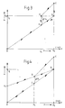
- the force-pressure diagram of a conventional injection nozzle shown there represents the relationship between the force on the nozzle needle shaft (ordinate) and the pressure in the nozzle holder (abscissa).
- the straight line between points 0 and B represents the course of the pressure-related force on the nozzle needle body.
- point B is a force of the amount F2 due to the opening pressure P ⁇ generates the same as the opposite force of a spring that pushes the nozzle needle into its sealing seat.
- the nozzle needle With a slight increase in the line pressure above P ⁇ , the nozzle needle lifts off, which triggers the known increase in the pressure application area on the nozzle needle, which in turn - at the same pressure - leads to a sudden increase in the nozzle needle force (straight line between B and C) in the wider opening Senses, leads to reaching the nozzle needle stop. If the line pressure decreases to the closing pressure P s , the nozzle needle force follows the straight section CD to fall below the amount of the spring force F2 from point D, which means that the nozzle needle falls back into its seat, which at the same time reduces the hydraulic effective area on the Nozzle needle (straight DE).
- the impact energy which occurs as elastic deformation work in the nozzle needle seat, is determined by both the spring force F2 and the rate of decrease in line pressure.
- said deformation work is determined exclusively by the spring force F2 and the distance covered by the nozzle needle.
- a lookout for a closing force-generating system was made characterized by lower impact energies during valve closing.
- the mode of operation of the injection nozzle according to FIG. 2 is as follows:
- the fuel under high pressure enters the pressure chamber 21 via the pressure-resistant connection 25 connected to the nozzle holder 16 via the second and third bores 27 and 27a.
- the fuel pressure acts on the pressure shoulder 22, which results as an annular surface corresponding to the diameter difference, formed from d2 (shaft diameter of the nozzle needle) and d1 (diameter of the sealing seat).
- Another hydraulic contact surface for the line pressure is the, the connection 25 facing the end face of the piston 23 (circular area with diameter d3).
- Both the position and the movement of the nozzle needle 19 are determined by a total of three forces acting directly on the nozzle needle.
Landscapes
- Engineering & Computer Science (AREA)
- Chemical & Material Sciences (AREA)
- Combustion & Propulsion (AREA)
- Mechanical Engineering (AREA)
- General Engineering & Computer Science (AREA)
- Fuel-Injection Apparatus (AREA)
- Electrical Control Of Air Or Fuel Supplied To Internal-Combustion Engine (AREA)
Abstract
Description
Die Erfindung bezieht sich auf eine Einspritzvorrichtung gemäß dem Gattungsbegriff von Anspruch 1.The invention relates to an injection device according to the preamble of claim 1.
Ein wirksames Mittel zur akustischen Entschärfung des Verbrennungsgeräusches an Dieselmotoren ist die Verwirklichung der sogenannten Voreinspritzung. Gelangen in diesem Zusammenhang Einspritzanlagen zum Einsatz deren Kraftstoffversorgung mit konventionellen, von der Nockenwelle des Motors getriebenen Einspritzpumpen - Wirkprinzip Verdrängerkolben - bestritten wird, treten folgende Schwierigkeiten auf. Die jeweils vergleichsweise lange Verbindungsleitung zwischen Pumpenelement und Düse besitzt neben ihrem druckabhängigen Volumenspeichervermögen (in Folge der Volumenkompressibilität des Kraftstoffes) zugleich auch das übliche wellenmechanisch bestimmte Übertragungsverhalten als Antwort auf die schnelle Volumeneinprägung des Kraftstoffes. Reichlich bemessener Hub des Pumpenelementkolbens trägt zwar dem Volumenspeichervermögen der Einspritzleitung Rechnung, vermag jedoch nicht die nachteiligen Folgen des Zeitverzuges der Einspritzvolumen-Verfügbarkeit infolge der endlichen, mit Schallgeschwindigkeit stattfindenden Druckausbereitung in der Leitung auszuschließen.An effective means of acoustically defusing the combustion noise on diesel engines is the implementation of the so-called pre-injection. If, in this connection, injection systems are used whose fuel supply is disputed with conventional injection pumps driven by the camshaft of the engine - the principle of action of the displacement piston - the following difficulties arise. In addition to its pressure-dependent volume storage capacity (as a result of the volume compressibility of the fuel), the comparatively long connecting line between the pump element and nozzle also has the usual wave-mechanically determined transmission behavior in response to the rapid volume injection of the fuel. A sufficient stroke of the pump element piston takes into account the volume storage capacity of the injection line, but cannot exclude the disadvantageous consequences of the delay in availability of the injection volume due to the finite pressure preparation in the line taking place at the speed of sound.
Zur Unterteilung des Einspritzvorganges in eine Vor- und eine Haupteinspritzung ist es nach DE-OS 35 16 537 bekannt, von einer Reiheneinspritzpumpe ausgehend zwei Einspritzleitungen unterschiedlicher Länge vorzusehen. Eine erste Einspritzleitung führt direkt zu einer Dosierventileinheit mit Zylinder und Kolben, während eine zweite Einspritzleitung unmittelbar vor der Dosierventileinheit abzweigt und über ein Rückschlagventil in eine von der Dosierventileinheit kommende und zum Einspritzventil führende Leitung einmündet. Durch die längere erste Einspritzleitung wird bei Förderbeginn der Kolben der Dosierventileinheit verschoben und entsprechend dem Zylindervolumen eine dosierte Brennstoffmenge voreingespritzt. Bedingt durch die Verlängerung der ersten Einspritzleitung um die zweite Einspritzleitung erfolgt die Haupteinspritzung um die Laufzeit zeitlich verzögert. Um Rückwirkungen zu vermeiden ist in die zweite Einspritzleitung ein Rückschlagventil eingebaut. Ein Nachteil einer derartigen Vorrichtung ist das Fehlen einer flexiblen, externen Steuerbarkeit von Menge und zeitlichem Beginn von Vor- und Haupteinspritzung und das Volumenspeichervermögen der Einspritzleitungen, da der Brennstoff bei den hohen Drücken nicht mehr als inkompressibel behandelt werden kann.To subdivide the injection process into a pre-injection and a main injection, it is known according to DE-OS 35 16 537 to provide two injection lines of different lengths starting from an in-line injection pump. A first injection line leads directly to a metering valve unit with cylinder and piston, while a second injection line branches off directly in front of the metering valve unit and opens via a check valve into a line coming from the metering valve unit and leading to the injection valve. Due to the longer first injection line, the piston of the metering valve unit is displaced at the start of delivery and a metered amount of fuel is pre-injected in accordance with the cylinder volume. Due to the extension of the first injection line by the second injection line, the main injection is delayed by the running time. In order to avoid repercussions, a check valve is installed in the second injection line. A disadvantage of such a device is the lack of a flexible, external controllability of the quantity and timing of the pre-injection and main injection and the volume storage capacity of the injection lines, since the fuel can no longer be treated as incompressible at the high pressures.
Einspritzanlagen, bei denen diese Steuerbarkeit, allerdings nur für die Realisierung einer Haupteinspritzung mit Hilfe zweier elektromagnetisch betätigter Bypassventile realisiert wird, sind ferner aus einer Informationsschrift von KHD 1985 bekannt. Mit einem dieser Ventile - in Nähe eines Pumpenelementes installiert - wird mit dem Einleiten der Ventilschließphase der Druckaufbau in der Einspritzleitung gestartet (mit der Folge des Kraftstoffabspritzens in den Brennraum), während ein zweites Ventil - in Düsenhalternähe befindlich - durch Öffnen eines Bypasspfades dazu dient, einen Druckzusammenbruch an der Einspritzdüse mit der Folge des Abbruches des Einspritzvorganges herbeizuführen. Eine elektronische Steuerung sorgt für eine entsprechende Steuerung vom Beginn und Ende der, pro Arbeitsspiel einmaligen Einspritzung. Wird mit dem pumpenelementnahen Bypassventil der zugeordnete Bypasspfad geschlossen, beginnt der Druckaufbauvorgang in der Einspritzleitung. Die im Gefolge entstehende Druckwelle führt, entsprechend ihrer von Schallgeschwindigkeit und Einspritzleitungslänge bestimmten Laufzeit zum Düsenhalter hin, zu einem Abheben der Düsennadel und damit zum Einspritzvorgang. Letzterer bedeutet zugleich Entzug von Kraftstoffvolumen aus dem düsenhalterseitigen Ende der Einspritzleitung, der insbesondere bei niedriger Motordrehzahl im betroffenen Leitungsabschnitt zu einem Zusammenbruch des Druckes bis hin zu Größenordnungen führt, die ein zwischenzeitliches Schließen der Düsennadel zur Folge hat.Injection systems in which this controllability is realized, however, only for the implementation of a main injection with the aid of two electromagnetically actuated bypass valves, are also known from an information document from KHD 1985. With one of these valves - installed near a pump element - the pressure build-up in the injection line is started with the initiation of the valve closing phase (with the result of fuel being sprayed into the combustion chamber), while a second valve - located near the nozzle holder - serves to open a bypass path bring about a pressure collapse at the injection nozzle with the result of the termination of the injection process. An electronic control system ensures appropriate control of the start and end of the injection, which is unique per work cycle. Is the bypass valve close to the pump element assigned bypass path closed, the pressure build-up process begins in the injection line. The resulting pressure wave leads, according to its running time determined by the speed of sound and the length of the injection line to the nozzle holder, to a lifting of the nozzle needle and thus to the injection process. The latter also means the removal of fuel volume from the end of the injection line on the nozzle holder side, which, particularly at low engine speeds in the affected line section, leads to a collapse in pressure up to orders of magnitude which result in the nozzle needle being closed in the meantime.
Als Konsequenz sollte - im Falle einer geplanten Voreinspritzung - dieser Volumenentzug stets durch ein, in Düsenhalternähe bereit stehendes, sofort verfügbares, nachspeisbares "Puffervolumen" von Kraftstoff während jedes Betriebszustandes des Motors kompensiert werden können. Besagtes Puffervolumen ist mindestens so groß zu dimensionieren wie die, sich als Summe aus Voreinspritzvolumen und Beipaßvolumen (zwischen Ende Voreinspritzung und Beginn Haupteinspritzung anfallend) ergebende Kraftstoffmenge. Ein gewisses Kraftstoffüberangebot für die Voreinspritzung zu planen (mittels geeigneter Wahl von Höhe und Steilheit des Nockens der Einspritzpumpe) ist spätestens dann sinnvoll, wenn die Einleitung des Endes der Voreinspritzung in bekannter Weise mit einem zweiten, elektromagnetisch gesteuerten Bypassventil - diesmal jedoch in unmittelbarer Nähe des Düsenhalters montiert - erzwungen werden soll.As a consequence, in the case of a planned pre-injection, this volume reduction should always be compensated for by an immediately available, refillable "buffer volume" of fuel, which is available in the vicinity of the nozzle holder, during every operating state of the engine. Said buffer volume is to be dimensioned at least as large as the fuel quantity resulting from the sum of the pre-injection volume and bypass volume (occurring between the end of the pre-injection and the start of the main injection). Planning a certain fuel oversupply for the pre-injection (by means of a suitable choice of the height and slope of the cam of the injection pump) makes sense at the latest when initiating the end of the pre-injection in a known manner with a second, electromagnetically controlled bypass valve - but this time in the immediate vicinity of the Nozzle holder mounted - should be forced.
Oben genannter Druckzusammenbruch, ob nun durch gesteuerte oder ungesteuerte Voreinspritzung ausgelöst, muß stets dann befürchtet werden, wenn der Entnahmevolumenstrom größer ist als der Speisevolumenstrom, was in Fällen niedriger Verdrängergeschwindigkeit des Kolbens (als Bestandteil des pumpeninternen Einspritzelementes), also bei einem Vorherrschen niedriger Motordrehzahl und geringer Nockenerhebung zutrifft. Von Nachteil ist besagter Druckzusammenbruch spätestens dann, wenn entsprechend den Bedingungen der Praxis ein geringer zeitlicher Abstand zwischen der Voreinspritzung und der Einspritzung der Hauptmenge gefordert wird. Die "Erholzeit" des Druckes an der Einspritzdüse - den zeitlichen Beginn der Haupteinspritzung mitbestimmend - ist im wesentlichen von der Schallaufzeit des stromaufwärts gelegenen (vom Volumenentnahmevorgang der Voreinspritzung nicht beeinflußten) Druckgeschehens abhängig und kann somit durchaus zu einer vergleichsweise langen Druckaufbauzeit an der Düse führen und damit zu einem nicht tolerierbaren großen Zeitverzug der Haupteinspritzung.The above-mentioned pressure collapse, whether triggered by controlled or uncontrolled pilot injection, must always be feared when the withdrawal volume flow is greater than the feed volume flow, which in cases of low displacement speed of the piston (as a component of the pump-internal injection element), i.e. when the engine speed is low and low cam elevation applies. Said pressure collapse is disadvantageous at the latest when, in accordance with the conditions of practice a small time interval between the pre-injection and the injection of the main quantity is required. The "recovery time" of the pressure at the injection nozzle - which also determines the start of the main injection - is essentially dependent on the sound propagation time of the upstream pressure (which is not influenced by the volume extraction process of the pre-injection) and can therefore lead to a comparatively long pressure build-up time at the nozzle and thus to an intolerable large delay in the main injection.
Ausgehend von einer Einspritzvorrichtung gemäß dem Gattungsbegriff liegt der Erfindung die Aufgabe zugrunde, die negativen Einflüsse der Kompressibilität auf den zeitlich definierten Einspritzverlauf zu kompensieren und ferner die unerwünschten wellenmechanischen Rückwirkungen zu unterdrücken.Starting from an injection device according to the generic term, the invention is based on the object of compensating for the negative influences of the compressibility on the temporally defined injection course and also of suppressing the undesired wave-mechanical effects.
Erfindungsgemäß wird diese Aufgabe entsprechend dem kennzeichnenden Teil des Patentanspruches 1 gelöst.According to the invention, this object is achieved in accordance with the characterizing part of patent claim 1.
Durch den hohen Standdruck in den Einspritzleitungen und die in den Einspritzleitungen stromab eingefügten Rückschlagventile wird zum einen der negative Einfluß der Kompressibilität des Brennstoffes und zum anderen die unerwünschte hydraulische Rückwirkung wellenmechanischer Effekte auf den zeitlichen Einspritzverlauf kompensiert. Die Einspritzvorrichtung ist damit in der Lage dem gewünschten Einspritzverlauf mit erheblich verminderter Verzögerungszeit zu folgen.The high stand pressure in the injection lines and the check valves inserted downstream in the injection lines compensate, on the one hand, for the negative influence of the compressibility of the fuel and, on the other hand, for the undesirable hydraulic reaction of wave-mechanical effects on the timing of the injection. The injection device is thus able to follow the desired injection course with a significantly reduced delay time.
Eine Einspritzdüse, angepaßt an die Einspritzvorrichtung gemäß Anspruch 1 ist Anspruch 2 zu entnehmen.An injection nozzle, adapted to the injection device according to claim 1, can be found in
Durch die druckgesteuerte Einspritzdose kann der Standdruck in den Einspritzleitungen 3 und 4 sehr hoch gewählt werden, ohne daß die Düsennadel von einer zu hohen Kraft der Schließfeder getrieben den Düsennadelsitz plastisch verformen würde.By means of the pressure-controlled injection can, the stand pressure in the
Eine vorteilhafte Weiterbildung der Erfindung kann Anspruch 3 entnommen werden. Die mit Druckreglerfunktion versehenen Bypassventile gestatten die Einstellung eines konstanten Standdruckes in den Einspritzleitungen. Durch den hydraulischen Standdruck wird der unerwünschte Einfluß der Volumenspeicherfähigkeit weitgehend eliminiert.An advantageous development of the invention can be found in
Eine weitere vorteilhafte Ausgestaltung der Erfindung kann Anspruch 4 entnommen werden.A further advantageous embodiment of the invention can be found in claim 4.
Ein Ausführungsbeispiel der erfindungsgemäßen Einspritzvorrichtung ist in Zeichnungen dargestellt. Es zeigt:
- Figur 1 eine Reiheneinspritzpumpe mit Einspritzventil
Figur 2 einen Längs schnitt durch ein EinspritzventilFigur 3 ein Druck-Kraft-Diagramm einer konventionellen Einspritzdüse- Figur 4 ein Druck-Kraft-Diagramm einer erfindungsgemäßen Einspritzdüse.
- 1 shows a series injection pump with an injection valve
- Figure 2 shows a longitudinal section through an injection valve
- Figure 3 is a pressure-force diagram of a conventional injector
- Figure 4 is a pressure-force diagram of an injection nozzle according to the invention.
Eine erfindungsgemäße Einspritzvorrichtung ist in Figur 1 schematisch dargestellt. Die wesentlichen Komponenten bestehen aus einer konventionellen Reiheneinspritzpumpe 1 und einer Einspritzdüse 2. Die Reiheneinspritzpumpe 1 wird mittels einer ersten und zweiten Einspritzleitung 3 und 4 mit der Einspritzdüse 2 verbunden, wobei beide Einspritzleitungen 3, 4 unmittelbar von einem ersten Verteilerstück 5 abzweigen, welches mit einem Druckstutzen 6 der Reiheneinspritzpumpe 1 verbunden ist. Die erste Einspritzleitung 3 wird dabei um einen Laufzeitunterschied Δt einer von der Reiheneinspritzpumpe 1 ausgehenden Druckwelle kürzer gewählt als die zweite Einspritzleitung 4. Die Einspritzleitungen 3, 4 werden stromab in einem zweiten Verteilerstück 7 zusammengeführt, wobei in die erste Einspritzleitung 3 ein erstes Rückschlagventil 8 und in die zweite Einspritzleitung 4 ein zweites Rückschlagventil 9 eingebaut ist.An injection device according to the invention is shown schematically in FIG. 1. The essential components consist of a conventional in-line injection pump 1 and an
Die Rückschlagventile 8 und 9 sind federbelastet und sperren die Einspritzleitungen 3 und 4 gegen Rückfluß.The
An den beiden Verzweigungspunkten der beiden, parallel geschalteten Einspritzleitungen befinden sich noch zwei elektrisch betätigbare Bypassventile 10 und 11, wobei das erste Bypassventil 10 unmittelbar an das erste Verteilerstück 5 und das zweite Bypassventil 11 an das zweite Verteilerstück 7 angeschlossen ist. Den Bypassventilen 10 und 11 sind erste und zweite Druckregelventile 10a und 10b vorgeschaltet, die durch Federn vorbelastet in den Leitungen 3 und 4 einen vorgegebenen Druck aufrechterhalten können. Die Einspritzdüse 2 ist ebenfalls an das zweite Verteilerstück angeschlossen.At the two branching points of the two injection lines connected in parallel there are still two electrically
Die Bypassventile 10 und 11 können über erste und zweite Solenoide 12 und 13 auf elektrischem Weg gesteuert werden. Zur Betätigung der Solenoide 12 und 13 und den damit zusammenwirkenden Bypassventilen 10 und 11 sind erste und zweite Schalter 14 und 15 vorgesehen.The
Die Einspritzdüse 2 weicht nach Figur 2 erfindungsgemäß vom konventionellen Aufbau einer Einspritzdüse ab. Übereinstimmend mit den koventionelien Hauptkomponenten von Einspritzdüsen besteht auch die in Figur 2 dargestellte Einspritzdüse aus einem Düsenhalter 16 und einem Düsenkörper 17, die mittels einer Überwurfmutter 18 verbunden sind. Im Düsenkörper 17 ist eine Düsennadel 19 axial beweglich geführt, welche durch eine Schließfeder 20 in Schließstellung gehalten wird. Die Düsennadel 19 ragt in einen Druckraum 21 und ist als Differentialkolben mit einer Druckschulter 22 versehen. Die Druckschulter 22 stellt einen Übergang auf einen größere Durchmesser d2 dar. Am oberen Ende der Düsennadel 19 ist diese als Kolben 23 mit Durchmeser d3 ausgebildet. Ein Düsennadelsitz 24 am gegenüberliegenden Ende weist einen Durchmesser d1 auf. Für die Durchmesserver-hältnisse gilt, daß d3² < d2² - d1² ist. Die Brennstoffzufuhr erfolgt über einen Anschluß 25 und eine erste Bohrung 26, die zugleich der Zylinder des Kolbens 23 ist. Von der ersten Bohrung 26 zweigt eine zweite Bohrung 27 ab, die in den Druckraum 21 einmündet.According to FIG. 2, the
Die Wirkungsweise der erfindungsgemäßen Einspritzvorrichtung wird nachfolgend beschrieben.The mode of operation of the injection device according to the invention is described below.
Beginnt ein Kolben des jeweiligen Pumpenelementes der Reiheneinspritzpumpe 1 Kraftstoff zu fördern, befinden sich die beiden Bypassventile 10 und 11 zunächst in geöffneter Position. Da vom vorausgegangenen Arbeitsspiel her in den beiden Leitungen 3 und 4 noch ein Druck herrscht, wie er von den beiden Druckregelventilen 10a und 10b während der Öffnungsphase der Bypassventile 10 und 11 während der Endphase des Kraftstoff-Förderns erzwungen wird, führt der erneut einsetzende Kraftstoff-Fördervorgang vorerst zu einem Ausschieben im Bereich des ersten Druckregelventils 10a der sich zeitverzögert (gemäß der Schallaufzeit des Druckimpulses) das Öffnen des zweiten Druckregelventils 10b mit der gleichen Auswirkung anschließt. Der so auf Atmosphärendruck entspannte Kraftstoff wird dabei wieder zurück in den Tank geführt.When a piston of the respective pump element of the in-line injection pump 1 begins to deliver fuel, the two
Infolge elektrischen Erregens der Solenoide 12 und 13 mit Hilfe der zugeordneten elektronischen Schalter 14 und 15 wird mit dem davon ausgelösten, nahezu verzögerungsfreien Schließen der Bypassventile 10 und 11 die Druckanhebung in den Leitungen 3 und 4 (über den vorhandenen Standdruck hinaus) zwecks Vorbereitung der Voreinspritzung eingeleitet. Erreicht die Drucksteigerung am Ende der ersten Einspritzleitung 3 einen Wert, der den Öffnungsdruck des Einspritzventils 2 gerade überschreitet, beginnt mit dem Abhebevorgang der Düsennadel 19 (Figur 2) das Einspritzen von Kraftstoff in den Brennraum des Kolbens. Da die Druckanstiegsgeschwindigkeit, aber auch der Betrag der Druckverstärkung im Bereich vor der Einspritzdose wesentlich von der summierenden Wirkung zweier, sich überlagernder Überdruckwellen bestimmt wird - wovon die eine stromabwärts auf den Düsenhalter 16 (Figur 2) zuläuft und die andere, infolge schallharter Reflektion, am bisher geschlossenen Düsennadelsitz stromaufwärts strebt - ist eine Volumenabgabe über den Abspritzvorgang in den Brennraum möglich, die gerade den Kraftstoffbedarf des Voreinspritzvorganges (dessen Ende durch Öffnen des Bypassventils 11 infolge elektrischen Erregens von Solenoid 13 bestimmt wird) decken kann, danach aber zu einem unerwünschten Druckzusammenbruch führt.As a result of electrical excitation of the
Besagter Druckzusammenbruch - vorzugsweise bei niedrigen Motordrehzahlen auftretend - ist zum einen auf die niedrige Verdrängungsgeschwindigkeit des Kolbens vom Pumpenelement zurückzuführen, nicht zuletzt aber auch auf den oben geschilderten Effekt der Druckerhöhung als Folge der Superposition von zwei gegenläufigen Druckwellen. Dieser Druckerhöhungs-Effekt hat eine Größenordnung des Volumenstromverbrauches während der Voreinspritzphase zur Folge, die - abhängig von den Verhältnissen am Pumpenelement wie z. B. Vorhub und Nockenform - durchaus größer sein kann als diejenige des Kraftstoff-Volumenstroms, wie er vom Verdrängerkolben des Pumpenelementes im gleichen Augenblick gerade in die erste Einspritzleitung 3 eingespeist wird. Sinkt nun der Kraftstoffdruck im Düsenhalter infolge Beendigung der Druckwellenüberlagerung (die auf erste Einspritzleitung 3 stromaufwärts zur Einspritzpumpe laufende reflektierte Druckwelle hat das düsenhalterseitige Ende mittlererweise passiert und verlassen) wie aber auch aufgrund der vergleichsweise hohen Volumenentnahme unter das Niveau des Öffnungsdruckes der Einspritzdüse 2, wird damit der Schließvorgang der Zerstäuberdüse eingeleitet.Said pressure collapse - preferably occurring at low engine speeds - is due on the one hand to the low displacement speed of the piston from the pump element, but not least also to the above-described effect of the pressure increase as a result of the superposition of two opposing pressure waves. This pressure increase effect has an order of magnitude of the volume flow consumption during the pre-injection phase, which - depending on the conditions on the pump element such. B. forward stroke and cam shape - can be quite greater than that of the fuel volume flow, as it is fed from the displacement piston of the pump element at the same moment into the
In der Praxis dauert es aufgrund der Leitungslänge der ersten Einspritzleitung 3 zu lange, bis der Druckaufbau an der Düse ein Niveau erreicht, um mittels erneutem Schließen (per Steuerzwang) des Pypassventiles 11 den Beginn der Haupteinspritzung in angemessenem Zeitabstand wieder einleiten zu können. Ein Tatbestand, der letztlich mit der Stromabwärts-Schallaufzeit des von der Volumenentnahme ungestörten Druckgeschehens - im oberen Teil der ersten Einspritzleitung 3 befindlich - zu erklären ist.In practice, due to the length of the
Hier setzt nun der Erfindungsgedanke ein. Er geht von dem Bestreben aus, eine zweite Druckwelle, zeitverzögert um den Betrag des gewünschten Zeitabstandes zwischen Vor- und Haupteinspritzung an der Einspritzdüse zur Verfügung zu stellen, um damit den Volumenbedarf der Haupteinspritzung abdecken zu können. Realisierbar ist dies mit der Installation einer zweiten Einspritzleitung 4, die zur ersten Einspritzleitung 3 parallel zu schalten ist. Der Längenunterschied ist so zu wählen, daß aufgrund der unterschiedlichen Druckwellenlaufzeiten der oben geforderte Zeitverzug zwischen Vor- und Haupteinspritzung erfüllt wird.This is where the idea of the invention begins. It starts from the endeavor to provide a second pressure wave, delayed by the amount of the desired time interval between the pre-injection and the main injection, at the injection nozzle in order to be able to cover the volume requirement of the main injection. This can be achieved by installing a second injection line 4 which is to be connected in parallel with the
Um die zeitversetzt am Ende der zweiten Einspritzleitung 4 einlaufende Druckwelle an einem Einspeisen von Kraftstoff in das druckverarmte, dem Düsenhalter 16 zugewandte Ende von erster Einspritzleitung 3 zu hindern, ist diese dort mit einem ersten Rückschlagventil 8 versehen. In gleicher Weise muß auch ein Eindringen der früher auf ersten Einspritzleitung 3 einlaufenden Druckwelle die zweite Einspritzleitung 4 hinein ausgeschlossen werden, was ebenfalls mit einem, an dessen düsenhalterseitigem Ende vorzusehenen zweiten Rückschlagventil 9 realisierbar ist.In order to prevent the pressure wave arriving at the end of the second injection line 4 from feeding fuel into the pressure-reduced end of the
Ein weiterer Bestandteil des Erfindungsgedankens ist das Kombinieren der Bypassventile 10 und 11 mit jweils einem Druckregelventil 10a und 10b. Während der sogenannten Ausschiebephase (die Druckregelventile 10a und 10b sind geöffnet) kann der Kraftstoffdruck aufgrund dieser Maßnahme nur auf einen - mittels vorgespannter Federn gleichgroß eingestellten - Standdruck absinken, der auch dann in der Einspritzdüse vorherrscht, wenn der Verdrängerkolben des Pumpenelementes nicht im Fördern begriffen ist.Another component of the inventive concept is the combination of the
Die Einführung hohen Standdruckes dient der Absicht, solche Anteile der kraftstoffördernden Verdrängerbewegung des Pumpenelement-Kolbens zur Erzeugung von düsenseitig abgespritzten Kraftstoff zuzuführen, die während der Aufbauphase des Leitungsdruckes bisher ausschließlich zur Aufbringung des dazu notwendigen "Kompressionsvolumens" dienten. Solche "Förderverluste" können während der Druckaufbauphase for die Vorbereitung der Voreinspritzung gerade noch toleriert werden, hingegen bedeuten sie während des extrem schnell zu erfolgenden Druckaufbaues im Zeitraum zwischen absolvierter Voreinspritzung (mit anschließendem Druckzusammenbruch) und beginnender Haupteinspritzung ein nicht hinnehmbares Volumendefizit zu Lasten der benötigten Abspritzmenge. Ein hohes Standdruckniveau bedeutet demnach insbesondere bei niedrigeren Motordrehzahlen eine willkommen schnelle Druckregeneration nach erfolgter Voreinspritzung.The introduction of high static pressure serves the purpose of supplying those portions of the fuel-promoting displacement movement of the pump element piston for the production of fuel sprayed on the nozzle side, which up to now have only served to apply the necessary "compression volume" during the build-up phase of the line pressure. Such "delivery losses" can just be tolerated during the pressure build-up phase for the preparation of the pre-injection, however, they mean an unacceptable volume deficit at the expense of the required spray volume during the extremely rapid build-up of pressure in the period between the pre-injection (followed by a pressure drop) and the beginning of the main injection . A high level of static pressure therefore means a welcome rapid pressure regeneration after pre-injection, especially at lower engine speeds.
Es liegt nahe, den Standdruck der Einspritzleitungen aus vorerwähnten Gründen so hoch wie möglich zu planen. Dem steht allerdings der vergleichsweise niedrige Öffnungsdruck konventioneller Einspritzdüsen entgegen. Diesen Öffnungsdruck viel höher auszulegen stößt auf Schwierigkeiten, die im folgenden anhand eines Diagrammes in Figur 3 verdeutlicht werden sollen. Das dort dargestellte Kraft-Druckdiagramm einer konventionellen Einspritzdüse stellt die Beziehung zwischen Kraft am Düsennadelschaft (Ordinate) und Druck im Düsenhalter (Abszisse) dar. Die wiedergegebene Gerade zwischen den Punkten 0 und B stellt den Verlauf der druckbedingten Kraft am Düsennadelkörper dar. In Punkt B wird infolge des Öffnungsdruckes PÖ eine Kraft vom Betrag F₂ erzeugt die gleich der entgegengesetzt gerichteten Kraft einer Feder ist, die die Düsennadel in ihren Dichtsitz drückt. Bei geringfügiger Steigerung des Leitungsdruckes über PÖ hinaus hebt die Düsennadel ab, was die bekannte Vergrößerung der Druckangriffsfläche an der Düsennadel auslöst, die ihrerseits - bei gleichem Druck - zu einer sprungartigen Vergrößerung der Düsennadel-Kraft (Gerade zwischen B und C) im weiter öffnenden Sinne, bis hin zum Erreichen des Düsennadelanschlages führt. Nimmt der Leitungsdruck bis zum Schließdruck Ps ab, folgt die Düsennadelkraft dem Geraden-Abschnitt C-D um ab dem Punkt D den Betrag der Federkraft F₂ zu unterschreiten, was ein Zurückfallen der Düsennadel in ihren Sitz bedeutet, was gleichzeitig eine Verkleinerung der hydraulischen Wirkfläche an der Düsennadel zur Folge hat (Gerade DE).It makes sense to plan the stand pressure of the injection lines as high as possible for the reasons mentioned above. This is offset by the comparatively low opening pressure of conventional injection nozzles. Designing this opening pressure much higher encounters difficulties, which will be illustrated below with the aid of a diagram in FIG. 3. The force-pressure diagram of a conventional injection nozzle shown there represents the relationship between the force on the nozzle needle shaft (ordinate) and the pressure in the nozzle holder (abscissa). The straight line between
Die Aufprallenergie, die als elastische Formänderungsarbeit im Düsennadelsitz anfällt, wird dabei sowohl von der Federkraft F₂ wie von der Abnahmegeschwindigkeit des Leitungsdruckes bestimmt. Erfolgt der Zusammenbruch des Leitungsdruckes jedoch in einer kürzeren Zeit als derjenigen, die von der Düsennadel zur Zurücklegung des Wegabschnittes zwischen öffnungsbegrenzenden Anschlag und Dichtsitz benötigt wird, was gelegentlich zutrifft, ist besagte Formänderungsarbeit ausschließlich von der Federkraft F₂ und dem zurückgelegten Weg der Düsennadel bestimmt. Da für moderne Einspritzsysteme, die bereits eine hohe Aufsetzgeschwindigkeit der Düsennadel besitzen, Bedenken hinsichtlich einer weiteren Steigerung der Schließkraft F₂ der Feder wegen der Gefahr eines Überschreitens der zulässigen Flächenpressung im Dichtsitz des Einspritzventils anzumelden sind, wurde Ausschau nach einem schließkraftbildenden System gehalten, das sich durch geringere Aufschlagenergien während des Ventilschließens auszeichnet.The impact energy, which occurs as elastic deformation work in the nozzle needle seat, is determined by both the spring force F₂ and the rate of decrease in line pressure. However, if the line pressure collapses in a shorter time than that which is required by the nozzle needle to cover the path section between the opening-limiting stop and the sealing seat, which is sometimes the case, said deformation work is determined exclusively by the spring force F₂ and the distance covered by the nozzle needle. As for modern injection systems, which already have a high placement speed of the nozzle needle, concerns about a further increase in the closing force F₂ of the spring due to the risk of exceeding the permissible surface pressure in the sealing seat of the injection valve have to be registered, so a lookout for a closing force-generating system was made characterized by lower impact energies during valve closing.
Die Wirkungsweise der Einspritzdüse nach Figur 2 ist folgende: Der unter hohen Druck stehende Kraftstoff tritt Ober den mit dem Düsenhalter 16 verbundenen druckfesten Anschluß 25 über die zweiten und dritten Bohrungen 27 und 27a in den Druckraum 21 ein. Dort greift der Kraftstoffdruck an der Druckschulter 22 an, die sich als Kreisringfläche entsprechend der Durchmesserdifferenz, gebildet aus d₂ (Schaftdurchmesser Düsennadel) und d₁ (Durchmesser Dichtsitz) ergibt. Eine weitere hydraulische Angriffsfläche für den Leitungsdruck stellt die, dem Anschluß 25 zugewandte Stirnfläche des Kolbens 23 (Kreisfläche mit Durchmesser d₃) dar.The mode of operation of the injection nozzle according to FIG. 2 is as follows: The fuel under high pressure enters the
Sowohl die Lage, wie die Bewegung der Düsennadel 19 werden von insgesamt drei unmittelbar an der Düsennadel angreifenden Kräften bestimmt. Zum einen handelt es sich um das im Schließsinne wirkende Kräftepaar, herrührend von der Schließfeder 20 und dem Kolben 23 während die entgegengesetzt - also im Öffnungssinne wirkende - dritte Kraftkomponente an der Druckschulter 22 der Düsennadel 19 (im Druckraum 21 befindlich) angreift.Both the position and the movement of the
Die Konsequenzen dieser Vorgehensweise seien anhand des Druck-Kraft-Diagrammes (Figur 4) verdeutlicht. Mit zunehmenden Leitungsdruck folgt die, im Öffnungssinne an einem Schaft der Düsennadel 19 angreifende, sich entsprechend dem Produkt aus Leitungsdruck und hydraulischer Angriffsfläche (Kreisringquerschnitt entsprechend der Durchmesserdifferenz (d₂ - d₁) ergebende Kraft einer Geraden zwischen den Punkten 0 und B. Im gleichen Zeitabschnitt wächst die von der Summe aus Federkraft F₁ der Schließfeder 20 plus hydraulische Zusatzkraft (Produkt aus Leitungsdruck und Kreisquerschnitt d₃ (Kolben 23, Figur 2) repräsentierte Schließkraft auf einen Wert an, die im Punkt B betragsgleich mit der Düsennadel-Öffnungskraft ist. B ist folglich der Schnittpunkt zwischen den Geraden der Schließ- und Öffnungskraft und bestimmt mit dem Vorzeichenwechsel der an der Düsennadel angreifenden Summenkraft den Öffnungsdruck und damit die Größe der "Abhebekraft" der Düsennadel, der ein Öffnungsdruck gemäß der Beziehung
Übersteigt der Leitungsdruck den Öffnungsdruck PÖ, findet eine abrupte Vergrößerung der Öffnungskraft infolge Wirkflächenvergrößerung der Düsennadel auf einen Wert entsprechend dem Durchmesser d₂ statt. Ein Beschleunigen der Düsennadel (Öffnen) bis zum Anschlagen der Düsennadelschulter am Zwischenstück Zw ist die Folge (Geradenabschnitt B - C). Nach erfolgte: Abspritzen des Kraftstoffes in den Brennraum und dem im Gefolge sich einstellenden Abfall des Leitungsdruckes sinkt die Öffnungskraft an der Düsennadel nach einem Bildungsgesetz entsprechend dem Geraden-Abschnitt zwischen den Punkten C und D. Der Punkt D bedeutet wiederum einen Schnittpunkt zwischen Schließ- und Öffnungskraftverlauf und bestimmt damit diesmal den sogenannten Schließdruck:
Geringfügiges Unterschreiten des Schließdruckes löst den Schließvorgang der Düsennadel aus, nach deren Aufsetzen ein schlagartiger Teilzusammenbruch der Öffnungskraft gemäß dem Geraden-Abschnitt D-E infolge Verkleinerung der hydraulischen Angriffsfläche von
Das Diagramm läßt deutlich erkennen, daß bei gleichgroß gefordertem Öffnungsdruck ein System, bei dem die schließkraft der Feder von einer hydraulischen Hilfskraft (erzeugt unter zur Hilfenahme des Leitungsdruckes) Unterstützung erfährt, eine nahezu beliebig schwache Dimensionierung der Schließfeder durch Wahl einer geeigneten Konstellation aller beteiligter hydraulischer Wirkflächen zuläßt. Ganz im Gegensatz also zu einem System, dessen Schließkraft ausschließlich von der Dimensionierung der Schließkraft der Feder bestimmt ist (Figur 3).The diagram clearly shows that if the opening pressure is of the same size, a system in which the closing force of the spring is assisted by a hydraulic assistant (generated using the line pressure) an almost arbitrarily weak dimensioning of the closing spring by choosing a suitable constellation of all hydraulic active surfaces involved. This is in complete contrast to a system whose closing force is determined exclusively by the dimensioning of the closing force of the spring (FIG. 3).
Es läßt sich folglich auch der Umkehrschluß ziehen, nämlich daß bei Forderung nach einem höheren Öffnungsdruck - wie etwa bei der Einführung eines vergleichsweise hohen, an anderer Stelle geforderten Standdruckes - die Einführung einer leitungsdruckgesteuerten Komponente der Schließkraft keineswegs eine zwangsläufige Verstärkung der Schließfeder zur Folge haben muß. An dieser Stelle sei vermerkt, daß diese Methode der Ansprechdruckerhöhung zu günstigeren Tröpfchengrößen-Spektren beim Kraftstoff-Zerstäuben führt, was ein nicht unwesentlicher Beitrag zur besseren Gemischaufbereitung zum Zwecke der Schwarzrauchminderung wie der Kaltstartverbesserung ist.It is therefore also possible to draw the opposite conclusion, namely that the demand for a higher opening pressure - such as the introduction of a comparatively high stand pressure, which is required elsewhere - does not inevitably lead to an inevitable reinforcement of the closing spring as a result of the line pressure-controlled component of the closing force . At this point it should be noted that this method of increasing the response pressure leads to more favorable droplet size spectra for fuel atomization, which is a not insignificant contribution to better mixture preparation for the purpose of reducing black smoke and improving cold starts.
Claims (4)
Applications Claiming Priority (2)
| Application Number | Priority Date | Filing Date | Title |
|---|---|---|---|
| DE3937918 | 1989-11-15 | ||
| DE3937918A DE3937918A1 (en) | 1989-11-15 | 1989-11-15 | INJECTION DEVICE FOR SELF-IGNITIONING INTERNAL COMBUSTION ENGINE |
Publications (2)
| Publication Number | Publication Date |
|---|---|
| EP0432402A1 true EP0432402A1 (en) | 1991-06-19 |
| EP0432402B1 EP0432402B1 (en) | 1992-12-23 |
Family
ID=6393537
Family Applications (1)
| Application Number | Title | Priority Date | Filing Date |
|---|---|---|---|
| EP90119503A Expired - Lifetime EP0432402B1 (en) | 1989-11-15 | 1990-10-11 | Injection device for self-ignition internal combustion engines |
Country Status (6)
| Country | Link |
|---|---|
| US (1) | US5054445A (en) |
| EP (1) | EP0432402B1 (en) |
| JP (1) | JPH03222857A (en) |
| DE (2) | DE3937918A1 (en) |
| ES (1) | ES2038474T3 (en) |
| RU (1) | RU2011882C1 (en) |
Families Citing this family (13)
| Publication number | Priority date | Publication date | Assignee | Title |
|---|---|---|---|---|
| DE4105168A1 (en) * | 1990-12-10 | 1992-06-11 | Man Nutzfahrzeuge Ag | INJECTION SYSTEM FOR AIR COMPRESSING ENGINES |
| AU6828294A (en) * | 1993-05-06 | 1994-12-12 | Cummins Engine Company Inc. | Distributor for a high pressure fuel system |
| US5477827A (en) * | 1994-05-16 | 1995-12-26 | Detroit Diesel Corporation | Method and system for engine control |
| US6026784A (en) * | 1998-03-30 | 2000-02-22 | Detroit Diesel Corporation | Method and system for engine control to provide driver reward of increased allowable speed |
| US5445128A (en) * | 1993-08-27 | 1995-08-29 | Detroit Diesel Corporation | Method for engine control |
| US5462030A (en) * | 1994-05-31 | 1995-10-31 | Caterpillar Inc. | Encapsulated adjustable rate shaping device for a fuel injection system |
| US5619969A (en) * | 1995-06-12 | 1997-04-15 | Cummins Engine Company, Inc. | Fuel injection rate shaping control system |
| WO1999047802A1 (en) * | 1998-03-16 | 1999-09-23 | Siemens Aktiengesellschaft | Method for determining the injection time in a direct injection internal combustion engine |
| US6109536A (en) * | 1998-05-14 | 2000-08-29 | Caterpillar Inc. | Fuel injection system with cyclic intermittent spray from nozzle |
| JP2002004913A (en) * | 2000-06-26 | 2002-01-09 | Nissan Motor Co Ltd | Compression self-ignition type internal combustion engine |
| DE10123993A1 (en) * | 2001-05-17 | 2002-11-21 | Bosch Gmbh Robert | Fuel injection device has pressure maintaining valve between working cavity of pump and first control valve |
| RU2659713C1 (en) * | 2016-07-06 | 2018-07-03 | федеральное государственное бюджетное образовательное учреждение высшего образования "Московский государственный технический университет имени Н.Э. Баумана" (национальный исследовательский университет)" (МГТУ им. Н.Э. Баумана) | Diesel engine accumulator fuel system |
| US11187198B1 (en) * | 2020-09-09 | 2021-11-30 | Caterpillar Inc. | Clamping assembly for a pair of fuel lines and components, systems, and methods thereof |
Citations (4)
| Publication number | Priority date | Publication date | Assignee | Title |
|---|---|---|---|---|
| DE2012485A1 (en) * | 1969-05-07 | 1971-01-14 | Technische Hochschule Otto von Guencke Magdeburg, χ 3010 Magdeburg | Hydraulic surge injection device with pre and main injection, especially for diesel engines |
| DE2242344A1 (en) * | 1972-08-29 | 1974-03-14 | Bosch Gmbh Robert | FUEL INJECTION NOZZLE FOR COMBUSTION MACHINES |
| DE3147467C1 (en) * | 1981-12-01 | 1983-04-21 | Daimler-Benz Ag, 7000 Stuttgart | Injection system for internal combustion engines |
| DE3516537A1 (en) * | 1985-05-08 | 1986-11-13 | M A N Nutzfahrzeuge GmbH, 8000 München | FUEL INJECTION DEVICE FOR SELF-IGNITIONING INTERNAL COMBUSTION ENGINES |
Family Cites Families (23)
| Publication number | Priority date | Publication date | Assignee | Title |
|---|---|---|---|---|
| DE105945C (en) * | ||||
| CH96739A (en) * | 1921-01-20 | 1922-11-01 | Schweizerische Lokomotiv | Method and device for introducing the fuel into the combustion chamber of internal combustion engines with injection of the fuel alone. |
| FR748088A (en) * | 1932-01-08 | 1933-06-28 | Fried Krupp Germaniawerft Ag | Fuel injection process, in particular for diesel engines without compressor |
| DE724535C (en) * | 1938-04-24 | 1942-08-28 | Kloeckner Humboldt Deutz Ag | Fuel injector |
| CH210264A (en) * | 1939-03-27 | 1940-06-30 | Sulzer Ag | Injection device on internal combustion engines. |
| GB538915A (en) * | 1939-05-11 | 1941-08-21 | Sulzer Ag | Improvements in or relating to fuel injection apparatus for internal combustion engines |
| DE713777C (en) * | 1939-11-25 | 1941-11-14 | Henschel & Sohn G M B H | Fuel injection device for internal combustion engines |
| DE736489C (en) * | 1940-08-16 | 1943-06-18 | Sulzer Ag | Injection device for internal combustion engines |
| GB562343A (en) * | 1942-04-30 | 1944-06-28 | Raul Pateras Pescara | Improvements relating to fuel-injection systems for internal combustion engines |
| NL292443A (en) * | 1962-05-09 | |||
| DE1917927A1 (en) * | 1969-04-09 | 1970-10-29 | Bosch Gmbh Robert | Fuel injection pump for internal combustion engines |
| DE2240711C3 (en) * | 1972-08-18 | 1981-10-15 | Yanmar Diesel Engine Co., Ltd., Osaka | Fuel injection pump for internal combustion engines |
| GB1599400A (en) * | 1977-06-09 | 1981-09-30 | Lucas Industries Ltd | Fuel injection systems for internal combustion engines |
| DE2834633C2 (en) * | 1978-08-08 | 1987-05-14 | Robert Bosch Gmbh, 7000 Stuttgart | Device for controlling fuel pre-injection by intermediate relief in a fuel injection system for an internal combustion engine |
| GB2060052B (en) * | 1979-10-05 | 1983-02-02 | Lucas Industries Ltd | Fuel system for engines |
| FR2481752A1 (en) * | 1980-04-30 | 1981-11-06 | Renault Vehicules Ind | IMPROVEMENT OF MECHANICAL FUEL INJECTION DEVICES, IN PARTICULAR FOR DIESEL ENGINES |
| DE3109961A1 (en) * | 1981-03-14 | 1982-08-26 | Daimler-Benz Ag, 7000 Stuttgart | "FUEL INJECTION VALVE FOR INTERNAL COMBUSTION ENGINE" |
| MX154828A (en) * | 1981-12-24 | 1987-12-15 | Lucas Ind Plc | IMPROVEMENTS IN A FUEL INJECTION SYSTEM FOR AN INTERNAL COMBUSTION ENGINE |
| GB2138496A (en) * | 1983-04-15 | 1984-10-24 | Ford Motor Co | Reducing fuel pressure rise at i.c.engine injectors |
| JPS6053661A (en) * | 1983-09-02 | 1985-03-27 | Hitachi Ltd | High pressure fuel injection device for diesel engine |
| JPS6189975A (en) * | 1984-10-09 | 1986-05-08 | Diesel Kiki Co Ltd | Fuel injection nozzle device for internal-combustion engine |
| DE3506392A1 (en) * | 1985-02-23 | 1986-09-04 | Motoren-Werke Mannheim AG vorm. Benz Abt. stationärer Motorenbau, 6800 Mannheim | INJECTION SYSTEM FOR A DIESEL ENGINE WITH A HIGH PRESSURE INJECTION PUMP FOR EVERY CYLINDER |
| JPS63151972U (en) * | 1987-03-27 | 1988-10-05 |
-
1989
- 1989-11-15 DE DE3937918A patent/DE3937918A1/en not_active Withdrawn
-
1990
- 1990-10-11 ES ES199090119503T patent/ES2038474T3/en not_active Expired - Lifetime
- 1990-10-11 EP EP90119503A patent/EP0432402B1/en not_active Expired - Lifetime
- 1990-10-11 DE DE9090119503T patent/DE59000661D1/en not_active Expired - Fee Related
- 1990-11-09 US US07/612,262 patent/US5054445A/en not_active Expired - Fee Related
- 1990-11-14 RU SU904831537A patent/RU2011882C1/en active
- 1990-11-15 JP JP2307321A patent/JPH03222857A/en active Pending
Patent Citations (4)
| Publication number | Priority date | Publication date | Assignee | Title |
|---|---|---|---|---|
| DE2012485A1 (en) * | 1969-05-07 | 1971-01-14 | Technische Hochschule Otto von Guencke Magdeburg, χ 3010 Magdeburg | Hydraulic surge injection device with pre and main injection, especially for diesel engines |
| DE2242344A1 (en) * | 1972-08-29 | 1974-03-14 | Bosch Gmbh Robert | FUEL INJECTION NOZZLE FOR COMBUSTION MACHINES |
| DE3147467C1 (en) * | 1981-12-01 | 1983-04-21 | Daimler-Benz Ag, 7000 Stuttgart | Injection system for internal combustion engines |
| DE3516537A1 (en) * | 1985-05-08 | 1986-11-13 | M A N Nutzfahrzeuge GmbH, 8000 München | FUEL INJECTION DEVICE FOR SELF-IGNITIONING INTERNAL COMBUSTION ENGINES |
Non-Patent Citations (3)
| Title |
|---|
| PATENT ABSTRACTS OF JAPAN vol. 11, no. 135 (M-585)(2582) 28 April 1987, & JP-A-61 275569 (HINO) 05 Dezember 1986, * |
| PATENT ABSTRACTS OF JAPAN vol. 4, no. 164 (M-41)(646) 14 November 1980, & JP-A-55 112856 (MITSUBISHI) 01 September 1980, * |
| PATENT ABSTRACTS OF JAPAN vol. 7, no. 71 (M-202)(1216) 24 März 1983, & JP-A-57 212362 (DIESEL KIKI) 27 Dezember 1982, * |
Also Published As
| Publication number | Publication date |
|---|---|
| DE3937918A1 (en) | 1991-05-16 |
| RU2011882C1 (en) | 1994-04-30 |
| EP0432402B1 (en) | 1992-12-23 |
| DE59000661D1 (en) | 1993-02-04 |
| ES2038474T3 (en) | 1993-07-16 |
| JPH03222857A (en) | 1991-10-01 |
| US5054445A (en) | 1991-10-08 |
Similar Documents
| Publication | Publication Date | Title |
|---|---|---|
| EP0141044B1 (en) | Fuel injection device with main and pre-injection for internal-combustion engines | |
| EP0591201B1 (en) | Fuel injection device for internal combustion engines | |
| DE69618549T2 (en) | FUEL INJECTION CONTROL SYSTEM | |
| DE69619949T2 (en) | Reservoir fuel injection device | |
| DE19640826B4 (en) | Storage fuel injection device and pressure control device therefor | |
| EP1485609A1 (en) | Device for injecting fuel to stationary internal combustion engines | |
| DE2558789A1 (en) | HIGH PRESSURE FUEL INJECTION DEVICE FOR DIESEL ENGINES | |
| DE2742466A1 (en) | PUMP NOZZLE FOR AIR-COMPRESSING INJECTION COMBUSTION MACHINES | |
| DE3300876A1 (en) | FUEL INJECTION PUMP | |
| EP0432402B1 (en) | Injection device for self-ignition internal combustion engines | |
| DE2126653A1 (en) | Fuel injection device for internal combustion engines | |
| DE3521427C2 (en) | ||
| DE2126787A1 (en) | Fuel injection device for internal combustion engines | |
| EP0688950B1 (en) | Fuel injection system | |
| DE3629751C2 (en) | Pre-injection device for internal combustion engines | |
| WO2000039450A1 (en) | Piston pump for high-pressure fuel generation | |
| EP0064146B1 (en) | Injection system for injecting two fuels through one injection nozzle | |
| DE19647304C1 (en) | Fuel injector for internal combustion engine | |
| EP0204982B1 (en) | Fuel injection for internal-combustion engines | |
| EP0760425A1 (en) | Injection device | |
| EP0467072B1 (en) | Fuel injection device for air compressing-combustion | |
| EP1045975B1 (en) | Control unit for controlling the build-up of pressure in a pump unit | |
| EP0610585B1 (en) | Fuel injection device with pilot- and main-injection | |
| EP1377745B1 (en) | Method for operating a pump-nozzle unit and a corresponding pump-nozzle unit | |
| DE19916657A1 (en) | Injector for internal combustion engines, especially diesel engines, injector has preloaded accumulator piston installed in main piston in pressure medium flow path and is movable against spring force |
Legal Events
| Date | Code | Title | Description |
|---|---|---|---|
| PUAI | Public reference made under article 153(3) epc to a published international application that has entered the european phase |
Free format text: ORIGINAL CODE: 0009012 |
|
| AK | Designated contracting states |
Kind code of ref document: A1 Designated state(s): DE ES FR GB IT SE |
|
| 17P | Request for examination filed |
Effective date: 19910709 |
|
| 17Q | First examination report despatched |
Effective date: 19920316 |
|
| ITF | It: translation for a ep patent filed | ||
| GRAA | (expected) grant |
Free format text: ORIGINAL CODE: 0009210 |
|
| AK | Designated contracting states |
Kind code of ref document: B1 Designated state(s): DE ES FR GB IT SE |
|
| REF | Corresponds to: |
Ref document number: 59000661 Country of ref document: DE Date of ref document: 19930204 |
|
| ET | Fr: translation filed | ||
| GBT | Gb: translation of ep patent filed (gb section 77(6)(a)/1977) |
Effective date: 19930318 |
|
| REG | Reference to a national code |
Ref country code: ES Ref legal event code: FG2A Ref document number: 2038474 Country of ref document: ES Kind code of ref document: T3 |
|
| PGFP | Annual fee paid to national office [announced via postgrant information from national office to epo] |
Ref country code: SE Payment date: 19930910 Year of fee payment: 4 |
|
| PGFP | Annual fee paid to national office [announced via postgrant information from national office to epo] |
Ref country code: ES Payment date: 19931007 Year of fee payment: 4 |
|
| PLBE | No opposition filed within time limit |
Free format text: ORIGINAL CODE: 0009261 |
|
| STAA | Information on the status of an ep patent application or granted ep patent |
Free format text: STATUS: NO OPPOSITION FILED WITHIN TIME LIMIT |
|
| PGFP | Annual fee paid to national office [announced via postgrant information from national office to epo] |
Ref country code: FR Payment date: 19931029 Year of fee payment: 4 |
|
| 26N | No opposition filed | ||
| PG25 | Lapsed in a contracting state [announced via postgrant information from national office to epo] |
Ref country code: DE Effective date: 19940701 |
|
| PG25 | Lapsed in a contracting state [announced via postgrant information from national office to epo] |
Ref country code: GB Effective date: 19941011 |
|
| PG25 | Lapsed in a contracting state [announced via postgrant information from national office to epo] |
Ref country code: SE Effective date: 19941012 |
|
| PG25 | Lapsed in a contracting state [announced via postgrant information from national office to epo] |
Ref country code: ES Free format text: LAPSE BECAUSE OF EXPIRATION OF PROTECTION Effective date: 19941013 |
|
| EAL | Se: european patent in force in sweden |
Ref document number: 90119503.2 |
|
| GBPC | Gb: european patent ceased through non-payment of renewal fee |
Effective date: 19941011 |
|
| PG25 | Lapsed in a contracting state [announced via postgrant information from national office to epo] |
Ref country code: FR Effective date: 19950630 |
|
| EUG | Se: european patent has lapsed |
Ref document number: 90119503.2 |
|
| REG | Reference to a national code |
Ref country code: FR Ref legal event code: ST |
|
| REG | Reference to a national code |
Ref country code: ES Ref legal event code: FD2A Effective date: 19991007 |
|
| PG25 | Lapsed in a contracting state [announced via postgrant information from national office to epo] |
Ref country code: IT Free format text: LAPSE BECAUSE OF NON-PAYMENT OF DUE FEES;WARNING: LAPSES OF ITALIAN PATENTS WITH EFFECTIVE DATE BEFORE 2007 MAY HAVE OCCURRED AT ANY TIME BEFORE 2007. THE CORRECT EFFECTIVE DATE MAY BE DIFFERENT FROM THE ONE RECORDED. Effective date: 20051011 |