EP0428892B1 - Serrure cylindrique double - Google Patents
Serrure cylindrique double Download PDFInfo
- Publication number
- EP0428892B1 EP0428892B1 EP90120389A EP90120389A EP0428892B1 EP 0428892 B1 EP0428892 B1 EP 0428892B1 EP 90120389 A EP90120389 A EP 90120389A EP 90120389 A EP90120389 A EP 90120389A EP 0428892 B1 EP0428892 B1 EP 0428892B1
- Authority
- EP
- European Patent Office
- Prior art keywords
- cylinder
- key
- operating knob
- double lock
- knob
- Prior art date
- Legal status (The legal status is an assumption and is not a legal conclusion. Google has not performed a legal analysis and makes no representation as to the accuracy of the status listed.)
- Expired - Lifetime
Links
Images


Classifications
-
- E—FIXED CONSTRUCTIONS
- E05—LOCKS; KEYS; WINDOW OR DOOR FITTINGS; SAFES
- E05B—LOCKS; ACCESSORIES THEREFOR; HANDCUFFS
- E05B47/00—Operating or controlling locks or other fastening devices by electric or magnetic means
- E05B47/06—Controlling mechanically-operated bolts by electro-magnetically-operated detents
- E05B47/0657—Controlling mechanically-operated bolts by electro-magnetically-operated detents by locking the handle, spindle, follower or the like
- E05B47/0661—Controlling mechanically-operated bolts by electro-magnetically-operated detents by locking the handle, spindle, follower or the like axially, i.e. with an axially engaging blocking element
-
- E—FIXED CONSTRUCTIONS
- E05—LOCKS; KEYS; WINDOW OR DOOR FITTINGS; SAFES
- E05B—LOCKS; ACCESSORIES THEREFOR; HANDCUFFS
- E05B47/00—Operating or controlling locks or other fastening devices by electric or magnetic means
- E05B47/06—Controlling mechanically-operated bolts by electro-magnetically-operated detents
- E05B47/0611—Cylinder locks with electromagnetic control
- E05B47/0615—Cylinder locks with electromagnetic control operated by handles, e.g. by knobs
-
- E—FIXED CONSTRUCTIONS
- E05—LOCKS; KEYS; WINDOW OR DOOR FITTINGS; SAFES
- E05B—LOCKS; ACCESSORIES THEREFOR; HANDCUFFS
- E05B47/00—Operating or controlling locks or other fastening devices by electric or magnetic means
- E05B47/06—Controlling mechanically-operated bolts by electro-magnetically-operated detents
- E05B47/0611—Cylinder locks with electromagnetic control
- E05B47/0619—Cylinder locks with electromagnetic control by blocking the rotor
- E05B47/0623—Cylinder locks with electromagnetic control by blocking the rotor axially, i.e. with an axially engaging blocking element
-
- E—FIXED CONSTRUCTIONS
- E05—LOCKS; KEYS; WINDOW OR DOOR FITTINGS; SAFES
- E05B—LOCKS; ACCESSORIES THEREFOR; HANDCUFFS
- E05B47/00—Operating or controlling locks or other fastening devices by electric or magnetic means
- E05B47/06—Controlling mechanically-operated bolts by electro-magnetically-operated detents
- E05B47/0611—Cylinder locks with electromagnetic control
- E05B47/0638—Cylinder locks with electromagnetic control by disconnecting the rotor
- E05B47/0642—Cylinder locks with electromagnetic control by disconnecting the rotor axially, i.e. with an axially disengaging coupling element
-
- E—FIXED CONSTRUCTIONS
- E05—LOCKS; KEYS; WINDOW OR DOOR FITTINGS; SAFES
- E05B—LOCKS; ACCESSORIES THEREFOR; HANDCUFFS
- E05B47/00—Operating or controlling locks or other fastening devices by electric or magnetic means
- E05B2047/0048—Circuits, feeding, monitoring
- E05B2047/0057—Feeding
- E05B2047/0064—Feeding by solar cells
-
- E—FIXED CONSTRUCTIONS
- E05—LOCKS; KEYS; WINDOW OR DOOR FITTINGS; SAFES
- E05B—LOCKS; ACCESSORIES THEREFOR; HANDCUFFS
- E05B47/00—Operating or controlling locks or other fastening devices by electric or magnetic means
- E05B47/0001—Operating or controlling locks or other fastening devices by electric or magnetic means with electric actuators; Constructional features thereof
- E05B47/0002—Operating or controlling locks or other fastening devices by electric or magnetic means with electric actuators; Constructional features thereof with electromagnets
- E05B47/0006—Operating or controlling locks or other fastening devices by electric or magnetic means with electric actuators; Constructional features thereof with electromagnets having a non-movable core; with permanent magnet
Definitions
- the invention relates to a double locking cylinder with a cylinder core provided on one side with a key channel and the tumblers scanning the key, which are shifted from the appropriate key into the free position and with a locking member hub arranged between the two cylinders and this associated coupling and an electromagnetically operating locking device. / Unlocking device, which can be brought into effect depending on an associated coding of the key.
- a double lock cylinder designed in this way is known from DE-OS 37 12 300, a signal receiver to be acted upon by the appropriate key being arranged on the lock cylinder on its outside face of the lock cylinder web, via which it can be read whether the lock is correctly coded by a key Key should be operated.
- the locking / unlocking device is designed in such a way that a spring-loaded flat slide located laterally next to the tumblers in the lock cylinder web engages in an additional tumbler recess in the cylinder core, whereby the cylinder core is additionally locked against rotation. If a correctly coded key is used, the flat slide is moved back against the spring force by means of an armature lever which is now attracted by an excited electromagnet.
- the power supply of the signal receiver and the electromagnetic locking / unlocking device takes place here by means of a power cable via an external power source, in particular via a battery.
- the locking / unlocking device is arranged as a structural unit in a built-in housing, which in a to the lock recess in Area of the web of the lock cylinder adjacent recess is housed, which results in a weakening of the lock cylinder web cross-section.
- a double locking cylinder designed in this way is not suitable for use in conventional mortise locks. For this purpose, structural changes to the mortise lock or the door are required to ensure a power supply. This in turn has the disadvantage that if the power supply fails, for example due to the battery being discharged, the locking cylinder can no longer be actuated.
- the object of the present invention is to design a generic double locking cylinder in such a way that a reliable function is always guaranteed and that the double locking cylinder is suitable for retrofitting in existing, conventional mortise locks without structural changes.
- a double locking cylinder is created, in which a reliable function is always ensured by the fact that one side of the cylinder has an actuating knob equipped on its surface with solar cells, which has an internal battery powered by the solar cell current.
- the solar cells on the inside of the actuating knob only require a lower amount of light energy in order to convert this into electrical energy and to supply it to the battery.
- the electromagnetic locking / unlocking device is therefore supplied with a current of the same magnitude. A failure of the power supply and a related malfunction of the locking cylinder is therefore excluded.
- the locking cylinder has an internal power supply in this embodiment, an electrical connection to parts located outside the locking cylinder, for example a mortise lock fitted with a battery, is not necessary, which means that this self-sufficient locking cylinder can be used in any commercially available mortise lock, without making structural changes to the mortise lock or the door beforehand.
- the electrically powered assemblies of the electromechanical locking / unlocking device are advantageously accommodated in the interior of the actuating knob. This configuration has the advantage that the cross section of the lock cylinder web is not weakened. Furthermore, the components of the locking / unlocking device are protected against manipulation and damage in the inside of the operating knob.
- the locking / unlocking device is designed in such a way that the rotary movement of the actuation purchase can be blocked by a pin extending from the actuation knob to the cylinder housing face, which can be brought into a corresponding position both by the attraction force of an electromagnet and by an axial outward displacement of the actuation knob.
- This configuration expediently combines the advantage of a cylinder side of a double locking cylinder to be operated from the inside of the door by means of the actuating knob and the advantage of a profile cylinder relating to the other cylinder side with additional coding.
- the double locking cylinder can be actuated from the inside of the door at any time by moving it axially outwards, the one used to lock the Rotary movement of the actuating knob responsible pin emerges from a recess provided on the cylinder housing end face.
- a key actuation of the double locking cylinder on the outside of the door provided that the key is correctly coded in addition, causes the electromagnet arranged in the actuating knob to be tightened and the associated displacement of the pin out of the recess in the end face of the cylinder housing.
- the signals queried by the additional coding of the key are transferred to the actuating knob via a sliding contact connection between the actuating knob and the cylinder housing end face.
- This sliding contact connection consists of a knob-side, axially aligned ring contact and a cylinder housing-side contact pin scanning the ring contact.
- the ring contact is in electrical connection with the electrically powered assemblies of the electromagnetically operating locking / unlocking device and the contact pin with the signal transmitter which interrogates the additional coding of the key. If a correctly coded key is used, the signal generator on the cylinder housing sends a corresponding signal to the knob-side electromagnet via the sliding contact connection. This now moves the locking pin by means of its attractive force from the recess of the cylinder housing end face. As a result, the actuating knob can be freely rotated and the double locking cylinder can thus be actuated from the outside of the door by means of the key.
- the contact pin on the cylinder housing is spring-loaded in the direction of the ring contact of the actuating knob. Inaccuracies regarding the distance between the confirmation knob and the cylinder housing face can thus be compensated for, with the sliding contact connection always remaining optimal.
- a Advantageous further development is that a battery storage compartment of the actuating knob can be exposed by opening the front plate of the actuating knob. It is therefore possible to easily replace a defective battery from the inside of the door.
- the mechanical connection between the double locking cylinder and the actuating knob taking into account the possibility of extending the actuating knob axially outward, is achieved in that the actuating knob sits on an axially inwardly sprung shaft which extends to the coupling of the closing member hub and in which lies on the inwardly End is supported in the direction of the key channel of the other cylinder side, a coupling piece on which the key tip engages.
- Rotation of the cylinder core arranged in the profile cylinder part of the double locking cylinder thus goes hand in hand with a simultaneous rotation of the actuating knob.
- the double locking cylinder When the double locking cylinder is actuated from the inside of the door, the actuating knob is displaced axially outward against the spring force, the shaft of the actuating knob still being in engagement with the coupling piece of the locking member hub. In this axially displaced position of the actuating knob, the double locking cylinder can be actuated by rotating the same.
- the outer surface of the actuating knob forms a polygon and the individual surfaces are each equipped with a solar cell.
- the outer surface of the actuating knob is designed as a dodecagon is. This configuration offers the user an advantageous handling of the actuating knob, but the individual surfaces of the lateral surface are designed in such a way that they can be equipped with commercially available solar cell elements.
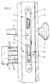
- a mortise lock 3 provided with the usual equipment is seated in its lock pocket 2.
- the latch 4 of the mortise lock 3 is actuated in the usual way by a lever 6 assigned to the inside of the door 5.
- An outer button 8 is molded onto the outer fitting 7 of the door 1.
- the door bolt 9 is moved via a double locking cylinder 10, which can be operated on the outside of the door using a key 11 and on the inside of the door using an actuating knob 12.
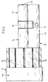
- the double locking cylinder 10 has an asymmetrical structure and is designed such that a profile cylinder section 13 is assigned to the outside of the door and a knob cylinder section 14 is assigned to the inside of the door. Between these cylinder sections 13 and 14, a lock bit recess 15 is provided in the usual way.
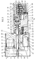
- a cylindrical driver core 17 is arranged in the end region facing the lock bit recess 15, which partially projects from the core bore 16 into the lock bit recess 15 and here a locking member hub 18 carries, the driver core 17 extends approximately to the middle of the locking member hub 18.
- An axial blind bore 19 extends from the end face of the portion of the driving core 17 which carries the locking member hub 18, for receiving a coupling piece 20 which is designed in the usual way.
- this coupling piece 20 there is a spiral spring 21 in the blind bore 19, which the coupling piece 20 strives for To extend direction to the profile cylinder section 13.
- the locking member hub 18 and the driving core 17 are connected via a driving pin 23 which penetrates both parts and is mounted in an axial longitudinal slot 22 of the coupling piece 20.
- a web 24 is formed on the driver core 17. This is in engagement with an axially mounted shaft 25, which is essentially smaller in diameter than the inner diameter of the core bore 16. Only in its end assigned to the driver core 17 does the shaft 25 have a shaft section 26 corresponding to the inner diameter of the core bore 16. The engagement of the web 24 takes place in a receiving slot 27 which starts from the end face of the shaft section 26 and whose length is somewhat greater than the length of the web 24.
- the bearing of the outside of the knob cylinder section 14 for receiving the actuating knob 12 shaft 25 is carried out on the one hand via the shaft section 26 and on the other hand via a screwed into the outer end region of the core bore 16 in a thread having an axial bore 28 corresponding to the diameter of the shaft 25 and having a bearing body 29.
- a compression spring 30 supported on the inside of the bearing body 29 acts on the shaft section 26 supported on the driver core 17.
- the actuating knob 12 has a twelve-sided cross section, with the actuating knob 12 being assigned solar cells 32 for each individual surface 31 'of the outer surface 31.
- One of the axial bore 33 serves to receive the shaft 25, the mechanical connection of which to the actuating knob 12 is realized by means of a clamping screw 34 assigned to the actuating knob 12 and acting radially on the shaft 25.
- the actuating knob 12 has two recesses on its side facing away from the locking cylinder. One recess serves as a receiving compartment 35 for receiving a rechargeable battery 36. The other recess serves for receiving an electromagnet 37 and a pivoting lever 38 assigned to it.
- a locking pin 39 which in the basic position has a locking pin between the recess for receiving the electromagnet 37 and the cutout 40 formed on the side of the actuating knob 12 facing the locking cylinder and penetrates into a locking groove 42 made in the web 41 of the knob cylinder section 14.
- the locking pin 39 is held in its basic position by a compression spring 43 which acts on the other end of the pivoting lever 38.
- the actuating knob 12 On its side opposite the locking cylinder, the actuating knob 12 has a closure cap 44, which is composed of a cylinder section 45 that projects a few millimeters beyond the outer surface 31 equipped with the solar cells 32 and a circular cover plate 46 arranged thereon.
- the cover plate 46 bears in the center on its inside a cylindrical projection 49 which is provided with a bore 47 for receiving a fastening screw 48 and which, in the assembled state, is supported on the end face of the shaft 25 connected to the actuating knob 12, the fastening screw 48 in an axial threaded bore 50 of the shaft 25 is turned.
- a cylinder core 51 is rotatably supported in the profile cylinder section 13 of the double locking cylinder 10. Otherwise, the profile cylinder section 13 has the usual pin tumblers 52, which lie in a common central plane of the housing, in which a key channel 53 also runs in the cylinder core 51.
- This extension serves to receive an insulating jacket 55, in the receiving chamber 56 of which a spring-loaded contact 57 is slidably mounted.
- the insulating jacket 55 On the end face facing the tumbler bore 54, the insulating jacket 55 has a passage opening 58 which is smaller in diameter than the receiving chamber 56.
- a contact pin 60 is formed on the underside of the housing pin 59 of the corresponding pin tumbler 52. This is enclosed by a spiral spring 61, which is supported on the one hand on the end face of the insulating jacket 55 and on the other hand on the underside of the housing pin 59 and strives to shift the pin tumbler 52 into a position blocking the cylinder core 51.
- the contact 57 is connected to a contact pin 63 via an electrical line 62 embedded in the locking cylinder web.
- This is mounted in an insulating housing 64, which lies in a blind bore 66 extending from the cylinder housing end face 65 facing the actuating knob 12.
- the contact pin 63 is spring-loaded in the direction of the actuating knob 12 and penetrates the end face of the insulating housing 64.
- the tip of the contact 63 is supported here on an axially aligned ring contact 67 which is embedded in the end face of the actuating knob 12 and insulated against it 68 designated sliding contact connection now represents an electrical connection between the contact 57 of the profile cylinder section 13 and the assemblies in the actuating knob 12.
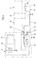
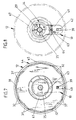
- FIG. 4 serves to illustrate the electrical processes in the double locking cylinder 10.
- the solar cells 32 feed the battery 36 which is connected in parallel to the latter, the positive pole of which is connected to the positive contact of the electromagnet 37 via a line.
- the minus contact of the electromagnet 37 is connected via the sliding contact connection 68 to a contact of the signal transmitter arranged in the profile cylinder section 13, which is shown in the diagram as a simple on / off switch 69 for clarification.
- the other contact is connected to the negative pole of the battery 36 via a ground line.
- the ground line is realized in the exemplary embodiment described in that the line of the negative pole of the rechargeable battery 36 is connected to the shaft 25 and, via this, to the non-insulated housing pin 59 mounted in the locking cylinder.
- closing the switch 69 closes the circuit, which has the consequence that the electromagnet 37 picks up and thus moves the locking pin 39 arranged on the pivoting lever 38 out of the locking groove 42.
- the double locking cylinder can be actuated from the inside of the door at any time by displacing the actuating knob 12 axially outwards against the spring force of the spring 30 and as a result of which the locking pin 39 leaves the locking groove 42.
- the actuating knob 12 can now be freely rotated and the double locking cylinder 12 can thus be actuated (see FIG. 6).
Landscapes
- Physics & Mathematics (AREA)
- Electromagnetism (AREA)
- Lock And Its Accessories (AREA)
- Vehicle Body Suspensions (AREA)
- Infusion, Injection, And Reservoir Apparatuses (AREA)
- Chairs Characterized By Structure (AREA)
- Fluid-Damping Devices (AREA)
Claims (10)
- Cylindre de serrure double (10) muni d'un noyau de cylindre (51) prévu d'un côté du cylindre, d'un passage de clé (53) et de paillettes (52) de sondage de la clé (11), qui sont déplacées par la clé correspondante (11) en position de libération, et d'un moyeu d'organe de serrure (18) disposé entre les deux cylindres (13, 14) et du couplage associé à ces éléments ainsi que d'un dispositif de verrouillage/déverrouillage à actionnement électrique et qui est susceptible d'être mis en action en fonction d'un codage correspondant de la clé (11) et de permettre la rotation de la clé, caractérisé en ce que l'autre côté (14) du cylindre porte un bouton d'actionnement (12) équipé à sa surface de cellules solaires (32) et qui comporte à l'intérieur un accumulateur (36) alimenté par le courant des cellules solaires afin d'assurer l'alimentation en courant du dispositif de verrouillage/déverrouillage.
- Cylindre de serrure double selon la revendication 1, caractérisé en ce que les composants à alimentation électrique (électro-aimant 37) du dispositif de verrouillage/déverrouillage à fonctionnement électromagnétique sont également disposés à l'intérieur du bouton d'actionnement (12).
- Cylindre de serrure double selon l'une ou plusieurs des revendications précédentes, caractérisé en ce que le mouvement de rotation du bouton d'actionnement (12) est susceptible d'être bloqué par une tige (tige de blocage 39) qui relie le bouton d'actionnement (12) à la surface frontale de boîtier de cylindre (65) et qui est susceptible d'être amenée dans une position correspondante aussi bien par la force d'attraction d'un électro-aimant (37) qu'également par un déplacement axial vers l'extérieur du bouton d'actionnement (12).
- Cylindre de serrure double selon l'une ou plusieurs des revendications précédentes, caractérisé par une liaison à contact glissant (68) entre le bouton d'actionnement (12) et la surface frontale de boîtier de cylindre (65) pour l'amenée dans le bouton d'actionnement (12) des signaux demandés par le codage supplémentaire de la clé (11).
- Cylindre de serrure double selon l'une ou plusieurs des revendications précédentes, caractérisé en ce que la liaison à contact glissant (68) est constituée du côté du bouton d'actionnement par un contact annulaire (67) orienté axialement et du côté du boîtier de cylindre, par une tige de contact (63) venant en appui sur le contact annulaire (67).
- Cylindre de serrure double selon l'une ou plusieurs des revendications précédentes, caractérisé en ce que la tige de contact (63) du côté du boîtier du cylindre est sollicitée élastiquement en direction du contact annulaire (67) du bouton d'actionnement (12).
- Cylindre de serrure double selon l'une ou plusieurs des revendications précédentes, caractérisé par un logement de réception d'accumulateur (35) du bouton d'actionnement (12) susceptible d'être libéré par ouverture de la plaque frontale (capuchon de fermeture 44) du bouton d'actionnement (12).
- Cylindre de serrure double selon l'une ou plusieurs des revendications précédentes, caractérisé en ce que le bouton d'actionnement (12) est monté sur un arbre (25) sollicité élastiquement dans la direction axiale vers l'intérieur pour atteindre l'accouplement du moyeu d'organe de serrure (18), dans lequel est logée, à l'extrémité intérieure, une pièce d'accouplement (20) sur laquelle agit la pointe de la clé et qui est sollicitée élastiquement selon la direction du passage de clé (53) de l'autre côté (13) du cylindre.
- Cylindre de serrure double selon l'une ou plusieurs des revendications précédentes, caractérisé en ce que la surface d'enveloppe (31) du bouton d'actionnement (13) forme un polygone et les surfaces individuelles (31') sont équipées chacune d'une cellule solaire (32).
- Cylindre de serrure double selon l'une ou plusieurs des revendications précédentes, caractérisé en ce que la surface d'enveloppe (31) du bouton d'actionnement (12) présente la forme d'un dodécagone.
Priority Applications (1)
| Application Number | Priority Date | Filing Date | Title |
|---|---|---|---|
| AT90120389T ATE84106T1 (de) | 1989-11-23 | 1990-10-24 | Doppel-schliesszylinder. |
Applications Claiming Priority (2)
| Application Number | Priority Date | Filing Date | Title |
|---|---|---|---|
| DE3938791A DE3938791A1 (de) | 1989-11-23 | 1989-11-23 | Doppel-schliesszylinder |
| DE3938791 | 1989-11-23 |
Publications (3)
| Publication Number | Publication Date |
|---|---|
| EP0428892A2 EP0428892A2 (fr) | 1991-05-29 |
| EP0428892A3 EP0428892A3 (en) | 1991-12-18 |
| EP0428892B1 true EP0428892B1 (fr) | 1992-12-30 |
Family
ID=6394034
Family Applications (1)
| Application Number | Title | Priority Date | Filing Date |
|---|---|---|---|
| EP90120389A Expired - Lifetime EP0428892B1 (fr) | 1989-11-23 | 1990-10-24 | Serrure cylindrique double |
Country Status (6)
| Country | Link |
|---|---|
| EP (1) | EP0428892B1 (fr) |
| AT (1) | ATE84106T1 (fr) |
| DE (2) | DE3938791A1 (fr) |
| DK (1) | DK0428892T3 (fr) |
| ES (1) | ES2037514T3 (fr) |
| GR (1) | GR3007503T3 (fr) |
Families Citing this family (11)
| Publication number | Priority date | Publication date | Assignee | Title |
|---|---|---|---|---|
| JP3473044B2 (ja) * | 1993-04-28 | 2003-12-02 | 株式会社デンソー | スパークプラグ |
| EP0805905B1 (fr) * | 1995-01-24 | 2000-04-26 | DORMA GmbH + Co. KG | Mécanisme de fermeture de porte |
| DE19853207C2 (de) * | 1998-11-18 | 2001-02-01 | Simons & Voss Identifikationss | Schließvorrichtung |
| DE19940247A1 (de) * | 1999-08-25 | 2001-03-08 | Winkhaus Fa August | Schließeinrichtung |
| AT409020B (de) * | 1999-11-03 | 2002-05-27 | Roto Frank Eisenwaren | Mehrriegelverschluss |
| DE60110103T2 (de) * | 2000-08-22 | 2006-06-01 | Kowalczyk, Piotr Leonard | Schloss |
| FR2849085A1 (fr) * | 2003-04-16 | 2004-06-25 | Reelax France Sa | Cylindre de serrure perfectionne et serrure correspondante |
| PT1574643E (pt) * | 2004-03-11 | 2012-03-30 | Keso Ag | Cilindro de fecho electromecânico |
| EP1951976A2 (fr) * | 2005-11-24 | 2008-08-06 | Palladio Systeme GmbH | Cylindre de fermeture electromecanique et procede pour commander le deverrouillage d'un cylindre de fermeture electromecanique |
| AT502682B1 (de) * | 2006-08-07 | 2007-05-15 | Evva Werke | Vorrichtung zur zutrittskontrolle |
| AT513051B1 (de) * | 2012-09-06 | 2014-01-15 | Evva Sicherheitstechnologie | Schließeinrichtung mit Verbindungsmittel, welche elektrische Kontakte und Gegenkontakte aufweisen |
Family Cites Families (4)
| Publication number | Priority date | Publication date | Assignee | Title |
|---|---|---|---|---|
| DE3606531A1 (de) * | 1986-02-28 | 1987-09-03 | Fliether Karl Gmbh & Co | Schliesszylinder mit antrieb |
| FR2609090A1 (fr) * | 1986-12-29 | 1988-07-01 | Ferraye Joseph | Systeme de fermeture ou de blocage de toutes sortes de portes qui bloque les barres avec l'encadrement |
| DE3711501A1 (de) * | 1987-04-04 | 1988-10-13 | Heinz Raible | Sicherheitsschloss |
| DE3712300A1 (de) * | 1987-04-10 | 1988-10-27 | Bks Gmbh | Profilschliesszylinder, insbesondere fuer einsteckschloesser |
-
1989
- 1989-11-23 DE DE3938791A patent/DE3938791A1/de active Granted
-
1990
- 1990-10-24 ES ES199090120389T patent/ES2037514T3/es not_active Expired - Lifetime
- 1990-10-24 DK DK90120389.3T patent/DK0428892T3/da active
- 1990-10-24 DE DE9090120389T patent/DE59000694D1/de not_active Expired - Fee Related
- 1990-10-24 EP EP90120389A patent/EP0428892B1/fr not_active Expired - Lifetime
- 1990-10-24 AT AT90120389T patent/ATE84106T1/de not_active IP Right Cessation
-
1993
- 1993-03-30 GR GR930400688T patent/GR3007503T3/el unknown
Also Published As
| Publication number | Publication date |
|---|---|
| EP0428892A3 (en) | 1991-12-18 |
| DE3938791A1 (de) | 1991-06-06 |
| GR3007503T3 (fr) | 1993-08-31 |
| ATE84106T1 (de) | 1993-01-15 |
| EP0428892A2 (fr) | 1991-05-29 |
| ES2037514T3 (es) | 1993-06-16 |
| DK0428892T3 (da) | 1993-05-10 |
| DE59000694D1 (de) | 1993-02-11 |
| DE3938791C2 (fr) | 1991-12-12 |
Similar Documents
| Publication | Publication Date | Title |
|---|---|---|
| EP1574643B1 (fr) | Cylindre de serrure électromécanique | |
| EP1636454B1 (fr) | Barillet electromagnetique | |
| DE112007001299B4 (de) | Nockenschloss mit rückziehbarem Dorn | |
| EP0462316B1 (fr) | Serrure cylindrique double avec verrouillage électrique | |
| EP0428892B1 (fr) | Serrure cylindrique double | |
| EP2239401B1 (fr) | Cylindre de fermeture rotatif électromécanique | |
| EP2110501B1 (fr) | Agencement de cylindre de fermeture | |
| EP0995864B1 (fr) | Système de verrouillage électromécanique | |
| EP0324096A2 (fr) | Serrure à cylindre, notamment cylindre pour serrure encastrée | |
| DE19930054C5 (de) | Elektromechanisches Schließsystem | |
| EP1155427A1 (fr) | Dispositif pour la reception et le maintien d'un dispositif d'identification, tel qu'une cle electronique, en particulier pour un demarreur a allumage | |
| EP0668422A1 (fr) | Mécanisme de blocage pour serrure | |
| DE102004046778B4 (de) | Schließzylinder mit erhöhter Eingriffssicherheit | |
| EP0887495B1 (fr) | Système d'accouplement pour dispositifs de fermeture électroniques | |
| EP0805905B1 (fr) | Mécanisme de fermeture de porte | |
| DE10324690A1 (de) | Ferngesteuert freigebbarer Schließzylinder | |
| DE102005034325A1 (de) | Beschlagsatz | |
| EP0882858B1 (fr) | Serrure cylindrique à goupille électromagnétique | |
| DE4000643B4 (de) | Türschloß, insbesondere Einsteckschloß | |
| EP0709533B1 (fr) | Serrure cylindrique à goupille électromagnétique | |
| AT525744B1 (de) | Schließeinrichtung | |
| AT524794B1 (de) | Zylinderschloss | |
| DE10258151C1 (de) | Schliesszylinder mit elektronisch angesteuerter Kupplung | |
| DE10311986A1 (de) | Schließzylinder | |
| DE10249972A1 (de) | Kupplungsanordnung in einem Schließzylinder oder dergleichen |
Legal Events
| Date | Code | Title | Description |
|---|---|---|---|
| PUAI | Public reference made under article 153(3) epc to a published international application that has entered the european phase |
Free format text: ORIGINAL CODE: 0009012 |
|
| AK | Designated contracting states |
Kind code of ref document: A2 Designated state(s): AT BE CH DE DK ES FR GB GR IT LI LU NL SE |
|
| PUAL | Search report despatched |
Free format text: ORIGINAL CODE: 0009013 |
|
| AK | Designated contracting states |
Kind code of ref document: A3 Designated state(s): AT BE CH DE DK ES FR GB GR IT LI LU NL SE |
|
| 17P | Request for examination filed |
Effective date: 19920116 |
|
| 17Q | First examination report despatched |
Effective date: 19920424 |
|
| GRAA | (expected) grant |
Free format text: ORIGINAL CODE: 0009210 |
|
| AK | Designated contracting states |
Kind code of ref document: B1 Designated state(s): AT BE CH DE DK ES FR GB GR IT LI LU NL SE |
|
| REF | Corresponds to: |
Ref document number: 84106 Country of ref document: AT Date of ref document: 19930115 Kind code of ref document: T |
|
| ET | Fr: translation filed | ||
| REF | Corresponds to: |
Ref document number: 59000694 Country of ref document: DE Date of ref document: 19930211 |
|
| GBT | Gb: translation of ep patent filed (gb section 77(6)(a)/1977) |
Effective date: 19930222 |
|
| ITF | It: translation for a ep patent filed |
Owner name: STUDIO JAUMANN |
|
| REG | Reference to a national code |
Ref country code: DK Ref legal event code: T3 |
|
| REG | Reference to a national code |
Ref country code: ES Ref legal event code: FG2A Ref document number: 2037514 Country of ref document: ES Kind code of ref document: T3 |
|
| REG | Reference to a national code |
Ref country code: GR Ref legal event code: FG4A Free format text: 3007503 |
|
| PLBE | No opposition filed within time limit |
Free format text: ORIGINAL CODE: 0009261 |
|
| STAA | Information on the status of an ep patent application or granted ep patent |
Free format text: STATUS: NO OPPOSITION FILED WITHIN TIME LIMIT |
|
| EPTA | Lu: last paid annual fee | ||
| 26N | No opposition filed | ||
| EAL | Se: european patent in force in sweden |
Ref document number: 90120389.3 |
|
| PGFP | Annual fee paid to national office [announced via postgrant information from national office to epo] |
Ref country code: SE Payment date: 19971015 Year of fee payment: 8 |
|
| PG25 | Lapsed in a contracting state [announced via postgrant information from national office to epo] |
Ref country code: SE Free format text: LAPSE BECAUSE OF NON-PAYMENT OF DUE FEES Effective date: 19981025 |
|
| PGFP | Annual fee paid to national office [announced via postgrant information from national office to epo] |
Ref country code: GR Payment date: 19981030 Year of fee payment: 9 |
|
| EUG | Se: european patent has lapsed |
Ref document number: 90120389.3 |
|
| PG25 | Lapsed in a contracting state [announced via postgrant information from national office to epo] |
Ref country code: GR Free format text: LAPSE BECAUSE OF NON-PAYMENT OF DUE FEES Effective date: 19991031 |
|
| REG | Reference to a national code |
Ref country code: GB Ref legal event code: IF02 |
|
| PGFP | Annual fee paid to national office [announced via postgrant information from national office to epo] |
Ref country code: FR Payment date: 20051005 Year of fee payment: 16 |
|
| PGFP | Annual fee paid to national office [announced via postgrant information from national office to epo] |
Ref country code: CH Payment date: 20051010 Year of fee payment: 16 Ref country code: DE Payment date: 20051010 Year of fee payment: 16 Ref country code: GB Payment date: 20051010 Year of fee payment: 16 Ref country code: LU Payment date: 20051010 Year of fee payment: 16 Ref country code: DK Payment date: 20051010 Year of fee payment: 16 |
|
| PGFP | Annual fee paid to national office [announced via postgrant information from national office to epo] |
Ref country code: BE Payment date: 20051013 Year of fee payment: 16 Ref country code: NL Payment date: 20051013 Year of fee payment: 16 Ref country code: AT Payment date: 20051013 Year of fee payment: 16 |
|
| PGFP | Annual fee paid to national office [announced via postgrant information from national office to epo] |
Ref country code: ES Payment date: 20051014 Year of fee payment: 16 |
|
| PG25 | Lapsed in a contracting state [announced via postgrant information from national office to epo] |
Ref country code: AT Free format text: LAPSE BECAUSE OF NON-PAYMENT OF DUE FEES Effective date: 20061024 |
|
| PG25 | Lapsed in a contracting state [announced via postgrant information from national office to epo] |
Ref country code: LI Free format text: LAPSE BECAUSE OF NON-PAYMENT OF DUE FEES Effective date: 20061031 Ref country code: DK Free format text: LAPSE BECAUSE OF NON-PAYMENT OF DUE FEES Effective date: 20061031 Ref country code: CH Free format text: LAPSE BECAUSE OF NON-PAYMENT OF DUE FEES Effective date: 20061031 |
|
| PGFP | Annual fee paid to national office [announced via postgrant information from national office to epo] |
Ref country code: IT Payment date: 20061031 Year of fee payment: 17 |
|
| PG25 | Lapsed in a contracting state [announced via postgrant information from national office to epo] |
Ref country code: NL Free format text: LAPSE BECAUSE OF NON-PAYMENT OF DUE FEES Effective date: 20070501 Ref country code: DE Free format text: LAPSE BECAUSE OF NON-PAYMENT OF DUE FEES Effective date: 20070501 |
|
| REG | Reference to a national code |
Ref country code: CH Ref legal event code: PL |
|
| GBPC | Gb: european patent ceased through non-payment of renewal fee |
Effective date: 20061024 |
|
| NLV4 | Nl: lapsed or anulled due to non-payment of the annual fee |
Effective date: 20070501 |
|
| REG | Reference to a national code |
Ref country code: FR Ref legal event code: ST Effective date: 20070629 |
|
| PG25 | Lapsed in a contracting state [announced via postgrant information from national office to epo] |
Ref country code: GB Free format text: LAPSE BECAUSE OF NON-PAYMENT OF DUE FEES Effective date: 20061024 |
|
| BERE | Be: lapsed |
Owner name: KARL *FLIETHER G.M.B.H. & CO. K.G. Effective date: 20061031 |
|
| REG | Reference to a national code |
Ref country code: ES Ref legal event code: FD2A Effective date: 20061025 |
|
| PG25 | Lapsed in a contracting state [announced via postgrant information from national office to epo] |
Ref country code: FR Free format text: LAPSE BECAUSE OF NON-PAYMENT OF DUE FEES Effective date: 20061031 Ref country code: ES Free format text: LAPSE BECAUSE OF NON-PAYMENT OF DUE FEES Effective date: 20061025 |
|
| PG25 | Lapsed in a contracting state [announced via postgrant information from national office to epo] |
Ref country code: LU Free format text: LAPSE BECAUSE OF NON-PAYMENT OF DUE FEES Effective date: 20061024 |
|
| PG25 | Lapsed in a contracting state [announced via postgrant information from national office to epo] |
Ref country code: BE Free format text: LAPSE BECAUSE OF FAILURE TO SUBMIT A TRANSLATION OF THE DESCRIPTION OR TO PAY THE FEE WITHIN THE PRESCRIBED TIME-LIMIT Effective date: 20061031 Ref country code: IT Free format text: LAPSE BECAUSE OF NON-PAYMENT OF DUE FEES Effective date: 20071024 |