EP0428892B1 - Double cylinder lock - Google Patents
Double cylinder lock Download PDFInfo
- Publication number
- EP0428892B1 EP0428892B1 EP90120389A EP90120389A EP0428892B1 EP 0428892 B1 EP0428892 B1 EP 0428892B1 EP 90120389 A EP90120389 A EP 90120389A EP 90120389 A EP90120389 A EP 90120389A EP 0428892 B1 EP0428892 B1 EP 0428892B1
- Authority
- EP
- European Patent Office
- Prior art keywords
- cylinder
- key
- operating knob
- double lock
- knob
- Prior art date
- Legal status (The legal status is an assumption and is not a legal conclusion. Google has not performed a legal analysis and makes no representation as to the accuracy of the status listed.)
- Expired - Lifetime
Links
Images


Classifications
-
- E—FIXED CONSTRUCTIONS
- E05—LOCKS; KEYS; WINDOW OR DOOR FITTINGS; SAFES
- E05B—LOCKS; ACCESSORIES THEREFOR; HANDCUFFS
- E05B47/00—Operating or controlling locks or other fastening devices by electric or magnetic means
- E05B47/06—Controlling mechanically-operated bolts by electro-magnetically-operated detents
- E05B47/0657—Controlling mechanically-operated bolts by electro-magnetically-operated detents by locking the handle, spindle, follower or the like
- E05B47/0661—Controlling mechanically-operated bolts by electro-magnetically-operated detents by locking the handle, spindle, follower or the like axially, i.e. with an axially engaging blocking element
-
- E—FIXED CONSTRUCTIONS
- E05—LOCKS; KEYS; WINDOW OR DOOR FITTINGS; SAFES
- E05B—LOCKS; ACCESSORIES THEREFOR; HANDCUFFS
- E05B47/00—Operating or controlling locks or other fastening devices by electric or magnetic means
- E05B47/06—Controlling mechanically-operated bolts by electro-magnetically-operated detents
- E05B47/0611—Cylinder locks with electromagnetic control
- E05B47/0615—Cylinder locks with electromagnetic control operated by handles, e.g. by knobs
-
- E—FIXED CONSTRUCTIONS
- E05—LOCKS; KEYS; WINDOW OR DOOR FITTINGS; SAFES
- E05B—LOCKS; ACCESSORIES THEREFOR; HANDCUFFS
- E05B47/00—Operating or controlling locks or other fastening devices by electric or magnetic means
- E05B47/06—Controlling mechanically-operated bolts by electro-magnetically-operated detents
- E05B47/0611—Cylinder locks with electromagnetic control
- E05B47/0619—Cylinder locks with electromagnetic control by blocking the rotor
- E05B47/0623—Cylinder locks with electromagnetic control by blocking the rotor axially, i.e. with an axially engaging blocking element
-
- E—FIXED CONSTRUCTIONS
- E05—LOCKS; KEYS; WINDOW OR DOOR FITTINGS; SAFES
- E05B—LOCKS; ACCESSORIES THEREFOR; HANDCUFFS
- E05B47/00—Operating or controlling locks or other fastening devices by electric or magnetic means
- E05B47/06—Controlling mechanically-operated bolts by electro-magnetically-operated detents
- E05B47/0611—Cylinder locks with electromagnetic control
- E05B47/0638—Cylinder locks with electromagnetic control by disconnecting the rotor
- E05B47/0642—Cylinder locks with electromagnetic control by disconnecting the rotor axially, i.e. with an axially disengaging coupling element
-
- E—FIXED CONSTRUCTIONS
- E05—LOCKS; KEYS; WINDOW OR DOOR FITTINGS; SAFES
- E05B—LOCKS; ACCESSORIES THEREFOR; HANDCUFFS
- E05B47/00—Operating or controlling locks or other fastening devices by electric or magnetic means
- E05B2047/0048—Circuits, feeding, monitoring
- E05B2047/0057—Feeding
- E05B2047/0064—Feeding by solar cells
-
- E—FIXED CONSTRUCTIONS
- E05—LOCKS; KEYS; WINDOW OR DOOR FITTINGS; SAFES
- E05B—LOCKS; ACCESSORIES THEREFOR; HANDCUFFS
- E05B47/00—Operating or controlling locks or other fastening devices by electric or magnetic means
- E05B47/0001—Operating or controlling locks or other fastening devices by electric or magnetic means with electric actuators; Constructional features thereof
- E05B47/0002—Operating or controlling locks or other fastening devices by electric or magnetic means with electric actuators; Constructional features thereof with electromagnets
- E05B47/0006—Operating or controlling locks or other fastening devices by electric or magnetic means with electric actuators; Constructional features thereof with electromagnets having a non-movable core; with permanent magnet
Abstract
Description
Die Erfindung betrifft einen Doppel-Schließzylinder mit auf der einen Seite vorgesehenem Zylinderkern mit Schlüsselkanal und den Schlüssel abtastenden Zuhaltungen, welche vom passenden Schlüssel in die Freihaltestellung verlagert sind und mit einer zwischen den beiden Zylindern angeordneter Schließgliednabe und dieser zugeordneter Kupplung und einer elektromagnetisch arbeitenden Sperr-/Entsperreinrichtung, die in Abhängigkeit von einer zugehörigen Codierung des Schlüssels in Wirkung bringbar ist.The invention relates to a double locking cylinder with a cylinder core provided on one side with a key channel and the tumblers scanning the key, which are shifted from the appropriate key into the free position and with a locking member hub arranged between the two cylinders and this associated coupling and an electromagnetically operating locking device. / Unlocking device, which can be brought into effect depending on an associated coding of the key.
Ein derart ausgebildeter Doppel-Schließzylinder ist aus der DE-OS 37 12 300 bekannt, wobei an dem Schließzylinder an seiner türaußenseitigen Stirnfläche des Schließzylindersteges ein vom passenden Schlüssel zu beaufschlagender Signalempfänger angeordnet ist, über den gelesen werden kann, ob das Schloß von einem richtig codierten Schlüssel betätigt werden soll. Die Sperr-/Entsperreinrichtung ist hierbei derart ausgebildet, daß ein federbelasteter, seitlich neben den Zuhaltungen im Schließzylindersteg gelegener Flachschieber in eine im Zylinderkern vorhandene zusätzliche Zuhaltungsaussparung eingreift, wodurch der Zylinderkern zusätzlich gegen Verdrehen verriegelt ist. Bei Einsatz eines richtig codierten Schlüssels wird der Flachschieber über einen, von einem nunmehr angeregten Elektromagneten angezogenen Ankerhebel entgegen der Federkraft zurückverlagert. Die Stromversorgung des Signalempfängers und der elektromagnetischen Sperr-/Entsperreinrichtung erfolgt hierbei vermittels eines Stromkabels über eine externe Stromquelle, insbesondere über eine Batterie. Die Sperr-/Entsperreinrichtung ist als bauliche Einheit in einem Einbaugehäuse angeordnet, das in einer an die Schließbartausnehmung im Bereich des Steges des Schließzylinders angrenzenden Ausnehmung untergebracht ist, was eine Schwächung des Schließzylindersteg-Querschnittes zur Folge hat. Ein derart ausgestalteter Doppel-Schließzylinder ist nicht zum Einsatz in herkömmlichen Einsteckschlössern geeignet. Zu diesem Zweck sind bauliche Veränderungen am Einsteckschloß bzw. an der Tür erforderlich, um eine Stromversorgung zu gewährleisten. Diese birgt wiederum in sich den Nachteil, daß bei Ausfall der Stromversorgung, beispielsweise durch Entladung der Batterie, der Schließzylinder nicht mehr betätigbar ist.A double lock cylinder designed in this way is known from DE-OS 37 12 300, a signal receiver to be acted upon by the appropriate key being arranged on the lock cylinder on its outside face of the lock cylinder web, via which it can be read whether the lock is correctly coded by a key Key should be operated. The locking / unlocking device is designed in such a way that a spring-loaded flat slide located laterally next to the tumblers in the lock cylinder web engages in an additional tumbler recess in the cylinder core, whereby the cylinder core is additionally locked against rotation. If a correctly coded key is used, the flat slide is moved back against the spring force by means of an armature lever which is now attracted by an excited electromagnet. The power supply of the signal receiver and the electromagnetic locking / unlocking device takes place here by means of a power cable via an external power source, in particular via a battery. The locking / unlocking device is arranged as a structural unit in a built-in housing, which in a to the lock recess in Area of the web of the lock cylinder adjacent recess is housed, which results in a weakening of the lock cylinder web cross-section. A double locking cylinder designed in this way is not suitable for use in conventional mortise locks. For this purpose, structural changes to the mortise lock or the door are required to ensure a power supply. This in turn has the disadvantage that if the power supply fails, for example due to the battery being discharged, the locking cylinder can no longer be actuated.
Aufgabe der vorliegenden Erfindung ist es, einen gattungsgemäßen Doppel-Schließzylinder so auszugestalten, daß eine stets sichere Funktion gewährleistet ist und daß der Doppel-Schließzylinder zum nachträglichen Einbau in vorhandene, handelsübliche Einsteckschlösser ohne bauliche Veränderungen geeignet ist.The object of the present invention is to design a generic double locking cylinder in such a way that a reliable function is always guaranteed and that the double locking cylinder is suitable for retrofitting in existing, conventional mortise locks without structural changes.
Gelöst ist dies durch die im Hauptanspruch angegebene Erfindung.This is solved by the invention specified in the main claim.
Die Unteransprüche stellen vorteilhafte Weiterbildungen dar.The subclaims represent advantageous developments.
Zufolge dieser Ausgestaltung ist ein Doppel-Schließzylinder geschaffen, bei dem eine stets sichere Funktion dadurch gewährleistet ist, daß die eine Zylinderseite einen an seiner Oberfläche mit Solarzellen bestückten Betätigungsknauf trägt, der in seinem Inneren einen von dem Solarzellen-Strom gespeisten Akku aufweist. Die Solarzellen an dem türinnenseitigen Betätigungsknauf benötigen hierbei lediglich eine geringere Licht-Energie, um diese in elektrische Energie umzuwandeln und dem Akku zuzuführen. Die elektromagnetische Sperr-/Entsperreinrichtung wird somit mit einer stets gleich großen Stromstärke gespeist. Ein Ausfall der Stromversorgung und eine damit verbundene Funktionsstörung des Schließzylinders ist somit ausgeschlossen. Da der Schließzylinder bei dieser Ausgestaltung eine interne Stromversorgung besitzt, ist eine elektrische Verbindung mit außerhalb des Schließzylinders liegenden Teilen, beispielsweise ein mit einer Batterie bestücktes Einsteckschloß, nicht nötig, was zur Folge hat, daß dieser autarke Schließzylinder in jedes handelsübliche Einsteckschloß eingesetzt werden kann, ohne zuvor bauliche Veränderungen am Einsteckschloß oder an der Türe vorzunehmen. Vorteilhafterweise sind neben dem Akku auch die elektrisch gespeisten Baugruppen der elektromechanischen Sperr-/Entsperreinrichtung im Inneren des Betätigungsknaufes untergebracht. Diese Ausgestaltung birgt in sich den Vorteil, daß der Schließzylindersteg-Querschnitt keine Schwächung erfährt. Desweiteren liegen die Baugruppen der Sperr/Entsperreinrichtung gegen Manipulation und Beschädigung geschützt im türinnenseitigen Betätigungsknauf. Die Sperr-/Entsperreinrichtung ist derart ausgestaltet, daß die Drehbewegung des Betätigungskaufes durch einen vom Betätigungsknauf zur Zylindergehäusestirnfläche reichenden Stift sperrbar ist, welcher sowohl durch die Anziehungskraft eines Elektromagneten in eine entsprechende Stellung bringbar ist, als auch durch eine Axial-Auswärtsverlagerung des Betätigungsknaufes. Diese Ausgestaltung verbindet in zweckmäßiger Weise den Vorteil eines von der Türinnenseite mittels des Betätigungsknaufes zu bedienenden einen Zylinderseite eines Doppel-Schließzylinders und den Vorteil eines die andere Zylinderseite betreffenden Profilzylinders mit einer Zusatzcodierung. Der Doppel-Schließzylinder kann jederzeit von der Türinnenseite her durch die Axial-Auswärtsverlagerung betätigt werden, wobei hierbei der für die Sperrung der Drehbewegung des Betätigungsknaufes zuständige Stift aus einer an der Zylindergehäusestirnfläche vorgesehenen Ausnehmung heraustritt. Eine türaußenseitige Schlüsselbetätigung des Doppel-Schließzylinders bewirkt, eine richtige Zusatzcodierung des Schlüssels vorausgesetzt, ein Anziehen des im Betätigungsknauf angeordneten Elektromagneten und ein damit einhergehendes Verlagern des Stiftes aus der Ausnehmung der Zylindergehäusestirnfläche. Die Überbringung der von der Zusatzkodierung des Schlüssels abgefragten Signale in den Betätigungsknauf erfolgt über eine Schleifkontakt-Verbindung zwischen dem Betätigungsknauf und der Zylindergehäusestirnfläche. Diese Schleifkontakt-Verbindung besteht aus einem knaufseitigen, axial ausgerichteten Ringkontakt und einem zylindergehäuseseitigen, den Ringkontakt abtastenden Kontaktstift. Hierbei steht der Ringkontakt mit den elektrisch gespeisten Baugruppen der elektromagnetisch arbeitenden Sperr-/Entsperreinrichtung und der Kontaktstift mit dem die Zusatzkodierung des Schlüssels abfragenden Signalgeber in elektrischer Verbindung. Bei Einsatz eines richtig codierten Schlüssels sendet der zylindergehäuseseitige Signalgeber über die Schleifkontakt-Verbindung ein entsprechendes Signal an den knaufseitigen Elektromagneten. Dieser verlagert nunmehr vermittels seiner Anziehungskraft den Sperrstift aus der Ausnehmung der Zylindergehäusestirnfläche. Infolge dessen ist der Betätigungsknauf frei drehbar und somit der Doppel-Schließzylinder von der Türaußenseite mittels des Schlüssels zu betätigen. Als besonders vorteilhaft hat es sich hierbei erwiesen, daß der zylindergehäuseseitige Kontaktstift in die Richtung auf den Ringkontakt des Betätigungsknaufes federbelastet ist. Somit können Ungenauigkeiten, den Abstand zwischen Bestätigungsknauf und Zylindergehäusestirnfläche betreffend, ausgeglichen werden, bei stets gleichbleibend optimaler Schleifkontakt-Verbindung. Eine vorteilhafte Weiterbildung besteht darin, daß durch Öffnen der Frontplatte des Betätigungsknaufes ein Akku-Aufnahmefach des Betätigungsknaufes freilegbar ist. Es besteht somit die Möglichkeit ein defektes Akku von der Türinnenseite her auf einfachste Weise auszuwechseln. Die mechanische Verbindung zwischen dem Doppel-Schließzylinder und dem Betätigungsknauf, unter Berücksichtigung der Möglichkeit der Axial-Auswärtsverlangerung des Betätigungsknaufes, wird dadurch erzielt, daß der Betätigungsknauf auf einer bis zur Kupplung der Schließgliednabe reichenden, axial einwärts abgefederten Welle sitzt, in welcher am einwärts liegenden Ende ein in Richtung des Schlüsselkanals der anderen Zylinderseite abgefedertes Kupplungsstück lagert, an welchem die Schlüsselspitze angreift. Ein Verdrehen des in dem Profilzylinderteils des Doppel-Schließzylinders angeordnetem Zylinderkerns geht somit mit einer gleichzeitigen Verdrehung des Betätigungsknaufes einher. Dies setzt jedoch voraus, daß der in dem Zylinderkern eingeführte Schlüssel die richtige Zusatzcodierung zum Verlagern des knaufseitigen Sperrstiftes besitzt. Bei Betätigung des Doppel-Schließzylinders von der Türinnenseite her wird der Betätigungsknauf axial auswärts entgegen der Federkraft verlagert, wobei die Welle des Betätigungsknaufes weiterhin in Eingriff mit dem Kupplungsstück der Schließgliednabe steht. In dieser axial verlagerten Stellung des Betätigungsknaufes kann mittels Verdrehen desselben der Doppel-Schließzylinder betätigt werden.As a result of this configuration, a double locking cylinder is created, in which a reliable function is always ensured by the fact that one side of the cylinder has an actuating knob equipped on its surface with solar cells, which has an internal battery powered by the solar cell current. The solar cells on the inside of the actuating knob only require a lower amount of light energy in order to convert this into electrical energy and to supply it to the battery. The electromagnetic locking / unlocking device is therefore supplied with a current of the same magnitude. A failure of the power supply and a related malfunction of the locking cylinder is therefore excluded. Since the locking cylinder has an internal power supply in this embodiment, an electrical connection to parts located outside the locking cylinder, for example a mortise lock fitted with a battery, is not necessary, which means that this self-sufficient locking cylinder can be used in any commercially available mortise lock, without making structural changes to the mortise lock or the door beforehand. In addition to the rechargeable battery, the electrically powered assemblies of the electromechanical locking / unlocking device are advantageously accommodated in the interior of the actuating knob. This configuration has the advantage that the cross section of the lock cylinder web is not weakened. Furthermore, the components of the locking / unlocking device are protected against manipulation and damage in the inside of the operating knob. The locking / unlocking device is designed in such a way that the rotary movement of the actuation purchase can be blocked by a pin extending from the actuation knob to the cylinder housing face, which can be brought into a corresponding position both by the attraction force of an electromagnet and by an axial outward displacement of the actuation knob. This configuration expediently combines the advantage of a cylinder side of a double locking cylinder to be operated from the inside of the door by means of the actuating knob and the advantage of a profile cylinder relating to the other cylinder side with additional coding. The double locking cylinder can be actuated from the inside of the door at any time by moving it axially outwards, the one used to lock the Rotary movement of the actuating knob responsible pin emerges from a recess provided on the cylinder housing end face. A key actuation of the double locking cylinder on the outside of the door, provided that the key is correctly coded in addition, causes the electromagnet arranged in the actuating knob to be tightened and the associated displacement of the pin out of the recess in the end face of the cylinder housing. The signals queried by the additional coding of the key are transferred to the actuating knob via a sliding contact connection between the actuating knob and the cylinder housing end face. This sliding contact connection consists of a knob-side, axially aligned ring contact and a cylinder housing-side contact pin scanning the ring contact. The ring contact is in electrical connection with the electrically powered assemblies of the electromagnetically operating locking / unlocking device and the contact pin with the signal transmitter which interrogates the additional coding of the key. If a correctly coded key is used, the signal generator on the cylinder housing sends a corresponding signal to the knob-side electromagnet via the sliding contact connection. This now moves the locking pin by means of its attractive force from the recess of the cylinder housing end face. As a result, the actuating knob can be freely rotated and the double locking cylinder can thus be actuated from the outside of the door by means of the key. It has proven to be particularly advantageous here that the contact pin on the cylinder housing is spring-loaded in the direction of the ring contact of the actuating knob. Inaccuracies regarding the distance between the confirmation knob and the cylinder housing face can thus be compensated for, with the sliding contact connection always remaining optimal. A Advantageous further development is that a battery storage compartment of the actuating knob can be exposed by opening the front plate of the actuating knob. It is therefore possible to easily replace a defective battery from the inside of the door. The mechanical connection between the double locking cylinder and the actuating knob, taking into account the possibility of extending the actuating knob axially outward, is achieved in that the actuating knob sits on an axially inwardly sprung shaft which extends to the coupling of the closing member hub and in which lies on the inwardly End is supported in the direction of the key channel of the other cylinder side, a coupling piece on which the key tip engages. Rotation of the cylinder core arranged in the profile cylinder part of the double locking cylinder thus goes hand in hand with a simultaneous rotation of the actuating knob. However, this presupposes that the key inserted in the cylinder core has the correct additional coding for moving the locking pin on the knob side. When the double locking cylinder is actuated from the inside of the door, the actuating knob is displaced axially outward against the spring force, the shaft of the actuating knob still being in engagement with the coupling piece of the locking member hub. In this axially displaced position of the actuating knob, the double locking cylinder can be actuated by rotating the same.
Als besonders vorteilhaft erweist es sich, daß die Mantelfläche des Betätigungsknaufes ein Mehreck bildet und die Einzelflächen mit je einer Solarzelle bestückt sind. Zur optimalen Ausnutzung der Mantelfläche des Betätigungsknaufes ist schließlich vorgesehen, daß die Mantelfläche des Betätigungsknaufes als Zwölfeck ausgebildet ist. Diese Ausgestaltung bietet dem Benutzer eine vorteilhafte Handhabung des Betätigungsknaufes, wobei jedoch die Einzelflächen der Mantelfläche derart ausgelegt sind, daß diese mit handelsüblichen Solarzellen-Elementen bestückt werden können.It proves to be particularly advantageous that the outer surface of the actuating knob forms a polygon and the individual surfaces are each equipped with a solar cell. Finally, for optimal use of the outer surface of the actuating knob, it is provided that the outer surface of the actuating knob is designed as a dodecagon is. This configuration offers the user an advantageous handling of the actuating knob, but the individual surfaces of the lateral surface are designed in such a way that they can be equipped with commercially available solar cell elements.
Weitere Vorteile und Einzelheiten der Erfindung sind nachstehend anhand eines zeichnerisch veranschaulichten Ausführungsbeispiels näher erläutert. Es zeigt:
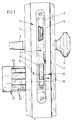
- Fig. 1 einen erfindungsgemäßen Doppel-Schließzylinder, wobei die eine Zylinderseite einen mit Solarzellen bestückten Betätigungsknauf trägt, in eingebautem Zustand in einer mit einem Einsteckschloß, einem Drückerhebel und einem Außenknopf bestückten Türe,
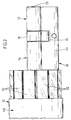
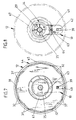
- Fig. 2 den Doppel-Schließzylinder in vergrößerter Einzeldarstellung,
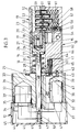
- Fig. 3 einen Längsschnitt durch den Doppel-Schließzylinder gemäß
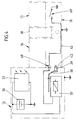
Figur 2, wobei der Betätigungsknauf mittels einer elektromagnetisch arbeitenden Sperr-/Entsperreinrichtung gegen Verdrehen gesichert ist, - Fig. 4 eine schematische Darstellung der elektronischen Schaltung des Doppel-Schließzylinders,
- Fig. 5 eine der
Figur 3 entsprechende Darstellung, jedoch mit einem türaußenseitig eingeführten, richtig codierten Schlüssel, wobei die Sperrung des Betätigungsknaufes gegen Verdrehen aufgelöst ist, - Fig. 6 einen der
Figur 3 einsprechenden, teils im Schnitt dargestellten Doppel-Schließzylinder, wobei der Betätigungsknauf axial auswärts verlagert ist, - Fig. 7 einen Querschnitt durch den Doppel-Schließzylinder gemäß der Linie VII-VII in
Figur 6 und - Fig. 8 einen Querschnitt gemäß Linie VIII-VIII in
Figur 6.
- 1 shows a double locking cylinder according to the invention, one side of the cylinder carrying an actuating knob equipped with solar cells, in the installed state in a door equipped with a mortise lock, a lever handle and an outer button,
- 2 the double locking cylinder in an enlarged individual view,
- 3 shows a longitudinal section through the double locking cylinder according to FIG. 2, the actuating knob being secured against rotation by means of an electromagnetically operating locking / unlocking device,
- 4 is a schematic representation of the electronic circuit of the double locking cylinder,
- 5 shows a representation corresponding to FIG. 3, but with a correctly coded key inserted on the outside of the door, the locking of the actuating knob against twisting being released,
- 6 a double lock cylinder which is in line with FIG. 3 and is partly shown in section, the actuating knob being displaced axially outwards,
- Fig. 7 shows a cross section through the double locking cylinder along the line VII-VII in Figure 6 and
- 8 shows a cross section along line VIII-VIII in FIG. 6.
In der in Figur 1 gezeigten Tür 1 sitzt in ihrer Schloßtasche 2 ein mit dem üblichen Eingerichte versehenes Einsteckschloß 3 ein. Die Falle 4 des Einsteckschlosses 3 wird hierbei in üblicher Weise von einem dem türinnenseitigen Beschlag 5 zugeordneten Drückerhebel 6 betätigt. Dem Außenbeschlag 7 der Tür 1 ist hierbei ein Außenknopf 8 angeformt. Die Verlagerung des Türriegels 9 erfolgt über einen Doppel-Schließzylinder 10, der türaussenseitig über einen Schlüssel 11 und türinnenseitig über einen Betätigungsknauf 12 bedienbar ist.In the
Der Doppel-Schließzylinder 10 besitzt einen asymmetrischen Aufbau und ist derart ausgebildet, daß ein Profilzylinderabschnitt 13 der Türaußenseite und ein Knaufzylinderabschnitt 14 der Türinnenseite zugeordnet ist. Zwischen diesen Zylinderabschnitten 13 und 14 ist in üblicher Weise eine Schließbart-Ausnehmung 15 vorgesehen.The
In der Kernbohrung 16 des Knaufzylinderabschnittes 14 ist in dem, der Schließbart-Ausnehmung 15 zugewandten Endbereich ein zylindrischer Mitnehmerkern 17 angeordnet, der zum Teil aus der Kernbohrung 16 in die Schließbart-Ausnehmung 15 hineinragt und hier eine Schließgliednabe 18 trägt, wobei sich der Mitnehmerkern 17 etwa bis zur Mitte der Schließgliednabe 18 erstreckt. Von der Stirnfläche des die Schließgliednabe 18 tragenden Teilbereichs des Mitnehmerkerns 17 erstreckt sich eine axiale Sackbohrung 19, zur Aufnahme eines in üblicher Weise gestalteten Kupplungsstückes 20. Vor diesem Kupplungsstück 20 liegt eine Spiralfeder 21 in der Sackbohrung 19 ein, die bestrebt ist das Kupplungsstück 20 in Richtung auf den Profilzylinderabschnitt 13 zu verlangern. Die Schließgliednabe 18 und der Mitnehmerkern 17 sind über einen, beide Teile durchdringenden und in einen axialen Längsschlitz 22 des Kupplungsstückes 20 gelagerten Mitnahmestift 23 verbunden. An der dem Knaufzylinderabschnitt 14 zugewandten Seite ist dem Mitnehmerkern 17 ein Steg 24 angeformt. Dieser steht in Eingriff mit einer axial gelagerten Welle 25, die im wesentlichen durchmesserkleiner als der Innendurchmesser der Kernbohrung 16 ausgebildet ist. Lediglich in ihrem dem Mitnehmerkern 17 zugeordneten Ende besitzt die Welle 25 einen dem Innendurchmesser der Kernbohrung 16 entsprechenden Wellenabschnitt 26. Der Eingriff des Steges 24 erfolgt in einem von der Stirnfläche des Wellenabschnittes 26 ausgehenden Aufnahmeschlitz 27, dessen Länge etwas grösser ist als die Länge des Steges 24. Die Lagerung der außerhalb des Knaufzylinderabschnittes 14 zur Aufnahme des Betätigungsknaufes 12 dienenden Welle 25 erfolgt einerseits über den Wellenabschnitt 26 und andererseits über einen in den äußeren Endbereich der Kernbohrung 16 in ein Gewinde eingedrehten, eine dem Durchmesser der Welle 25 entsprechende Axialbohrung 28 aufweisenden Lagerkörper 29. Eine sich an der Innenseite des Lagerkörpers 29 abstützende Druckfeder 30 beaufschlagt hierbei den sich an dem Mitnehmerkern 17 abstützenden Wellenabschnitt 26.In the core bore 16 of the
Der Betätigungsknauf 12 besitzt einen zwölfeckigen Querschnitt, wobei bei jeder Einzelfläche 31′ der Mantelfläche 31 dem Betätigungsknauf 12 Solarzellen 32 zugeordnet sind. Eine der Axialbohrung 33 dient zur Aufnahme der Welle 25, deren mechanische Verbindung mit dem Betätigungsknauf 12 mittels einer dem Betätigungsknauf 12 zugeordneten und die Welle 25 radial beaufschlagenen Klemmschraube 34 realisiert ist. Der Betätigungsknauf 12 besitzt an seiner dem Schließzylinder abgewandten Seite zwei Ausnehmungen. Die eine Ausnehmung dient als Aufnahmefach 35 zur Aufnahme eines Akkus 36. Die andere Ausnehmung dient zur Aufnahme eines Elektromagneten 37 und eines diesem zugeordneten Schwenkhebels 38. Dieser trägt an seinem einen Ende einen Sperrstift 39, der in Grundstellung eine zwischen der Ausnehmung zur Aufnahme des Elektromagneten 37 und der dem Schließzylinder zugewandten Seite des Betätigungsknaufes 12 gebildete Aussparung 40 durchgreift und in eine im Steg 41 des Knaufzylinderabschnittes 14 eingebrachte Sperrnut 42 eintritt. Der Sperrstift 39 wird durch eine, das andere Ende des Schwenkhebels 38 beaufschlagende Druckfeder 43 in seiner Grundstellung gehalten. An seiner dem Schließzylinder gegenüberliegenden Seite besitzt der Betätigungsknauf 12 eine Verschlußkappe 44, die sich aus einem, die mit den Solarzellen 32 bestückte Mantelfläche 31 um wenige Millimeter überragenden Zylinderabschnitt 45 und einer an diesem angeordneten, kreisrunden Abdeckplatte 46 zusammensetzt. Die Abdeckplatte 46 trägt mittig an ihrer Innenseite eine mit einer Bohrung 47 zur Aufnahme einer Befestigungsschraube 48 versehene, zylindrische Anformung 49, die sich in zusammengebautem Zustand an der Stirnfläche der mit dem Betätigungsknauf 12 verbundenen Welle 25 abstützt, wobei die Befestigungsschraube 48 in eine axiale Gewindebohrung 50 der Welle 25 eingedreht ist.The actuating
In dem Profilzylinderabschnitt 13 des Doppel-Schließzylinders 10 ist ein Zylinderkern 51 drehbar gelagert. Im übrigen weist der Profilzylinderabschnitt 13 die üblichen Stiftzuhaltungen 52 auf, die in einer gemeinsamen Gehäusemittelebene liegen, in welcher auch in dem Zylinderkern 51 ein Schlüsselkanal 53 verläuft. Die der Schließbart-Ausnehmung 15 benachbarte, gehäuseseitige Zuhaltungsbohrung 54 ist von der Stegunterseite her bis etwa zur Hälfte der Längserstreckung der Zuhaltungsbohrung 54 erweitert. Diese Erweiterung dient zur Aufnahme eines Isoliermantels 55, in dessen Aufnahmekammer 56 ein federbelasteter Kontakt 57 verschieblich gelagert ist. An der der Zuhaltungsbohrung 54 zugewandten Stirnfläche weist der Isoliermantel 55 eine Durchtrittsöffnung 58 auf, die durchmesserkleiner ist als die Aufnahmekammer 56. Dem Gehäusestift 59 der entsprechenden Stiftzuhaltung 52 ist an seiner Unterseite ein Kontaktdorn 60 angeformt. Dieser ist von einer Spiralfeder 61 umschlossen, die sich einerseits an der Stirnfläche des Isoliermantels 55 und andererseits an der Unterseite des Gehäusestiftes 59 abstützt und dabei bestrebt ist, die Stiftzuhaltung 52 in eine den Zylinderkern 51 sperrende Stellung zu verlagern. Der Kontakt 57 ist über eine in den Schließzylindersteg eingelassene elektrische Leitung 62 mit einem Kontaktstift 63 verbunden. Dieser ist in einem Isoliergehäuse 64 gelagert, wobei dieses in einer von der dem Betätigungsknauf 12 zugewandten Zylindergehäusestirnfläche 65 ausgehenden Sackbohrung 66 einliegt. Der Kontaktstift 63 ist dabei in Richtung auf den Betätigungsknauf 12 federbelastet und durchdringt die Stirnfläche des Isoliergehäuses 64. Die Spitze des Kontaktes 63 stützt sich hierbei auf einen, in die Stirnfläche des Betätigungsknaufes 12 eingelassenen und gegen diesen isolierten, axial ausgerichteten Ringkontakt 67. Diese mit 68 bezeichnete Schleifkontakt-Verbindung stellt nunmehr eine elektrische Verbindung zwischen dem Kontakt 57 des Profilzylinderabschnittes 13 und den Baugruppen im Betätigungsknauf 12 dar.A
Zur Verdeutlichung der elektrischen Vorgänge im Doppel-Schließzylinder 10 dient die in Figur 4 gezeigte Schemadarstellung.The schematic representation shown in FIG. 4 serves to illustrate the electrical processes in the
Die Solarzellen 32 speisen den parallel zu diesen geschalteten Akku 36, dessen Pluspol über eine Leitung mit dem Pluskontakt des Elektromagneten 37 in Verbindung steht. Der Minuskontakt des Elektromagneten 37 ist über die Schleifkontakt-Verbindung 68 mit einem Kontakt des im Profilzylinderabschnitt 13 angeordneten Signalgebers, der in der Schemadarstellung zur Verdeutlichung als einfacher Ein-/Ausschalter 69 dargestellt ist, verbunden. Der andere Kontakt liegt über eine Masseleitung am Minuspol des Akkus 36 an. Die Masseleitung ist in dem beschriebenen Ausführungsbeispiel dadurch realisiert, daß die Leitung des Minuspols des Akkus 36 mit der Welle 25 und über diese mit dem im Schließzylinder gelagerten, nicht isolierten Gehäusestift 59 verbunden ist. Wie in Figur 4 ersichtlich, erzielt ein Schließen des Schaltes 69 eine Schließung des Stromkreises, was zur Folge hat, daß der Elektomagnet 37 anzieht und somit den an dem Schwenkhebel 38 angeordneten Sperrstift 39 aus der Sperrnut 42 herausverlagert.The
Bei Einführen eines richtig codierten Schlüssels 11 in den Schlüsselkanal 53 werden die Stiftzuhaltungen 52 in bekannter Weise verlagert, derart, daß der Zylinderkern 51 frei drehbar ist. Dabei liegt die Schlüsselspitze in einer Ausnehmung des Kupplungsstückes 20 der Schließgliednabe 18 ein. Bei Verlagern der der Schließbart-Ausnehmung 15 benachbarten Stiftzuhaltung durchfährt der Kontaktdorn 60 des Gehäusestiftes 59 die Durchtrittsöffnung 58 des Isoliermantels 55 und beaufschlagt hierbei den federbelasteten Kontakt 57. Dieser Vorgang ist gleichbedeutend mit dem Einschalten des in der Schemazeichnung in Figur 4 gezeigten Schaltes 69 und bewirkt somit ein Verschwenken des an dem Schwenkhebel 38 angeordneten Sperrstiftes 39 in eine Freigabestellung mittels des Elektromagneten 37 (vergleiche Figur 5). Der den Betätigungsknauf 12 über die Welle 25, den Mitnehmerkern 17 und das Kupplungsstück 20 mitschleppende Schlüssel 11 kann nunmehr frei gedreht werden.When a correctly coded key 11 is inserted into the key channel 53, the
Das Einführen eines falsch codierten Schlüssels hat zur Folge, daß der Elektromagnet 37 den Schwenkhebel 38 nicht verlagert und somit der Sperrstift 39 mit der Sperrnut 42 in Eingriff verbleibt. Somit ist der Betätigungsknauf 12 und der indirekt mit diesem in Eingriff stehende Schlüssel nicht drehbar.The introduction of an incorrectly coded key has the result that the
Der Doppel-Schließzylinder kann jederzeit von der Türinnenseite her betätigt werden, indem der Betätigungsknauf 12 axial auswärts, entgegen der Federkraft der Feder 30 verlagert wird und infolge dessen der Sperrstift 39 die Sperrnut 42 verläßt. Der Betätigungsknauf 12 ist nunmehr frei drehbar und somit der Doppel-Schließzylinder 12 betätigbar (vergleiche Figur 6).The double locking cylinder can be actuated from the inside of the door at any time by displacing the actuating
Claims (10)
- Double lock cylinder (10) having a cylinder core (51) which is provided on the one cylinder side and has a key channel (53) and tumblers (52) which make contact with the key (11) and are displaced by the matching key (11) into the release position, and having, arranged between the two cylinders (13, 14), a lock element hub (18), a coupling associated therewith and an electrically operating locking/unlocking device which can be activated by an associated coding of the key (11) and then allows the key to be turned, characterised in that the other cylinder side (14) supports an operating knob (12) which is fitted on its surface with solar cells (32) and, in its interior, has an accumulator (36), supplied from the solar-cell current, as the power supply for the locking/unlocking device.
- Double lock cylinder according to Claim 1, characterised in that the electrically supplied assemblies (electromagnet 37) of the electromagnetically operating locking/unlocking device are also accommodated in the interior of the operating knob (12).
- Double lock cylinder according to one or more of the preceding claims, characterised in that the turning movement of the operating knob (12) can be blocked by a pin (locking pin 39) which extends from the operating knob (12) to the cylinder housing end surface (65) and can be moved into a suitable position both by the attraction force of an electromagnet (37) as well as by an axial outwards displacement of the operating knob (12).
- Double lock cylinder according to one or more of the preceding claims, characterised by a sliding-contact connection (68) between the operating knob (12) and the cylinder housing end surface (65) for transferring the signals which have been scanned from the additional coding of the key (11) into the operating knob (12).
- Double lock cylinder according to one or more of the preceding claims, characterised in that the sliding-contact connection (68) comprises an axially aligned ring contact (67) on the knob side and a contact pin (63) on the cylinder-housing side which makes contact with the ring contact (67).
- Double lock cylinder according to one or more of the preceding claims, characterised in that the contact pin (63) on the cylinder-housing side is spring-loaded in the direction of the ring contact (67) of the operating knob (12).
- Double lock cylinder according to one or more of the preceding claims, characterised by an accumulator receptacle compartment (35) in the operating knob (12), which can be exposed by opening the front plate (closing cap 44) of the operating knob (12).
- Double lock cylinder according to one or more of the preceding claims, characterised in that the operating knob (12) is located on a shaft (25) which extends as far as the coupling for the lock element hub (18) and is sprung axially inwards, and in which a coupling piece (20), which is sprung in the direction of the key channel (53) on the other cylinder side (13) and on which the key tip engages, is supported at the inward end.
- Double lock cylinder according to one or more of the preceding claims, characterised in that the outline surface (31) of the operating knob (12) forms a polygon and the individual surfaces (31′) are each fitted with a solar cell (32).
- Double lock cylinder according to one or more of the preceding claims, characterised in that the outline surface (31) of the preceding knob (12) is constructed as a dodecagon.
Priority Applications (1)
| Application Number | Priority Date | Filing Date | Title |
|---|---|---|---|
| AT90120389T ATE84106T1 (en) | 1989-11-23 | 1990-10-24 | DOUBLE LOCKING CYLINDER. |
Applications Claiming Priority (2)
| Application Number | Priority Date | Filing Date | Title |
|---|---|---|---|
| DE3938791 | 1989-11-23 | ||
| DE3938791A DE3938791A1 (en) | 1989-11-23 | 1989-11-23 | DOUBLE LOCKING CYLINDER |
Publications (3)
| Publication Number | Publication Date |
|---|---|
| EP0428892A2 EP0428892A2 (en) | 1991-05-29 |
| EP0428892A3 EP0428892A3 (en) | 1991-12-18 |
| EP0428892B1 true EP0428892B1 (en) | 1992-12-30 |
Family
ID=6394034
Family Applications (1)
| Application Number | Title | Priority Date | Filing Date |
|---|---|---|---|
| EP90120389A Expired - Lifetime EP0428892B1 (en) | 1989-11-23 | 1990-10-24 | Double cylinder lock |
Country Status (6)
| Country | Link |
|---|---|
| EP (1) | EP0428892B1 (en) |
| AT (1) | ATE84106T1 (en) |
| DE (2) | DE3938791A1 (en) |
| DK (1) | DK0428892T3 (en) |
| ES (1) | ES2037514T3 (en) |
| GR (1) | GR3007503T3 (en) |
Families Citing this family (11)
| Publication number | Priority date | Publication date | Assignee | Title |
|---|---|---|---|---|
| JP3473044B2 (en) * | 1993-04-28 | 2003-12-02 | 株式会社デンソー | Spark plug |
| ATE192207T1 (en) * | 1995-01-24 | 2000-05-15 | Dorma Gmbh & Co Kg | LOCKING MECHANISM FOR A DOOR |
| DE19853207C2 (en) * | 1998-11-18 | 2001-02-01 | Simons & Voss Identifikationss | Locking device |
| DE19940247A1 (en) * | 1999-08-25 | 2001-03-08 | Winkhaus Fa August | Locking device |
| AT409020B (en) * | 1999-11-03 | 2002-05-27 | Roto Frank Eisenwaren | MORE TIE CLOSURE |
| DE60110103T2 (en) | 2000-08-22 | 2006-06-01 | Kowalczyk, Piotr Leonard | LOCK |
| FR2849085A1 (en) * | 2003-04-16 | 2004-06-25 | Reelax France Sa | Lock cylinder, has rotating shaft of pinion extends along central longitudinal axis across opening, where pinion and rotating shaft are connected in rotation by complementary form |
| ES2378765T3 (en) * | 2004-03-11 | 2012-04-17 | Keso Ag | Electromechanical locking cylinder |
| EP1951976A2 (en) * | 2005-11-24 | 2008-08-06 | Palladio Systeme GmbH | Electromechanical locking cylinder and method for controlling the unlocking of an electromechanical locking cylinder |
| AT502682B1 (en) * | 2006-08-07 | 2007-05-15 | Evva Werke | Access control device for door, has lock and key with power supply including thin-film solar cell, which is fitted at area of key and/or part electrically connected to lock, or below energy-transmissive area of lock, key and/or part |
| AT513051B1 (en) * | 2012-09-06 | 2014-01-15 | Evva Sicherheitstechnologie | Locking device with connecting means, which have electrical contacts and mating contacts |
Family Cites Families (4)
| Publication number | Priority date | Publication date | Assignee | Title |
|---|---|---|---|---|
| DE3606531A1 (en) * | 1986-02-28 | 1987-09-03 | Fliether Karl Gmbh & Co | Lock cylinder with drive |
| FR2609090A1 (en) * | 1986-12-29 | 1988-07-01 | Ferraye Joseph | System, for closing or locking any sort of door, which locks the bars with the frame |
| DE3711501A1 (en) * | 1987-04-04 | 1988-10-13 | Heinz Raible | Security lock with plug-in reader for coded card with keyboard - has covering elements protecting coded strip and control unit with read-in disable program |
| DE3712300A1 (en) * | 1987-04-10 | 1988-10-27 | Bks Gmbh | PROFILE LOCKING CYLINDER, ESPECIALLY FOR POCKET LOCKS |
-
1989
- 1989-11-23 DE DE3938791A patent/DE3938791A1/en active Granted
-
1990
- 1990-10-24 EP EP90120389A patent/EP0428892B1/en not_active Expired - Lifetime
- 1990-10-24 DE DE9090120389T patent/DE59000694D1/en not_active Expired - Fee Related
- 1990-10-24 ES ES199090120389T patent/ES2037514T3/en not_active Expired - Lifetime
- 1990-10-24 DK DK90120389.3T patent/DK0428892T3/en active
- 1990-10-24 AT AT90120389T patent/ATE84106T1/en not_active IP Right Cessation
-
1993
- 1993-03-30 GR GR930400688T patent/GR3007503T3/el unknown
Also Published As
| Publication number | Publication date |
|---|---|
| ATE84106T1 (en) | 1993-01-15 |
| EP0428892A2 (en) | 1991-05-29 |
| GR3007503T3 (en) | 1993-08-31 |
| DE59000694D1 (en) | 1993-02-11 |
| DE3938791C2 (en) | 1991-12-12 |
| ES2037514T3 (en) | 1993-06-16 |
| DK0428892T3 (en) | 1993-05-10 |
| DE3938791A1 (en) | 1991-06-06 |
| EP0428892A3 (en) | 1991-12-18 |
Similar Documents
| Publication | Publication Date | Title |
|---|---|---|
| EP1574643B1 (en) | Electromechanical lock cylinder | |
| EP1636454B1 (en) | Electromechanical lock cylinder | |
| DE112007001299B4 (en) | Cam lock with retractable mandrel | |
| EP0462316B1 (en) | Double cylinder lock with electric locking means | |
| EP0428892B1 (en) | Double cylinder lock | |
| EP2239401B1 (en) | Electromechanical rotating closing cylinder | |
| EP2110501B1 (en) | Lock cylinder assembly | |
| EP0995864B1 (en) | Electro-mechanical lock system | |
| EP0324096A2 (en) | Locking cylinder, especially a cylinder for a mortise lock | |
| DE19930054C5 (en) | Electromechanical locking system | |
| EP1155427A1 (en) | Device for receiving and holding an identification provider, such as an electronic key, especially for an ignition-starter switch | |
| EP0668422A1 (en) | Locking mechanism for a lock | |
| DE102004046778B4 (en) | Lock cylinder with increased security | |
| EP0887495B1 (en) | Coupling system for electronic locking devices | |
| EP0805905B1 (en) | Door-closing mechanism | |
| DE10324690A1 (en) | Method for remotely operating a cylinder lock has two separable sections which may be locked together electrically or by means of a key | |
| DE102005034325A1 (en) | Fitting for access control device for door, has housing protrusion facing door panel and designed to fit into cylindrical hole provided for lock cylinder instead of lock cylinder | |
| EP0882858B1 (en) | Lock cylinder with electromagnetically actuated tumbler pin | |
| DE4000643B4 (en) | Door lock, especially mortise lock | |
| EP0709533B1 (en) | Lock cylinder with electromagnetically actuated tumbler pin | |
| AT525744B1 (en) | locking device | |
| AT524794B1 (en) | cylinder lock | |
| DE10258151C1 (en) | Lock cylinder with electronically-controlled coupling allowing cylinder core rotated by inserted key to be coupled to lock nose | |
| DE10311986A1 (en) | lock cylinder | |
| DE10249972A1 (en) | A method for coupling two rotating parts of a cylinder lock has spring loaded plungers whose action is inhibited by a central shaft |
Legal Events
| Date | Code | Title | Description |
|---|---|---|---|
| PUAI | Public reference made under article 153(3) epc to a published international application that has entered the european phase |
Free format text: ORIGINAL CODE: 0009012 |
|
| AK | Designated contracting states |
Kind code of ref document: A2 Designated state(s): AT BE CH DE DK ES FR GB GR IT LI LU NL SE |
|
| PUAL | Search report despatched |
Free format text: ORIGINAL CODE: 0009013 |
|
| AK | Designated contracting states |
Kind code of ref document: A3 Designated state(s): AT BE CH DE DK ES FR GB GR IT LI LU NL SE |
|
| 17P | Request for examination filed |
Effective date: 19920116 |
|
| 17Q | First examination report despatched |
Effective date: 19920424 |
|
| GRAA | (expected) grant |
Free format text: ORIGINAL CODE: 0009210 |
|
| AK | Designated contracting states |
Kind code of ref document: B1 Designated state(s): AT BE CH DE DK ES FR GB GR IT LI LU NL SE |
|
| REF | Corresponds to: |
Ref document number: 84106 Country of ref document: AT Date of ref document: 19930115 Kind code of ref document: T |
|
| ET | Fr: translation filed | ||
| REF | Corresponds to: |
Ref document number: 59000694 Country of ref document: DE Date of ref document: 19930211 |
|
| GBT | Gb: translation of ep patent filed (gb section 77(6)(a)/1977) |
Effective date: 19930222 |
|
| ITF | It: translation for a ep patent filed |
Owner name: STUDIO JAUMANN |
|
| REG | Reference to a national code |
Ref country code: DK Ref legal event code: T3 |
|
| REG | Reference to a national code |
Ref country code: ES Ref legal event code: FG2A Ref document number: 2037514 Country of ref document: ES Kind code of ref document: T3 |
|
| REG | Reference to a national code |
Ref country code: GR Ref legal event code: FG4A Free format text: 3007503 |
|
| PLBE | No opposition filed within time limit |
Free format text: ORIGINAL CODE: 0009261 |
|
| STAA | Information on the status of an ep patent application or granted ep patent |
Free format text: STATUS: NO OPPOSITION FILED WITHIN TIME LIMIT |
|
| EPTA | Lu: last paid annual fee | ||
| 26N | No opposition filed | ||
| EAL | Se: european patent in force in sweden |
Ref document number: 90120389.3 |
|
| PGFP | Annual fee paid to national office [announced via postgrant information from national office to epo] |
Ref country code: SE Payment date: 19971015 Year of fee payment: 8 |
|
| PG25 | Lapsed in a contracting state [announced via postgrant information from national office to epo] |
Ref country code: SE Free format text: LAPSE BECAUSE OF NON-PAYMENT OF DUE FEES Effective date: 19981025 |
|
| PGFP | Annual fee paid to national office [announced via postgrant information from national office to epo] |
Ref country code: GR Payment date: 19981030 Year of fee payment: 9 |
|
| EUG | Se: european patent has lapsed |
Ref document number: 90120389.3 |
|
| PG25 | Lapsed in a contracting state [announced via postgrant information from national office to epo] |
Ref country code: GR Free format text: LAPSE BECAUSE OF NON-PAYMENT OF DUE FEES Effective date: 19991031 |
|
| REG | Reference to a national code |
Ref country code: GB Ref legal event code: IF02 |
|
| PGFP | Annual fee paid to national office [announced via postgrant information from national office to epo] |
Ref country code: FR Payment date: 20051005 Year of fee payment: 16 |
|
| PGFP | Annual fee paid to national office [announced via postgrant information from national office to epo] |
Ref country code: CH Payment date: 20051010 Year of fee payment: 16 Ref country code: DE Payment date: 20051010 Year of fee payment: 16 Ref country code: GB Payment date: 20051010 Year of fee payment: 16 Ref country code: LU Payment date: 20051010 Year of fee payment: 16 Ref country code: DK Payment date: 20051010 Year of fee payment: 16 |
|
| PGFP | Annual fee paid to national office [announced via postgrant information from national office to epo] |
Ref country code: BE Payment date: 20051013 Year of fee payment: 16 Ref country code: NL Payment date: 20051013 Year of fee payment: 16 Ref country code: AT Payment date: 20051013 Year of fee payment: 16 |
|
| PGFP | Annual fee paid to national office [announced via postgrant information from national office to epo] |
Ref country code: ES Payment date: 20051014 Year of fee payment: 16 |
|
| PG25 | Lapsed in a contracting state [announced via postgrant information from national office to epo] |
Ref country code: AT Free format text: LAPSE BECAUSE OF NON-PAYMENT OF DUE FEES Effective date: 20061024 |
|
| PG25 | Lapsed in a contracting state [announced via postgrant information from national office to epo] |
Ref country code: LI Free format text: LAPSE BECAUSE OF NON-PAYMENT OF DUE FEES Effective date: 20061031 Ref country code: DK Free format text: LAPSE BECAUSE OF NON-PAYMENT OF DUE FEES Effective date: 20061031 Ref country code: CH Free format text: LAPSE BECAUSE OF NON-PAYMENT OF DUE FEES Effective date: 20061031 |
|
| PGFP | Annual fee paid to national office [announced via postgrant information from national office to epo] |
Ref country code: IT Payment date: 20061031 Year of fee payment: 17 |
|
| PG25 | Lapsed in a contracting state [announced via postgrant information from national office to epo] |
Ref country code: NL Free format text: LAPSE BECAUSE OF NON-PAYMENT OF DUE FEES Effective date: 20070501 Ref country code: DE Free format text: LAPSE BECAUSE OF NON-PAYMENT OF DUE FEES Effective date: 20070501 |
|
| REG | Reference to a national code |
Ref country code: CH Ref legal event code: PL |
|
| GBPC | Gb: european patent ceased through non-payment of renewal fee |
Effective date: 20061024 |
|
| NLV4 | Nl: lapsed or anulled due to non-payment of the annual fee |
Effective date: 20070501 |
|
| REG | Reference to a national code |
Ref country code: FR Ref legal event code: ST Effective date: 20070629 |
|
| PG25 | Lapsed in a contracting state [announced via postgrant information from national office to epo] |
Ref country code: GB Free format text: LAPSE BECAUSE OF NON-PAYMENT OF DUE FEES Effective date: 20061024 |
|
| BERE | Be: lapsed |
Owner name: KARL *FLIETHER G.M.B.H. & CO. K.G. Effective date: 20061031 |
|
| REG | Reference to a national code |
Ref country code: ES Ref legal event code: FD2A Effective date: 20061025 |
|
| PG25 | Lapsed in a contracting state [announced via postgrant information from national office to epo] |
Ref country code: FR Free format text: LAPSE BECAUSE OF NON-PAYMENT OF DUE FEES Effective date: 20061031 Ref country code: ES Free format text: LAPSE BECAUSE OF NON-PAYMENT OF DUE FEES Effective date: 20061025 |
|
| PG25 | Lapsed in a contracting state [announced via postgrant information from national office to epo] |
Ref country code: LU Free format text: LAPSE BECAUSE OF NON-PAYMENT OF DUE FEES Effective date: 20061024 |
|
| PG25 | Lapsed in a contracting state [announced via postgrant information from national office to epo] |
Ref country code: BE Free format text: LAPSE BECAUSE OF FAILURE TO SUBMIT A TRANSLATION OF THE DESCRIPTION OR TO PAY THE FEE WITHIN THE PRESCRIBED TIME-LIMIT Effective date: 20061031 Ref country code: IT Free format text: LAPSE BECAUSE OF NON-PAYMENT OF DUE FEES Effective date: 20071024 |