EP0428186A1 - Tragbares Motoraggregat - Google Patents
Tragbares Motoraggregat Download PDFInfo
- Publication number
- EP0428186A1 EP0428186A1 EP19900125124 EP90125124A EP0428186A1 EP 0428186 A1 EP0428186 A1 EP 0428186A1 EP 19900125124 EP19900125124 EP 19900125124 EP 90125124 A EP90125124 A EP 90125124A EP 0428186 A1 EP0428186 A1 EP 0428186A1
- Authority
- EP
- European Patent Office
- Prior art keywords
- engine
- housing
- clutch
- vibration
- engine unit
- Prior art date
- Legal status (The legal status is an assumption and is not a legal conclusion. Google has not performed a legal analysis and makes no representation as to the accuracy of the status listed.)
- Granted
Links
Images


Classifications
-
- F—MECHANICAL ENGINEERING; LIGHTING; HEATING; WEAPONS; BLASTING
- F01—MACHINES OR ENGINES IN GENERAL; ENGINE PLANTS IN GENERAL; STEAM ENGINES
- F01N—GAS-FLOW SILENCERS OR EXHAUST APPARATUS FOR MACHINES OR ENGINES IN GENERAL; GAS-FLOW SILENCERS OR EXHAUST APPARATUS FOR INTERNAL-COMBUSTION ENGINES
- F01N13/00—Exhaust or silencing apparatus characterised by constructional features
- F01N13/002—Apparatus adapted for particular uses, e.g. for portable devices driven by machines or engines
-
- F—MECHANICAL ENGINEERING; LIGHTING; HEATING; WEAPONS; BLASTING
- F01—MACHINES OR ENGINES IN GENERAL; ENGINE PLANTS IN GENERAL; STEAM ENGINES
- F01N—GAS-FLOW SILENCERS OR EXHAUST APPARATUS FOR MACHINES OR ENGINES IN GENERAL; GAS-FLOW SILENCERS OR EXHAUST APPARATUS FOR INTERNAL-COMBUSTION ENGINES
- F01N1/00—Silencing apparatus characterised by method of silencing
- F01N1/08—Silencing apparatus characterised by method of silencing by reducing exhaust energy by throttling or whirling
-
- F—MECHANICAL ENGINEERING; LIGHTING; HEATING; WEAPONS; BLASTING
- F02—COMBUSTION ENGINES; HOT-GAS OR COMBUSTION-PRODUCT ENGINE PLANTS
- F02B—INTERNAL-COMBUSTION PISTON ENGINES; COMBUSTION ENGINES IN GENERAL
- F02B63/00—Adaptations of engines for driving pumps, hand-held tools or electric generators; Portable combinations of engines with engine-driven devices
- F02B63/02—Adaptations of engines for driving pumps, hand-held tools or electric generators; Portable combinations of engines with engine-driven devices for hand-held tools
-
- F—MECHANICAL ENGINEERING; LIGHTING; HEATING; WEAPONS; BLASTING
- F02—COMBUSTION ENGINES; HOT-GAS OR COMBUSTION-PRODUCT ENGINE PLANTS
- F02F—CYLINDERS, PISTONS OR CASINGS, FOR COMBUSTION ENGINES; ARRANGEMENTS OF SEALINGS IN COMBUSTION ENGINES
- F02F1/00—Cylinders; Cylinder heads
- F02F1/002—Integrally formed cylinders and cylinder heads
-
- F—MECHANICAL ENGINEERING; LIGHTING; HEATING; WEAPONS; BLASTING
- F02—COMBUSTION ENGINES; HOT-GAS OR COMBUSTION-PRODUCT ENGINE PLANTS
- F02F—CYLINDERS, PISTONS OR CASINGS, FOR COMBUSTION ENGINES; ARRANGEMENTS OF SEALINGS IN COMBUSTION ENGINES
- F02F1/00—Cylinders; Cylinder heads
- F02F1/18—Other cylinders
- F02F1/22—Other cylinders characterised by having ports in cylinder wall for scavenging or charging
-
- F—MECHANICAL ENGINEERING; LIGHTING; HEATING; WEAPONS; BLASTING
- F02—COMBUSTION ENGINES; HOT-GAS OR COMBUSTION-PRODUCT ENGINE PLANTS
- F02F—CYLINDERS, PISTONS OR CASINGS, FOR COMBUSTION ENGINES; ARRANGEMENTS OF SEALINGS IN COMBUSTION ENGINES
- F02F11/00—Arrangements of sealings in combustion engines
-
- F—MECHANICAL ENGINEERING; LIGHTING; HEATING; WEAPONS; BLASTING
- F01—MACHINES OR ENGINES IN GENERAL; ENGINE PLANTS IN GENERAL; STEAM ENGINES
- F01N—GAS-FLOW SILENCERS OR EXHAUST APPARATUS FOR MACHINES OR ENGINES IN GENERAL; GAS-FLOW SILENCERS OR EXHAUST APPARATUS FOR INTERNAL-COMBUSTION ENGINES
- F01N2230/00—Combination of silencers and other devices
- F01N2230/06—Spark arresters
-
- F—MECHANICAL ENGINEERING; LIGHTING; HEATING; WEAPONS; BLASTING
- F01—MACHINES OR ENGINES IN GENERAL; ENGINE PLANTS IN GENERAL; STEAM ENGINES
- F01N—GAS-FLOW SILENCERS OR EXHAUST APPARATUS FOR MACHINES OR ENGINES IN GENERAL; GAS-FLOW SILENCERS OR EXHAUST APPARATUS FOR INTERNAL-COMBUSTION ENGINES
- F01N2590/00—Exhaust or silencing apparatus adapted to particular use, e.g. for military applications, airplanes, submarines
- F01N2590/06—Exhaust or silencing apparatus adapted to particular use, e.g. for military applications, airplanes, submarines for hand-held tools or portables devices
-
- F—MECHANICAL ENGINEERING; LIGHTING; HEATING; WEAPONS; BLASTING
- F01—MACHINES OR ENGINES IN GENERAL; ENGINE PLANTS IN GENERAL; STEAM ENGINES
- F01N—GAS-FLOW SILENCERS OR EXHAUST APPARATUS FOR MACHINES OR ENGINES IN GENERAL; GAS-FLOW SILENCERS OR EXHAUST APPARATUS FOR INTERNAL-COMBUSTION ENGINES
- F01N3/00—Exhaust or silencing apparatus having means for purifying, rendering innocuous, or otherwise treating exhaust
- F01N3/06—Exhaust or silencing apparatus having means for purifying, rendering innocuous, or otherwise treating exhaust for extinguishing sparks
-
- F—MECHANICAL ENGINEERING; LIGHTING; HEATING; WEAPONS; BLASTING
- F02—COMBUSTION ENGINES; HOT-GAS OR COMBUSTION-PRODUCT ENGINE PLANTS
- F02B—INTERNAL-COMBUSTION PISTON ENGINES; COMBUSTION ENGINES IN GENERAL
- F02B75/00—Other engines
- F02B75/02—Engines characterised by their cycles, e.g. six-stroke
- F02B2075/022—Engines characterised by their cycles, e.g. six-stroke having less than six strokes per cycle
- F02B2075/025—Engines characterised by their cycles, e.g. six-stroke having less than six strokes per cycle two
Definitions
- the present invention relates to a portable engine unit, and more particularly to a portable engine unit applicable for a weed cutter, snow blower, etc., and has a housing which is separated along a plane including the axis of rotation of an output shaft of the engine.
- a housing which encloses an engine is divided along a plane orthogonal to the axis of rotation of an output shaft of the engine and provided with two cover casings which are fitted to the opposite sides of the housing.
- cover casings which are fitted to the opposite sides of the housing.
- a prior art portable engine is provided with a plurality of vibration isolators between the engine and a housing of the engine.
- the engine comprises a crankcase enclosing a cantilever crank arm, a recoil starter, a magnet wheel, and a centrifugal clutch comprising a clutch drum and a clutch shoe member. These components are arranged axially in series to constitute the engine.
- the vibration isolators are positioned around the engine gravity center which is usually located in front of the crankcase. In this arrangement, the gravity center of reciprocating parts such as a piston and a piston rod, which are main factors of vibration, are positioned out of an area surrounded by the vibration isolators. As a result, vibration is not effectively prevented.
- the prior art portable engine is equipped with a vibration isolator joint between the centrifugal clutch and a torque transmission shaft which transmits torque generated by the engine through the clutch to a work tool such as a weed cutter.
- a vibration isolator joint between the centrifugal clutch and a torque transmission shaft which transmits torque generated by the engine through the clutch to a work tool such as a weed cutter.
- a special casing is required that increases the manufacturing process and cost as well as the weight of engine.
- FIGs 1 to 3 show the external view of the weed cutter.
- An engine 1 (Fig. 4) is enclosed in a housing 3 which is connected with a weed cutter 5 through a transmission shaft 7 disposed in a connection pipe 9.
- the weed cutter 5 comprises a rotary blade 11 and a bearing member 13 which supports the rotary blade 11 and incorporates bevel gears (not shown) to transmit torque from the transmission shaft 7 to the rotary blade 11.
- the housing 3 is made of synthetic resin and divided into a right housing 15 and a left housing 17 along a boundary plane 19 which includes the axis of rotation of an output shaft (a crank shaft) 21 of the engine 1.
- the right and left housings 15 and 17 are fitted together with screws 23.
- a fuel tank 25 (Fig. 4) is provided at an upper part inside the housing 3.
- the housing 3 is also provided with a hook 27, a front handle 29, and a rear handle 31 comprising a right portion 33 and a left portion 35, all of which will be described later.
- a shoulder band 37 is hooked
- the housing 3 Since the housing 3 is separated into the right and left housings 15 and 17 along the plane 19 including the axis of rotation of crank shaft 21, the engine 1, fuel tank 25, etc., are fixed easily between the right and left housings 15 and 17.
- the number of components which constitute the housing 3 is only two (right and left housings 15 and 17) which is smaller in comparison with a prior art housing so that the engine unit according to the present invention may reduce the manufacturing and assembling process as well as cost.
- FIG. 4 shows the arrangement of engine 1, in which a vibration isolator joint 39, a clutch drum 41, a magnet wheel 43, a recoil starter 45, a crankcase 47, a carburetor 49, and a choke case 51 are disposed axially in series.
- the vibration isolator joint 39 is connected with the transmission shaft 7.
- An engine cylinder 53 is connected to the bottom of crankcase 47.
- a muffler 55 is connected to the rear of cylinder 53.
- An ignition plug 57 is attached to the cylinder 53 and actuated by an ignition coil 59 which is located in the vicinity of the circumference of magnet wheel 43 and generates electric power in response to magnets (not shown) embedded in the periphery of magnet wheel 43.
- the magnet wheel 43 is provided with a plurality of fins 61 for generating airflow.
- the torque of engine 1 is transmitted to the rotary blade 11 via the transmission shaft 7.
- the rear handle 31 is hollow, and the hollow portion forms a suction passage 63.
- An upper end of the passage 63 is open to the engine 1 to receive airflow generated by the fins 61.
- An lower end of the passage 63 communicates with a suction chamber 65.
- An air filter 67 is disposed to cross the suction chamber 65. Due to this, airflow generated by the fins 61 enters into the upper end of passage 63 and into the chamber 65, passes through the air filter 67, and is sucked into the carburetor 49. A suction noise generated by the carburetor 49 is reduced during its propagation through the long passage 63 toward the fins 61 side.
- the periphery of air filter 67 is entirely held by the inner side of housing 3. According to this arrangement, a separate casing for the air filter 67 is not required so that the constitution inside the housing 3 may become simpler, and the size of air filter 67 may be allowed to be larger.
- the engine 1 is supported by the housing 3 through vibration isolators 69, 71, 73, and 75.
- the rubber vibration isolator 69 is sealingly disposed between the periphery of choke case 51 and an inner wall of an opening 77 located at the front end of suction chamber 65.
- the rubber vibration isolators 71 and 73 are received in receiver portions 79 and 81 formed on the inner surface of the casing 3.
- the vibration isolators 71 and 73 receive projections 83 and 85 formed on the surface of crankcase 47.
- the rubber vibration isolator 75 is received in a receiver portion 87 formed on the inner surface of the casing 3.
- the vibration isolator 83 receives in turn a projection 89 formed on the bottom surface of cylinder 53.
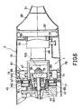
- FIG. 5 shows further detail of the arrangement of engine 1.
- the crankcase 47 has a bearing portion 91 which supports the crank shaft 21 through bearings 93 and 95.
- a piston 97 is slidably enclosed in the cylinder 53 and connected through a piston rod 99 to a crank arm 101 which is fixed to the rear end of crank shaft 21.
- the carburetor 49 is connected to the rear of crankcase 47 through a reed valve 103 (Fig. 6).
- a centrifugal clutch 105 is disposed inside the clutch drum 41. Clutch shoes of the clutch 105 contact with the inner circumference of clutch drum 41 by centrifugal force applied on the clutch shoes due to the rotation of clutch 105.
- the clutch drum 41 may be made by synthetic resin, and may have a metallic friction ring fixed to the inner circumference thereof to contact with the clutch shoes of clutch 105.
- the clutch drum 41, centrifugal clutch 105, and magnet wheel 43 are fixed to the outer end of crank shaft 21 with a female screw cylinder 107.
- the transmission shaft 7 is supported inside the connection pipe 9 through a bearing 109 and a vibration isolator 111.
- a support cylinder 113 is held by the casing 3 at an front end thereof. One end of the connection pipe 9 is inserted into the support cylinder 113.
- the support cylinder 113 is provided with a notch 115 across which a fitting 117 is fixed.
- the fitting 117 is fastened by a bolt 119 to fix the connection pipe 9.
- a cap 121 is fitted such that it covers the fitting 117.
- the support cylinder 113 is provided with a projection 123 which engages with a notch 125 provided at the end of connection pipe 9 to prevent the rotation thereof.
- the vibration isolator joint 39 which is one of features of the present invention will now be described with reference to Fig. 5.
- a boss 127 of the clutch drum 41 engages with the female screw cylinder 107 such that the clutch drum 41 is freely rotatable around the screw cylinder 107.
- An annular member 131 is fixed to the clutch drum 41 of the centrifugal clutch 105.
- a vibration isolator 131 made of resilient material such as rubber is engaged removably into the annular member 131.
- a recess 133 formed on the periphery of vibration isolator 131 engages with a projection 135 formed on the inner surface of the annular member 129 to prevent the relative rotation between them.
- a metallic fitting cylinder 137 is fixed to the center of the vibration isolator 131.
- the fitting cylinder 137 is provided with a hole 139 having a rectangular cross section to receive a rectangular portion 141 located at one end of the transmission shaft 7.
- the torque of engine 1 is transmitted to the transmission shaft 7 through the centrifugal clutch 105, the clutch drum 41, and the vibration isolator joint 39 without propagating the vibration of engine to the transmission shaft 7 and connection pipe 9.
- FIG 5 shows another feature of the present invention, in which an annular baffle 143 is fixed to the casing 3 to cover the front sides of the fins 61.
- the annular baffle 143 guides effectively airflow generated by the fins 61 toward the engine 1.
- a guide plate 145 which is fixed to the housing 3 and extends in a space between the engine 1 and the housing 3 to separate the space.
- the guide plate 145 guides the airflow generated by the fins 61 effectively around the cylinder 53 to cool it.
- the annular baffle 143 may be fixed directly to the peripheries of the fins 61 instead of housing 3 such that it covers the front sides of the fins 61. According to the above arrangement, a part of airflow which tends to flow forward, hits the baffle 143 and is changed its flow direction to the engine 1 side and guided by the guide plate 145 to flow around the cylinder 53.
- the recoil starter 45 will now be described with reference to Figs. 5 and 6.
- the recoil starter 45 is arranged around the bearing portion 91 with a proper gap between them.
- the recoil starter 45 has on its periphery a fitting portion 147 which engages with the housing 3 as well as having on its inner side face projections 149 which engage with the crankcase 47 to prevent the rotation of recoil starter 45.
- a reel 151 of the recoil starter 45 is rotated against the spring force of a spiral spring 153 by pulling a starter handle (not shown) fixed to an end of a starter string 155 which is wound around the reel 151.
- a pivotable nail 157 is arranged on the inner surface of the magnet wheel 43 and pushed by a spring 159 against a ratchet 161 provided on the outer surface of the reel 151.
- the reel 151 and the spiral spring 153 may solidly be made by synthetic resin.
- the reel 151 is rotated to engage the ratchet 161 with the nail portion 157 to rotate the magnet wheel 43. Accordingly, the crank shaft 21 which is fixed to the magnet wheel 43 is rotated to start the engine 1. After that, the nail portion 157 is pushed away by the ratchet 161 to release the engagement between them, and this released state is maintained due to the centrifugal force. If the speed of engine 1 is increased to a predetermined value, the centrifugal clutch 105 is engaged with the clutch drum 41 to transmit torque to the transmission shaft 7 via the vibration isolator joint 39. Since a gap is provided between the bearing portion 91 of crankcase 47 and the recoil starter 45, the heat and vibration of crankcase 47 is not transferred to the recoil starter 45.
- FIG 7 shows that the vibration isolators 69, 71, 73, and 75 shown in Figs. 4 and 6 are located such that the gravity center of the reciprocate portions of engine 1, i.e., the gravity center of the piston 97 and piston rod 99, moves always within a space defined by the positions of the vibration isolators 69, 71, 73, and 75. Due to this arrangement, vibration is effectively prevented.
Landscapes
- Engineering & Computer Science (AREA)
- Chemical & Material Sciences (AREA)
- Combustion & Propulsion (AREA)
- Mechanical Engineering (AREA)
- General Engineering & Computer Science (AREA)
- Harvester Elements (AREA)
Priority Applications (1)
| Application Number | Priority Date | Filing Date | Title |
|---|---|---|---|
| EP90125124A EP0428186B1 (de) | 1985-03-29 | 1986-04-01 | Tragbares Motoraggregat |
Applications Claiming Priority (17)
| Application Number | Priority Date | Filing Date | Title |
|---|---|---|---|
| JP60063814A JPS61226526A (ja) | 1985-03-29 | 1985-03-29 | 携帯用エンジン |
| JP63814/85 | 1985-03-29 | ||
| JP44951/85 | 1985-03-29 | ||
| JP60063815A JPS61224910A (ja) | 1985-03-29 | 1985-03-29 | 携帯用作業機 |
| JP63815/85 | 1985-03-29 | ||
| JP4495185U JPS61162558U (de) | 1985-03-29 | 1985-03-29 | |
| JP57412/85 | 1985-04-19 | ||
| JP57413/85 | 1985-04-19 | ||
| JP5741385U JPS61173741U (de) | 1985-04-19 | 1985-04-19 | |
| JP1985057412U JPH048252Y2 (de) | 1985-04-19 | 1985-04-19 | |
| JP1985061849U JPH064037Y2 (ja) | 1985-04-26 | 1985-04-26 | エンジンの動力伝動装置 |
| JP61846/85 | 1985-04-26 | ||
| JP1985061846U JPH048253Y2 (de) | 1985-04-26 | 1985-04-26 | |
| JP1985061845U JPH0332737Y2 (de) | 1985-04-26 | 1985-04-26 | |
| JP61845/85 | 1985-04-26 | ||
| JP61849/85 | 1985-04-26 | ||
| EP90125124A EP0428186B1 (de) | 1985-03-29 | 1986-04-01 | Tragbares Motoraggregat |
Related Parent Applications (1)
| Application Number | Title | Priority Date | Filing Date |
|---|---|---|---|
| EP86104408.9 Division | 1986-04-01 |
Publications (2)
| Publication Number | Publication Date |
|---|---|
| EP0428186A1 true EP0428186A1 (de) | 1991-05-22 |
| EP0428186B1 EP0428186B1 (de) | 1995-01-18 |
Family
ID=27576086
Family Applications (1)
| Application Number | Title | Priority Date | Filing Date |
|---|---|---|---|
| EP90125124A Expired - Lifetime EP0428186B1 (de) | 1985-03-29 | 1986-04-01 | Tragbares Motoraggregat |
Country Status (1)
| Country | Link |
|---|---|
| EP (1) | EP0428186B1 (de) |
Cited By (3)
| Publication number | Priority date | Publication date | Assignee | Title |
|---|---|---|---|---|
| DE19737657A1 (de) * | 1997-08-29 | 1999-03-04 | Dolmar Gmbh | Verbrennungsmotor und Rahmen für Ansaugtrakt |
| US6196170B1 (en) | 1996-12-27 | 2001-03-06 | Dolmar Gmbh | Driving device for a lawn trimmer |
| US6810849B1 (en) | 1999-01-25 | 2004-11-02 | Briggs & Stratton Corporation | Four-stroke internal combustion engine |
Citations (2)
| Publication number | Priority date | Publication date | Assignee | Title |
|---|---|---|---|---|
| GB2054035A (en) * | 1979-06-25 | 1981-02-11 | Beaird Poulan Div | Portable drive units for power tools |
| US4391041A (en) * | 1981-04-20 | 1983-07-05 | The Toro Company | Powered ground care implement |
Family Cites Families (14)
| Publication number | Priority date | Publication date | Assignee | Title |
|---|---|---|---|---|
| DE1952066A1 (de) * | 1969-10-16 | 1971-06-09 | Stihl Maschf Andreas | Haltevorrichtung fuer Motorsaegen |
| JPS5037294U (de) * | 1973-08-02 | 1975-04-18 | ||
| SE391472B (sv) * | 1973-10-31 | 1977-02-21 | Partner Ab | Anordning vid vibrationsdempade, motordrivna handredskap |
| US3927692A (en) * | 1974-06-28 | 1975-12-23 | American Standard Inc | Four-way poppet valve device |
| DE2623826C2 (de) * | 1976-05-28 | 1984-08-02 | Fa. Andreas Stihl, 7050 Waiblingen | Motorkettensäge |
| DE2911498C2 (de) * | 1979-03-23 | 1987-01-29 | Fa. Andreas Stihl, 7050 Waiblingen | Tragbare Motorkettensäge |
| DE2911497A1 (de) * | 1979-03-23 | 1980-09-25 | Stihl Maschf Andreas | Motorsaege |
| DE3004948A1 (de) * | 1980-02-09 | 1981-08-20 | Solo Kleinmotoren Gmbh, 7032 Sindelfingen | Kombinationsgeraet mit einem arbeitsgeraet und einem verbrennungsmotor |
| ZA814951B (en) * | 1980-08-02 | 1982-08-25 | British Chrome Chemicals Ltd | Productions of chromium trioxide |
| JPS645079Y2 (de) * | 1981-05-25 | 1989-02-08 | ||
| US4422523A (en) * | 1981-12-09 | 1983-12-27 | Kioritz Corporation | Exhaust muffler cover |
| JPS58148231U (ja) * | 1982-03-31 | 1983-10-05 | 小松ゼノア株式会社 | シリンダ−カバ− |
| JPS58173756A (ja) * | 1982-04-06 | 1983-10-12 | Canon Inc | 静電荷像現像用トナー |
| JPS59106794A (ja) * | 1982-12-11 | 1984-06-20 | 三菱重工業株式会社 | 防振構造のエンジン |
-
1986
- 1986-04-01 EP EP90125124A patent/EP0428186B1/de not_active Expired - Lifetime
Patent Citations (2)
| Publication number | Priority date | Publication date | Assignee | Title |
|---|---|---|---|---|
| GB2054035A (en) * | 1979-06-25 | 1981-02-11 | Beaird Poulan Div | Portable drive units for power tools |
| US4391041A (en) * | 1981-04-20 | 1983-07-05 | The Toro Company | Powered ground care implement |
Cited By (4)
| Publication number | Priority date | Publication date | Assignee | Title |
|---|---|---|---|---|
| US6196170B1 (en) | 1996-12-27 | 2001-03-06 | Dolmar Gmbh | Driving device for a lawn trimmer |
| DE19737657A1 (de) * | 1997-08-29 | 1999-03-04 | Dolmar Gmbh | Verbrennungsmotor und Rahmen für Ansaugtrakt |
| DE19737657B4 (de) * | 1997-08-29 | 2006-04-20 | Dolmar Gmbh | Tragbares Handarbeitsgerät und Rahmen für Handarbeitsgerät |
| US6810849B1 (en) | 1999-01-25 | 2004-11-02 | Briggs & Stratton Corporation | Four-stroke internal combustion engine |
Also Published As
| Publication number | Publication date |
|---|---|
| EP0428186B1 (de) | 1995-01-18 |
Similar Documents
| Publication | Publication Date | Title |
|---|---|---|
| US4821691A (en) | Portable engine unit | |
| US5345684A (en) | Flexible line trimmer having an anti-vibration handle | |
| EP1215379B1 (de) | Motorgenerator | |
| US4391041A (en) | Powered ground care implement | |
| JP2501215Y2 (ja) | 背負式動力作業機械 | |
| US4815430A (en) | Portable engine unit | |
| RU2675132C2 (ru) | Рабочий инструмент, направляемый вручную | |
| JP2015008693A (ja) | エンジン作業機 | |
| EP0428186A1 (de) | Tragbares Motoraggregat | |
| US20030154946A1 (en) | Engine operated machine system | |
| GB2098272A (en) | Portable two-stroke engine chain saw | |
| US4798182A (en) | Portable engine | |
| US6592059B2 (en) | Foreign matter entanglement-preventing device in working engine | |
| JPS6321362Y2 (de) | ||
| US4744337A (en) | Portable engine | |
| JP2013021979A (ja) | 刈払機 | |
| EP0221393A1 (de) | Tragbarer Motor | |
| JPH0352979Y2 (de) | ||
| JPH048253Y2 (de) | ||
| JPS59108826A (ja) | 刈払機用2サイクルエンジン | |
| JPH0639547Y2 (ja) | 防振内蔵形駆動装置 | |
| JPH021454Y2 (de) | ||
| JPH0229224Y2 (de) | ||
| GB2187664A (en) | Hand-holdable drilling machine | |
| JP2017190757A (ja) | エンジン作業機 |
Legal Events
| Date | Code | Title | Description |
|---|---|---|---|
| PUAI | Public reference made under article 153(3) epc to a published international application that has entered the european phase |
Free format text: ORIGINAL CODE: 0009012 |
|
| 17P | Request for examination filed |
Effective date: 19901221 |
|
| AC | Divisional application: reference to earlier application |
Ref document number: 197487 Country of ref document: EP |
|
| AK | Designated contracting states |
Kind code of ref document: A1 Designated state(s): DE FR GB |
|
| RIN1 | Information on inventor provided before grant (corrected) |
Inventor name: OONIWA, TAKASHI Inventor name: IRAMINA, KEIKO, 7-1202 SAKURAGAOKA-DANCHI Inventor name: GAMOH, AKIRA Inventor name: INOMATA, HIDEKO Inventor name: KIYOOKA, KATSUMI Inventor name: UENO, TETSUO |
|
| 17Q | First examination report despatched |
Effective date: 19920710 |
|
| GRAA | (expected) grant |
Free format text: ORIGINAL CODE: 0009210 |
|
| AC | Divisional application: reference to earlier application |
Ref document number: 197487 Country of ref document: EP |
|
| AK | Designated contracting states |
Kind code of ref document: B1 Designated state(s): DE FR GB |
|
| REF | Corresponds to: |
Ref document number: 3650213 Country of ref document: DE Date of ref document: 19950302 |
|
| ET | Fr: translation filed | ||
| PLBE | No opposition filed within time limit |
Free format text: ORIGINAL CODE: 0009261 |
|
| STAA | Information on the status of an ep patent application or granted ep patent |
Free format text: STATUS: NO OPPOSITION FILED WITHIN TIME LIMIT |
|
| 26N | No opposition filed | ||
| PGFP | Annual fee paid to national office [announced via postgrant information from national office to epo] |
Ref country code: GB Payment date: 19970319 Year of fee payment: 12 |
|
| PGFP | Annual fee paid to national office [announced via postgrant information from national office to epo] |
Ref country code: FR Payment date: 19970416 Year of fee payment: 12 |
|
| PGFP | Annual fee paid to national office [announced via postgrant information from national office to epo] |
Ref country code: DE Payment date: 19970528 Year of fee payment: 12 |
|
| PG25 | Lapsed in a contracting state [announced via postgrant information from national office to epo] |
Ref country code: GB Free format text: LAPSE BECAUSE OF NON-PAYMENT OF DUE FEES Effective date: 19980401 |
|
| PG25 | Lapsed in a contracting state [announced via postgrant information from national office to epo] |
Ref country code: FR Free format text: THE PATENT HAS BEEN ANNULLED BY A DECISION OF A NATIONAL AUTHORITY Effective date: 19980430 |
|
| GBPC | Gb: european patent ceased through non-payment of renewal fee |
Effective date: 19980401 |
|
| PG25 | Lapsed in a contracting state [announced via postgrant information from national office to epo] |
Ref country code: DE Free format text: LAPSE BECAUSE OF NON-PAYMENT OF DUE FEES Effective date: 19990202 |
|
| REG | Reference to a national code |
Ref country code: FR Ref legal event code: ST |