EP0420589B1 - Verfahren zum Herstellen einer abgeschiedenen Schicht und Verfahren zum Herstellen einer Halbleitervorrichtung - Google Patents
Verfahren zum Herstellen einer abgeschiedenen Schicht und Verfahren zum Herstellen einer Halbleitervorrichtung Download PDFInfo
- Publication number
- EP0420589B1 EP0420589B1 EP90310500A EP90310500A EP0420589B1 EP 0420589 B1 EP0420589 B1 EP 0420589B1 EP 90310500 A EP90310500 A EP 90310500A EP 90310500 A EP90310500 A EP 90310500A EP 0420589 B1 EP0420589 B1 EP 0420589B1
- Authority
- EP
- European Patent Office
- Prior art keywords
- substrate
- film
- molybdenum
- aluminium
- temperature
- Prior art date
- Legal status (The legal status is an assumption and is not a legal conclusion. Google has not performed a legal analysis and makes no representation as to the accuracy of the status listed.)
- Expired - Lifetime
Links
Images


Classifications
-
- H—ELECTRICITY
- H01—ELECTRIC ELEMENTS
- H01L—SEMICONDUCTOR DEVICES NOT COVERED BY CLASS H10
- H01L21/00—Processes or apparatus adapted for the manufacture or treatment of semiconductor or solid state devices or of parts thereof
-
- H—ELECTRICITY
- H01—ELECTRIC ELEMENTS
- H01L—SEMICONDUCTOR DEVICES NOT COVERED BY CLASS H10
- H01L21/00—Processes or apparatus adapted for the manufacture or treatment of semiconductor or solid state devices or of parts thereof
- H01L21/70—Manufacture or treatment of devices consisting of a plurality of solid state components formed in or on a common substrate or of parts thereof; Manufacture of integrated circuit devices or of parts thereof
- H01L21/71—Manufacture of specific parts of devices defined in group H01L21/70
- H01L21/768—Applying interconnections to be used for carrying current between separate components within a device comprising conductors and dielectrics
- H01L21/76838—Applying interconnections to be used for carrying current between separate components within a device comprising conductors and dielectrics characterised by the formation and the after-treatment of the conductors
- H01L21/76841—Barrier, adhesion or liner layers
- H01L21/76843—Barrier, adhesion or liner layers formed in openings in a dielectric
-
- H—ELECTRICITY
- H01—ELECTRIC ELEMENTS
- H01L—SEMICONDUCTOR DEVICES NOT COVERED BY CLASS H10
- H01L21/00—Processes or apparatus adapted for the manufacture or treatment of semiconductor or solid state devices or of parts thereof
- H01L21/02—Manufacture or treatment of semiconductor devices or of parts thereof
- H01L21/04—Manufacture or treatment of semiconductor devices or of parts thereof the devices having at least one potential-jump barrier or surface barrier, e.g. PN junction, depletion layer or carrier concentration layer
- H01L21/18—Manufacture or treatment of semiconductor devices or of parts thereof the devices having at least one potential-jump barrier or surface barrier, e.g. PN junction, depletion layer or carrier concentration layer the devices having semiconductor bodies comprising elements of Group IV of the Periodic System or AIIIBV compounds with or without impurities, e.g. doping materials
- H01L21/28—Manufacture of electrodes on semiconductor bodies using processes or apparatus not provided for in groups H01L21/20 - H01L21/268
- H01L21/283—Deposition of conductive or insulating materials for electrodes conducting electric current
- H01L21/285—Deposition of conductive or insulating materials for electrodes conducting electric current from a gas or vapour, e.g. condensation
- H01L21/28506—Deposition of conductive or insulating materials for electrodes conducting electric current from a gas or vapour, e.g. condensation of conductive layers
- H01L21/28512—Deposition of conductive or insulating materials for electrodes conducting electric current from a gas or vapour, e.g. condensation of conductive layers on semiconductor bodies comprising elements of Group IV of the Periodic System
- H01L21/28556—Deposition of conductive or insulating materials for electrodes conducting electric current from a gas or vapour, e.g. condensation of conductive layers on semiconductor bodies comprising elements of Group IV of the Periodic System by chemical means, e.g. CVD, LPCVD, PECVD, laser CVD
- H01L21/28562—Selective deposition
-
- H—ELECTRICITY
- H01—ELECTRIC ELEMENTS
- H01L—SEMICONDUCTOR DEVICES NOT COVERED BY CLASS H10
- H01L21/00—Processes or apparatus adapted for the manufacture or treatment of semiconductor or solid state devices or of parts thereof
- H01L21/02—Manufacture or treatment of semiconductor devices or of parts thereof
- H01L21/04—Manufacture or treatment of semiconductor devices or of parts thereof the devices having at least one potential-jump barrier or surface barrier, e.g. PN junction, depletion layer or carrier concentration layer
- H01L21/18—Manufacture or treatment of semiconductor devices or of parts thereof the devices having at least one potential-jump barrier or surface barrier, e.g. PN junction, depletion layer or carrier concentration layer the devices having semiconductor bodies comprising elements of Group IV of the Periodic System or AIIIBV compounds with or without impurities, e.g. doping materials
- H01L21/28—Manufacture of electrodes on semiconductor bodies using processes or apparatus not provided for in groups H01L21/20 - H01L21/268
- H01L21/283—Deposition of conductive or insulating materials for electrodes conducting electric current
- H01L21/285—Deposition of conductive or insulating materials for electrodes conducting electric current from a gas or vapour, e.g. condensation
- H01L21/28506—Deposition of conductive or insulating materials for electrodes conducting electric current from a gas or vapour, e.g. condensation of conductive layers
- H01L21/28512—Deposition of conductive or insulating materials for electrodes conducting electric current from a gas or vapour, e.g. condensation of conductive layers on semiconductor bodies comprising elements of Group IV of the Periodic System
- H01L21/28568—Deposition of conductive or insulating materials for electrodes conducting electric current from a gas or vapour, e.g. condensation of conductive layers on semiconductor bodies comprising elements of Group IV of the Periodic System the conductive layers comprising transition metals
-
- H—ELECTRICITY
- H01—ELECTRIC ELEMENTS
- H01L—SEMICONDUCTOR DEVICES NOT COVERED BY CLASS H10
- H01L21/00—Processes or apparatus adapted for the manufacture or treatment of semiconductor or solid state devices or of parts thereof
- H01L21/70—Manufacture or treatment of devices consisting of a plurality of solid state components formed in or on a common substrate or of parts thereof; Manufacture of integrated circuit devices or of parts thereof
- H01L21/71—Manufacture of specific parts of devices defined in group H01L21/70
- H01L21/768—Applying interconnections to be used for carrying current between separate components within a device comprising conductors and dielectrics
- H01L21/76838—Applying interconnections to be used for carrying current between separate components within a device comprising conductors and dielectrics characterised by the formation and the after-treatment of the conductors
- H01L21/76877—Filling of holes, grooves or trenches, e.g. vias, with conductive material
- H01L21/76879—Filling of holes, grooves or trenches, e.g. vias, with conductive material by selective deposition of conductive material in the vias, e.g. selective C.V.D. on semiconductor material, plating
-
- H—ELECTRICITY
- H01—ELECTRIC ELEMENTS
- H01L—SEMICONDUCTOR DEVICES NOT COVERED BY CLASS H10
- H01L2924/00—Indexing scheme for arrangements or methods for connecting or disconnecting semiconductor or solid-state bodies as covered by H01L24/00
- H01L2924/0001—Technical content checked by a classifier
- H01L2924/0002—Not covered by any one of groups H01L24/00, H01L24/00 and H01L2224/00
-
- Y—GENERAL TAGGING OF NEW TECHNOLOGICAL DEVELOPMENTS; GENERAL TAGGING OF CROSS-SECTIONAL TECHNOLOGIES SPANNING OVER SEVERAL SECTIONS OF THE IPC; TECHNICAL SUBJECTS COVERED BY FORMER USPC CROSS-REFERENCE ART COLLECTIONS [XRACs] AND DIGESTS
- Y10—TECHNICAL SUBJECTS COVERED BY FORMER USPC
- Y10S—TECHNICAL SUBJECTS COVERED BY FORMER USPC CROSS-REFERENCE ART COLLECTIONS [XRACs] AND DIGESTS
- Y10S148/00—Metal treatment
- Y10S148/107—Melt
Definitions
- This invention relates to a method for forming deposited film and a method for forming a semiconductor device. Particularly, it pertains to a method for forming an Mo deposited film preferably applied to wiring of a semiconductor circuit device, etc. and a semiconductor device using deposited Mo film.
- Al aluminium
- Al-Si etc. have been used primarily for electrodes and wiring.
- Al is inexpensive and has high electroconductivity, and dense oxidized film can be formed on the surface. Accordingly, it has many advantages since its inner portion can be protected and stabilised, and adhesion to Si is good.
- the self-alignment technique in which mask matching between the gate electrode and the diffusion layer, etc. is unnecessary, is indispensable. No metal having a low melting point such as Al can be used.
- gate electrode wiring capable of self-alignment a polycrystalline Si doped with an impurity at high concentration has been widely employed.
- electrical resistance of fine polycrystalline Si wiring, etc. becomes higher. This is vital to high speed actuation of the device.
- Deposition methods such as electron beam deposition and sputtering have been employed for Mo film used in Mo electrodes wiring, etc.
- the surface of LSI, etc. is subject to excessive unevenness due to oxidation, diffusion, thin film deposition, and etching, etc.
- electrodes or wiring metal must be deposited on the surface with a stepped difference, or deposited in a via-hole which is small in diameter and deep.
- the aspect ratio (via hole depth/via hole diameter) of via-hole in which a wiring metal is to be deposited is 1.0 or more, and the via-hole diameter itself also becomes 1 ⁇ m or less. Therefore, for a via-hole with large aspect ratio, a technique which can deposit wiring metal is required.
- a metal is required to be deposited so as to embed only the via-hole of the device.
- a method of depositing a wiring metal only on Si or metal surface and not on an insulating film such as SiO2, etc. is required.
- the sputter process is a physical deposition method performed by scattering the particles sputtered in vacuum. Therefore, the film thickness becomes very thin at the step portion and insulating film side wall, and breaking of wire may be caused in an extreme case. Further, unevenness of film thickness and the breaking of wire cause remarkable degradation of the reliability of LSI.
- CVD Chemical Vapor Deposition
- plasma CVD or optical CVD decomposition of the starting gas occurs in gas phase, and the active species formed there further react on the substrate to give rise to film formation.
- surface coverage on unevenness on the substrate surface is good since the reaction occurs in a gaseous phase.
- carbon atoms contained in the starting gas molecule are incorporated into the film.
- plasma CVD the problem has remained that there is damage by charged particles (so called plasma damage) as in the case of the sputtering method.
- the thermal CVD method in which the film grows through the surface reaction primarily on the substrate surface, is good in surface coverage on unevenness such as stepped portion of the surface, etc. Also, it can be expected that deposition within via-holes will readily occur. Further, wire breaking at the stepped portion can be avoided.
- WO 86/06755 describes a selective deposition method for depositing tungsten or molybdenum on a patterned substrate. Deposition is conducted in a cold wall reaction chamber at a substrate temperature above 100°C. and the substrate is isolated from impinging radiation. In the examples described tungsten hexafluoride is reduced in an hydrogen atmosphere. It is suggested that Mo(CO)6, MoF6 or MoCl5 may be used for deposition of molybdenum but no specific details are given. The method is said to be applicable to a wide variety of conductor and semiconductor surfaces, e.g. metals, alloyed metals such as platinum, molybdenum, titanium, tungsten, tantalum, aluminium metals and mixtures thereof, also transition metal silicides.
- conductor and semiconductor surfaces e.g. metals, alloyed metals such as platinum, molybdenum, titanium, tungsten, tantalum, aluminium metals and mixtures thereof, also transition metal silicides.
- the deposition methods of Mo film of the prior art have many and various problems requiring solution such as coverage of the stepped difference of the LSI surface is poor, the Si surface of LSI is unnecessarily etched, damage is given to Si02, deposition reaction can be controlled only with difficulty, and a large amount of impurities are mixed into Mo film.
- a deposited film formation method in accordance with the present invention is set out in claim 1 of the claims appended.
- the Mo film obtained by this deposited film formation method contains little impurity such as carbon, etc. Also, the substrate is free from damage and the method is good in controllability. A low resistance, dense Mo film can be selectively deposited on the substrate.
- a method for preparing a semiconductor device in accordance with the present invention is set out in claim 10 of the claims appended.
- an organic Mo compound and H2 gases are employed as the starting gases for deposited film formation.
- Mo(CH3)6 as the organic Mo compound, which is solid at room temperature and carrying it in a carrier gas such as H2, Ar, etc. to a heated substrate
- Mo film is deposited upon reaction with hydrogen gas which also is supplied.
- the detailed mechanism of the reaction has not been clarified, but it may be considered that Mo(CH3)6, etc. reacts with H2 gas on an electron donative substrate surface such as heated metal or semiconductor to form Mo. Since this reaction can proceed only with difficulty at the place where the substrate surface is not electron donative, it may be considered that deposition of the film occurs only with difficulty on an electron non-donative surface.
- An electron donative material refers to one having free electrons existing or free electrons intentionally formed in the substrate, for example, a material having a surface on which the chemical reaction is promoted through give-and-take of electrons with the starting gas molecules attached on the substrate surface.
- a material having a surface on which the chemical reaction is promoted through give-and-take of electrons with the starting gas molecules attached on the substrate surface For example, generally metals and semiconductors correspond to such material.
- Those having very thin oxidized film on the metal or semiconductor surface are also included. For, with such very thin oxidised film, the chemical reaction can occur between the substrate and the attached starting molecules.
- semiconductors such as single crystalline silicon, polycrystalline silicon, amorphous silicon, etc., binary system or ternary system or quaternary system III-V compound semiconductors comprising combinations of Ga, In, Al as the group III element and P, As, N as the group V element, or II-VI compound semiconducters, or metals themselves such as tungsten, molybdenum, tantalum,aluminium , titanium, copper, etc., or silicides of the above metals such as tungsten silicide, molybdenum silicide, tantalum silicide, aluminum silicide, titanium silicide, etc., further metals containing either one of the constituent of the above metals such as aluminium silicon, aluminium titanium, aluminium copper, aluminium tantalum, aluminium silicon copper, aluminium silicon titanium, aluminium palladium, titanium nitride, etc.
- semiconductors such as single crystalline silicon, polycrystalline silicon, amorphous silicon, etc., binary system or ternary system or quaternary
- the materials for forming the surface on which Mo is not deposited selectively are conventional insulating materials, oxidized silicon formed by thermal oxidation, CVD, etc., glass or oxidized film such as BSG, PSG, BPSG, etc., thermally nitrided film, silicon nitrided film by plasma CVD, low pressure CVD, ECR-CVD method, etc.
- Fig. 1 is a schematic view showing a deposition film forming apparatus for applying the present invention.
- 1 is a substrate for forming Mo film.
- the substrate 1 is mounted on a substrate holder 3 provided internally of the reaction tube 2 for forming a space for formation of a deposited film which is substantially closed as shown in Fig. 1.
- quartz is preferable, but it may be also made of a metal.
- the substrate holder 3 is made of a metal, and is provided with a heater 4 so that the substrate mounted thereon can be heated. And, the constitution is made so that the substrate temperature can be controlled by controlling the heat generation temperature of the heater 4.
- the feeding system of gases is constituted as described below.
- 5 is a gas mixer, in which the starting gas (Mo(CH3)6) and the reaction gas (H2) are mixed, and the mixture is fed into the reaction tube 2.
- 6 is a starting gas gasifier provided for gasification of an organic metal as the starting gas.
- the organic metal to be used in the present invention is solid at room temperature, and is formed into saturated vapour by sublimating the organic metal by passing a carrier gas through around the metal within the gasifier 6, which is in turn introduced into the mixer 5.
- the sublimation is markedly accelerated by heating the gas or organic metal itself.
- the evacuation system is constituted as described below.
- a gate valve which is opened when performing evacuation of a large volume such as during evacuation internally of the reaction tube 2 before formation of the deposited film.
- 8 is a slow leak valve, which is used when performing evacuation of a small volume such as in controlling the pressure internally of the reaction tube 2 during formation of the deposited film.
- 9 is an evacuation unit, which is constituted of a pump for evacuation such as turbo molecular pump, etc.
- the conveying system of the substrate 1 is constituted as described below.
- 10 is a substrate conveying chamber which can house the substrate before and after formation of the deposited film, which is evacuated by opening the valve 11.
- 12 is an evacuation unit for evacuating the conveying chamber, which is constituted of a pump for evacuation such as turbo molecular pump, etc.
- the valve 13 is opened only when the substrate 1 is transferred between the reaction chamber and the conveying space.
- the gas formation chamber 6 for forming the starting gas for example, the gas formation chamber 6 is maintained at room temperature or the heated solid organic Mo compound (Mo(CH3)6) is bubbled with H2 or Ar (or other inert gas) as the carrier gas to form gaseous organic Mo compound, which is transported to the mixer 5.
- H2 gas as the reaction gas is transported through another route into the mixer 5.
- the gases are controlled in flow rates so that the respective partial pressures may become desired values.
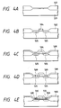
- Figs. 2A to 2E are schematic views showing the state of growing an Mo film.
- Fig. 2A is an illustration showing schematically the cross-section of the substrate before formation of the Mo deposited film according to the present invention.
- 90 is the substrate comprising an electron donative material, and 91 a thin film comprising an electron non-donative material.
- the deposited film thus formed has a resistivity of, for example, with a film thickness of 60 nm (600 ⁇ ), 8-30 ⁇ ohm ⁇ cm at room temperature which is close to the bulk resistivity of Mo and lower than the resistivity of polycrystalline Si, and becomes continuous and flat film.
- the reflectance in the visible wavelength region is approximately 70-80%, and a thin film with excellent surface flatness can be deposited.
- the substrate temperature in forming deposited film should be desirably in the range between the decomposition temperature of the starting gas (Mo(CH3)6) or higher, and 800°C or lower, but specifically a substrate temperature of 350-550°C is desirable.
- a more preferable substrate temperature condition is 400°C to 500°C.
- the Mo film deposited under this condition contains no carbon and oxygen and is sufficiently low in electrical resistance.
- Mo can be deposited on only one sheet of substrate in deposition for one time. Although a deposition speed of ca. 10 nm/min (100 ⁇ /min) can be obtained, it is still insufficient for performing deposition of a large number of sheets within a short time.
- the deposition film forming apparatus for improving this point, there is the low pressure CVD apparatus which can deposit Mo by simultaneous mounting of a large number of sheets of wafer. Since the Mo deposition according to the present invention utilises the surface reaction of the heated electron donative substrate surface, for example, in the hot wall type low pressure CVD method wherein only the substrate is heated, Mo can be desirably deposited.
- Fig. 3 is a schematic view showing a deposited film formation apparatus to which such present invention is applicable.
- 57 is a substrate for forming an Mo film.
- 50 is an outside reaction tube made of quartz for forming a space for formation of deposited film which is substantially closed with respect to surrounding.
- 51 is an inside reaction tube made of quartz located for separation of the gas flow within the outside reaction tube 50, 54 a flange made of a metal for opening and closing the opening of the outside reaction tube 50, and the substrate 57 is located within the substrate holding member 56 provided internally of the inside reaction tube 51.
- the substrate holding member 56 should be desirably made of quartz.
- the present apparatus can control the substrate temperature by the heater portion 59. It is constituted so that the pressure internally of the reaction tube 50 is controllable by the evacuation system bound through the gas evacuation outlet 53.
- the present apparatus has a first gas system, a second gas system and a mixer (all are not shown) similarly as in the apparatus shown in Fig. 1, and the starting gases are introduced into the reaction tube 50 through the starting gas introducing inlet 52.
- the starting gases react on the surface of the substrate 57 when passing through the inner portion of the inside reaction tube 51 as shown by the arrowhead 58 in Fig. 3 to deposit Mo on the substrate surface 57.
- the gases after the reaction pass through the gap portion formed by the inside reaction tube 51 and the outside reaction tube 50 and are discharged through the gas discharging outlet 53.
- the flange 54 made of a metal is ascended and descended by an elevator (not shown) together with the substrate holding member 56 and the substrate 57 to move to a predetermined position, thereby performing attachment and detachment of the substrate.
- Mo film of good quality can be formed at the same time in all the wafers within the apparatus.
- the procedure for Mo film formation is as follows.
- the reaction tube 2 is internally evacuated to ca.1x10 ⁇ 6Pa (1x10 ⁇ 8 Torr) by the evacuation unit 9.
- Mo film can be also formed if the vacuum degree within the reaction tube 2 may be worse than 1x10 ⁇ 6Pa (1x10 ⁇ 8 Torr).
- the conveying chamber 10 was released to atmospheric pressure and Si wafer was mounted in the conveying chamber.
- the conveying chamber was evacuated to ca. 1x10 ⁇ 4Pa (1x10 ⁇ 6 Torr), and then the gate valve 13 was opened and the substrate was mounted on the wafer holder 3.
- the gate valve 13 was closed, and the reaction chamber 2 was evacuated to a vacuum degree of ca. 1x10 ⁇ 6Pa (1x10 ⁇ 8 Torr).
- Mo(CH3)6 was sublimed to feed through the first gas line.
- H2 was used to the carrier gas of Mo(CH3)6 line.
- the second gas line was used for H2.
- the pressure within the reaction tube 2 was made a predetermined value by controlling the opening of the slow leak valve 8. Then, the substrate was heated by current passage through the heater 4. After the substrate temperature has reached a predetermined temperature, Mo(CH3)6 partial pressure was made ca. 2.7x10 ⁇ Pa (2.0 x 1- ⁇ 4 Torr). Next, when Mo(CH3)6 was introduced into the reaction tube through the Mo(CH3)6 line. Here the total pressure was ca. 2.7x10Pa (2.0 Torr) within the reaction tube, and the Mo(CH3)6 was introduced into the reaction tube 2, Mo was deposited. After a predetermined deposition time has elapsed, feeding of Mo(CH3)6 was stopped. Next, heating of the heater 4 was stopped to cool the substrate. Feeding of H2 gas was stopped, and after evacuation internally of the reaction tube, the substrate was transferred to the conveying chamber, and only the conveying chamber was made atmospheric before taking out the substrate. The outline of Mo film formation is as described above.
- the Mo films deposited by varying the substrate temperature were evaluated by use of various evaluation methods, and it was found that in the temperature range of the substrate temperature from 350°C to 550°C, Mo thin films containing very little carbon impurity and having low electrical resistance were deposited with good selectivity on the substrate.
- Si substrates (N type, 1 - 2 ohm.cm) were subjected to thermal oxidation at a temperature of 1000°C according to the hydrogen combustion system (H2: 4 litres/M, 02: 2 litres/M).
- the film thickness was 700 ⁇ 50nm (7000 ⁇ 500 ⁇ ) and the refractive index 1.46.
- a photoresist was coated on the whole Si substrate, and a desired pattern was baked by an exposure machine. The pattern was such that various holes of 0.25 ⁇ m x 0.25 ⁇ m - 100 ⁇ m x 100 ⁇ m were opened.
- the subbing Si02 was etched by the reactive ion etching (RIE), etc. to have the substrate Si partially exposed.
- RIE reactive ion etching
- the samples having various sizes of Si02holes of 0.25 ⁇ m x 0.25 ⁇ m - 100 ⁇ m x 100 ⁇ m were prepared.
- the deposited film was formed on the samples thus formed similarly as in Example 1. Specifically the substrate temperature was changed to a temperature in the range 350°C to 550°C and Mo film was deposited according to the procedure as described above under the following conditions:
- the Mo films deposited by varying the substrate temperature were evaluated, and it was found that in the temperature range of the substrate temperature from 350°C to 550°C, Mo thin films containing very little carbon impurity and having low electrical resistance were deposited with good selectivity on the substrate.
Claims (12)
- Verfahren zur Herstellung einer abgeschiedenen Schicht, das die nachstehenden Schritte umfaßt:Bereitstellung eines Substrats mit einer Oberfläche aus Metall oder einem halbleitenden Material, aus Metall oder einem halbleitenden Material mit einer sehr dünnen oxidierten Schicht darauf, oder aus Wolframsilicid, Molybdänsilicid, Tantalsilicid, Aluminiumsilicid oder Titansilicid; Zufuhr von Hexamethylmolybdängas Mo(CH₃)₆ und Wasserstoffgas an die Oberfläche des Substrats; undHalten der Temperatur der Oberfläche des Substrats innerhalb eines Temperaturbereichs zwischen der Zersetzungstemperatur des Hexamethylmolybdäns und 800 °C, um eine Molybdänschicht auf der Oberfläche des Substrats zu bilden.
- Verfahren nach Anspruch 1, wobei die Oberfläche des Substrats aus einem Metall besteht, das aus Wolfram, Molybdän, Tantal, Aluminium, Titan und Kupfer ausgewählt ist.
- Verfahren nach Anspruch 1, wobei die Oberfläche des Substrats aus einem Metall besteht, das einen anderen Bestandteil oder andere Bestandteile enthält, und aus Aluminiumsilicium, Aluminiumtitan, Aluminiumkupfer, Aluminiumtantal, Aluminiumsiliciumkupfer, Aluminiumsiliciumtitan, Aluminiumpalladium und Titannitrid ausgewählt ist.
- Verfahren nach Anspruch 1, wobei die Oberfläche des Substrats aus einem halbleitenden Material besteht, ausgewählt aus einkristallinem Silicium, polykristallinem Silicium und amorphem Silicium.
- Verfahren nach Anspruch 1, wobei die Oberfläche des Substrats aus einem III-V-Verbindungshalbleiter eines binären, ternären oder quartärneren Systems besteht, der aus einem oder mehreren Elementen der Gruppe III-Elemente Ga, In und Al und aus einem Element der Gruppe V-Elemente P, As und N besteht.
- Verfahren nach Anspruch 1, wobei die Oberfläche des Substrats aus einem II-VI-Verbindungshalbleiter besteht.
- Verfahren nach einem der vorstehenden Ansprüche, wobei das Substrat eine Isolatoroberfläche aufweist, die der Oberfläche des Substrats benachbart ist, und die Molybdänschicht selektiv auf der Oberfläche des Substrats gebildet wird.
- Verfahren nach Anspruch 7, wobei die Isolatoroberfläche aus Siliciumoxid, das durch eine thermische Oxidation oder durch ein CVD-Verfahren gebildet wurde, aus Borosilicatglas, Phosphosilicatglas, Borophosphosilicatglas oder Siliciumnitrid besteht, das durch thermische Nitridisierung, ein Plasma-CVD-Verfahren, ein Niederdruck-CVD-Verfahren oder ein ECR-CVD-Verfahren hergestellt wurde.
- Verfahren nach einem der vorstehenden Ansprüche, wenn es angewandt wird, um eine Molybdänschicht-Verdrahtung auf der Oberfläche einer Halbleitervorrichtung zu bilden.
- Verfahren zur Herstellung einer Halbleitervorrichtung, das die nachstehenden Schritte umfaßt:Bereitstellung eines Halbleitersubstrats mit einer Schicht aus einem isolierenden Material auf seiner Oberfläche;Bildung einer Öffnung in der Schicht, um einen Bereich der Oberfläche des Halbleitersubstrats freizulegen; undEinbetten eines elektrisch leitenden Materials in die Öffnung, um einen Teil einer elektrischen Verdrahtung herzustellen;wobei das Verfahren dadurch gekennzeichnet ist, daßder Schritt des Einbettens mittels der Umsetzung eines Hexamethylmolybdängases Mo(CH₃)₆ mit Wasserstoffgas bei einer Temperatur durchgeführt wird, die innerhalb eines Temperaturbereichs zwischen der Zersetzungstemperatur des Hexamethylmolybdäns und 800 °C gehalten wird, um auf dem Bereich der Oberfläche des Substrats, der durch die Öffnung freigelegt ist, selektiv eine Molybdänschicht zu bilden, wodurch das elektrisch leitende Material einen Teil einer elektrischen Verdrahtung bildet.
- Verfahren nach einem der vorstehenden Ansprüche, wobei die Temperatur innerhalb eines Bereichs von 350 °C bis 550 °C gehalten wird.
- Verfahren nach Anspruch 11, wobei die Temperatur innerhalb eines Bereichs von 400 °C bis 500 °C gehalten wird.
Applications Claiming Priority (4)
| Application Number | Priority Date | Filing Date | Title |
|---|---|---|---|
| JP250018/89 | 1989-09-26 | ||
| JP1250018A JPH03110840A (ja) | 1989-09-26 | 1989-09-26 | 堆積膜形成法 |
| JP1250017A JPH03111570A (ja) | 1989-09-26 | 1989-09-26 | 堆積膜形成法 |
| JP250017/89 | 1989-09-26 |
Publications (3)
| Publication Number | Publication Date |
|---|---|
| EP0420589A2 EP0420589A2 (de) | 1991-04-03 |
| EP0420589A3 EP0420589A3 (en) | 1991-08-21 |
| EP0420589B1 true EP0420589B1 (de) | 1996-02-07 |
Family
ID=26539605
Family Applications (1)
| Application Number | Title | Priority Date | Filing Date |
|---|---|---|---|
| EP90310500A Expired - Lifetime EP0420589B1 (de) | 1989-09-26 | 1990-09-25 | Verfahren zum Herstellen einer abgeschiedenen Schicht und Verfahren zum Herstellen einer Halbleitervorrichtung |
Country Status (8)
| Country | Link |
|---|---|
| US (1) | US6025243A (de) |
| EP (1) | EP0420589B1 (de) |
| KR (1) | KR940006665B1 (de) |
| AT (1) | ATE134070T1 (de) |
| DE (1) | DE69025252T2 (de) |
| MY (1) | MY110288A (de) |
| PT (1) | PT95436B (de) |
| SG (1) | SG59964A1 (de) |
Families Citing this family (5)
| Publication number | Priority date | Publication date | Assignee | Title |
|---|---|---|---|---|
| TW310461B (de) | 1995-11-10 | 1997-07-11 | Matsushita Electric Ind Co Ltd | |
| JP2002334868A (ja) * | 2001-05-10 | 2002-11-22 | Hitachi Kokusai Electric Inc | 基板処理装置および半導体装置の製造方法 |
| US6939801B2 (en) * | 2001-12-21 | 2005-09-06 | Applied Materials, Inc. | Selective deposition of a barrier layer on a dielectric material |
| JP4592373B2 (ja) * | 2004-09-30 | 2010-12-01 | 株式会社トリケミカル研究所 | 導電性モリブデンナイトライドゲート電極膜の形成方法 |
| JP2019145589A (ja) * | 2018-02-16 | 2019-08-29 | 東芝メモリ株式会社 | 半導体装置の製造方法 |
Family Cites Families (3)
| Publication number | Priority date | Publication date | Assignee | Title |
|---|---|---|---|---|
| WO1986006755A1 (en) * | 1985-05-10 | 1986-11-20 | General Electric Company | Selective chemical vapor deposition method and apparatus |
| JPS62281349A (ja) * | 1986-05-29 | 1987-12-07 | Seiko Instr & Electronics Ltd | 金属パタ−ン膜の形成方法及びその装置 |
| JP2895166B2 (ja) * | 1990-05-31 | 1999-05-24 | キヤノン株式会社 | 半導体装置の製造方法 |
-
1990
- 1990-09-25 DE DE69025252T patent/DE69025252T2/de not_active Expired - Fee Related
- 1990-09-25 EP EP90310500A patent/EP0420589B1/de not_active Expired - Lifetime
- 1990-09-25 SG SG1996006443A patent/SG59964A1/en unknown
- 1990-09-25 AT AT90310500T patent/ATE134070T1/de not_active IP Right Cessation
- 1990-09-26 KR KR1019900015299A patent/KR940006665B1/ko not_active IP Right Cessation
- 1990-09-26 PT PT95436A patent/PT95436B/pt active IP Right Grant
- 1990-09-26 MY MYPI90001659A patent/MY110288A/en unknown
-
1994
- 1994-06-09 US US08/257,294 patent/US6025243A/en not_active Expired - Fee Related
Non-Patent Citations (1)
| Title |
|---|
| THIN SOLID FILMS vol. 147, 1987, pp. 193-202 ; N.J. Janno et al. : "Plasma-enhanced chemical vapour deposition of molybdenum" * |
Also Published As
| Publication number | Publication date |
|---|---|
| KR910007073A (ko) | 1991-04-30 |
| PT95436A (pt) | 1991-05-22 |
| EP0420589A3 (en) | 1991-08-21 |
| KR940006665B1 (ko) | 1994-07-25 |
| PT95436B (pt) | 1997-07-31 |
| SG59964A1 (en) | 1999-02-22 |
| EP0420589A2 (de) | 1991-04-03 |
| DE69025252T2 (de) | 1996-07-04 |
| ATE134070T1 (de) | 1996-02-15 |
| DE69025252D1 (de) | 1996-03-21 |
| US6025243A (en) | 2000-02-15 |
| MY110288A (en) | 1998-04-30 |
Similar Documents
| Publication | Publication Date | Title |
|---|---|---|
| EP0420595B1 (de) | Herstellen von einer selektiv niedergeschlagenen Schicht mit Anwendung von Alkylaluminiumhydrid | |
| EP0425084B1 (de) | Verfahren zur Abscheidung von einem Film mittels eines Alkylaluminiumhydrids | |
| US5953634A (en) | Method of manufacturing semiconductor device | |
| US5356835A (en) | Method for forming low resistance and low defect density tungsten contacts to silicon semiconductor wafer | |
| US5508066A (en) | Method for forming a thin film | |
| US6475912B1 (en) | Semiconductor device and method and apparatus for fabricating the same while minimizing operating failures and optimizing yield | |
| US5273775A (en) | Process for selectively depositing copper aluminum alloy onto a substrate | |
| EP0420594B1 (de) | Verfahren zur Herstellung von einer abgeschiedenen Metallschicht, die Aluminium als Hauptkomponent enthält, mit Anwendung von Alkalimetallaluminiumhydride | |
| US5492734A (en) | Method of forming deposition film | |
| US5364664A (en) | Process for non-selectively forming deposition film on a non-electron-donative surface | |
| EP0425090B1 (de) | Verfahren und Vorrichtung zur Abscheidung einer Schicht | |
| EP0420597B1 (de) | Verfahren zur Herstellung einer abgeschiedenen Schicht unter Verwendung von Alkylaluminiumhydrid und Verfahren zur Herstellung eines Halbleiterbauelements | |
| EP0420589B1 (de) | Verfahren zum Herstellen einer abgeschiedenen Schicht und Verfahren zum Herstellen einer Halbleitervorrichtung | |
| JP2980645B2 (ja) | 金属薄膜の形成方法 | |
| KR940004443B1 (ko) | 퇴적막의 형성법 및 반도체 장치의 제조법 | |
| JPH03110842A (ja) | 堆積膜形成法 | |
| EP0417997B1 (de) | Verfahren zur Abscheidung von einem Aluminium als Hauptbestandteil enthaltenden metallischen Film mittels eines Alkylaluminiumhydrids | |
| JP2834788B2 (ja) | 堆積膜形成法 | |
| JP2781223B2 (ja) | 堆積膜形成法 | |
| JPH03110840A (ja) | 堆積膜形成法 | |
| JP2670152B2 (ja) | 堆積膜形成法 | |
| JP2752961B2 (ja) | 堆積膜形成法 | |
| JPH03110841A (ja) | 堆積膜形成法 | |
| JPH01253241A (ja) | 半導体装置の製造方法 | |
| JPH04196316A (ja) | 薄膜形成方法、半導体装置の製造方法及び薄膜形成装置 |
Legal Events
| Date | Code | Title | Description |
|---|---|---|---|
| PUAI | Public reference made under article 153(3) epc to a published international application that has entered the european phase |
Free format text: ORIGINAL CODE: 0009012 |
|
| 17P | Request for examination filed |
Effective date: 19901231 |
|
| AK | Designated contracting states |
Kind code of ref document: A2 Designated state(s): AT BE CH DE DK ES FR GB GR IT LI LU NL SE |
|
| PUAL | Search report despatched |
Free format text: ORIGINAL CODE: 0009013 |
|
| AK | Designated contracting states |
Kind code of ref document: A3 Designated state(s): AT BE CH DE DK ES FR GB GR IT LI LU NL SE |
|
| 17Q | First examination report despatched |
Effective date: 19930614 |
|
| GRAA | (expected) grant |
Free format text: ORIGINAL CODE: 0009210 |
|
| AK | Designated contracting states |
Kind code of ref document: B1 Designated state(s): AT BE CH DE DK ES FR GB GR IT LI LU NL SE |
|
| PG25 | Lapsed in a contracting state [announced via postgrant information from national office to epo] |
Ref country code: BE Effective date: 19960207 Ref country code: ES Free format text: THE PATENT HAS BEEN ANNULLED BY A DECISION OF A NATIONAL AUTHORITY Effective date: 19960207 Ref country code: AT Effective date: 19960207 Ref country code: DK Effective date: 19960207 Ref country code: LI Effective date: 19960207 Ref country code: NL Free format text: LAPSE BECAUSE OF FAILURE TO SUBMIT A TRANSLATION OF THE DESCRIPTION OR TO PAY THE FEE WITHIN THE PRESCRIBED TIME-LIMIT Effective date: 19960207 Ref country code: CH Effective date: 19960207 Ref country code: GR Free format text: LAPSE BECAUSE OF FAILURE TO SUBMIT A TRANSLATION OF THE DESCRIPTION OR TO PAY THE FEE WITHIN THE PRESCRIBED TIME-LIMIT Effective date: 19960207 |
|
| REF | Corresponds to: |
Ref document number: 134070 Country of ref document: AT Date of ref document: 19960215 Kind code of ref document: T |
|
| REF | Corresponds to: |
Ref document number: 69025252 Country of ref document: DE Date of ref document: 19960321 |
|
| ITF | It: translation for a ep patent filed |
Owner name: SOCIETA' ITALIANA BREVETTI S.P.A. |
|
| ET | Fr: translation filed | ||
| PG25 | Lapsed in a contracting state [announced via postgrant information from national office to epo] |
Ref country code: SE Effective date: 19960507 |
|
| NLV1 | Nl: lapsed or annulled due to failure to fulfill the requirements of art. 29p and 29m of the patents act | ||
| REG | Reference to a national code |
Ref country code: CH Ref legal event code: PL |
|
| PG25 | Lapsed in a contracting state [announced via postgrant information from national office to epo] |
Ref country code: LU Free format text: LAPSE BECAUSE OF NON-PAYMENT OF DUE FEES Effective date: 19960930 |
|
| PLBE | No opposition filed within time limit |
Free format text: ORIGINAL CODE: 0009261 |
|
| STAA | Information on the status of an ep patent application or granted ep patent |
Free format text: STATUS: NO OPPOSITION FILED WITHIN TIME LIMIT |
|
| 26N | No opposition filed | ||
| REG | Reference to a national code |
Ref country code: GB Ref legal event code: IF02 |
|
| PGFP | Annual fee paid to national office [announced via postgrant information from national office to epo] |
Ref country code: GB Payment date: 20060918 Year of fee payment: 17 |
|
| PGFP | Annual fee paid to national office [announced via postgrant information from national office to epo] |
Ref country code: IT Payment date: 20060930 Year of fee payment: 17 |
|
| PGFP | Annual fee paid to national office [announced via postgrant information from national office to epo] |
Ref country code: DE Payment date: 20061122 Year of fee payment: 17 |
|
| GBPC | Gb: european patent ceased through non-payment of renewal fee |
Effective date: 20070925 |
|
| PG25 | Lapsed in a contracting state [announced via postgrant information from national office to epo] |
Ref country code: DE Free format text: LAPSE BECAUSE OF NON-PAYMENT OF DUE FEES Effective date: 20080401 |
|
| REG | Reference to a national code |
Ref country code: FR Ref legal event code: ST Effective date: 20080531 |
|
| PG25 | Lapsed in a contracting state [announced via postgrant information from national office to epo] |
Ref country code: FR Free format text: LAPSE BECAUSE OF NON-PAYMENT OF DUE FEES Effective date: 20071001 |
|
| PGFP | Annual fee paid to national office [announced via postgrant information from national office to epo] |
Ref country code: FR Payment date: 20060926 Year of fee payment: 17 |
|
| PG25 | Lapsed in a contracting state [announced via postgrant information from national office to epo] |
Ref country code: GB Free format text: LAPSE BECAUSE OF NON-PAYMENT OF DUE FEES Effective date: 20070925 |
|
| PG25 | Lapsed in a contracting state [announced via postgrant information from national office to epo] |
Ref country code: IT Free format text: LAPSE BECAUSE OF NON-PAYMENT OF DUE FEES Effective date: 20070925 |