EP0419808A2 - Méthode d'actionnement d'une vanne disposée dans l'échappement d'un moteur à combustion à injection et compression d'air - Google Patents
Méthode d'actionnement d'une vanne disposée dans l'échappement d'un moteur à combustion à injection et compression d'air Download PDFInfo
- Publication number
- EP0419808A2 EP0419808A2 EP90114654A EP90114654A EP0419808A2 EP 0419808 A2 EP0419808 A2 EP 0419808A2 EP 90114654 A EP90114654 A EP 90114654A EP 90114654 A EP90114654 A EP 90114654A EP 0419808 A2 EP0419808 A2 EP 0419808A2
- Authority
- EP
- European Patent Office
- Prior art keywords
- intake air
- absolute pressure
- abs
- value
- throttle element
- Prior art date
- Legal status (The legal status is an assumption and is not a legal conclusion. Google has not performed a legal analysis and makes no representation as to the accuracy of the status listed.)
- Granted
Links
Images

Classifications
-
- F—MECHANICAL ENGINEERING; LIGHTING; HEATING; WEAPONS; BLASTING
- F02—COMBUSTION ENGINES; HOT-GAS OR COMBUSTION-PRODUCT ENGINE PLANTS
- F02D—CONTROLLING COMBUSTION ENGINES
- F02D41/00—Electrical control of supply of combustible mixture or its constituents
- F02D41/0002—Controlling intake air
-
- F—MECHANICAL ENGINEERING; LIGHTING; HEATING; WEAPONS; BLASTING
- F02—COMBUSTION ENGINES; HOT-GAS OR COMBUSTION-PRODUCT ENGINE PLANTS
- F02D—CONTROLLING COMBUSTION ENGINES
- F02D9/00—Controlling engines by throttling air or fuel-and-air induction conduits or exhaust conduits
- F02D9/02—Controlling engines by throttling air or fuel-and-air induction conduits or exhaust conduits concerning induction conduits
-
- F—MECHANICAL ENGINEERING; LIGHTING; HEATING; WEAPONS; BLASTING
- F02—COMBUSTION ENGINES; HOT-GAS OR COMBUSTION-PRODUCT ENGINE PLANTS
- F02B—INTERNAL-COMBUSTION PISTON ENGINES; COMBUSTION ENGINES IN GENERAL
- F02B3/00—Engines characterised by air compression and subsequent fuel addition
- F02B3/06—Engines characterised by air compression and subsequent fuel addition with compression ignition
-
- F—MECHANICAL ENGINEERING; LIGHTING; HEATING; WEAPONS; BLASTING
- F02—COMBUSTION ENGINES; HOT-GAS OR COMBUSTION-PRODUCT ENGINE PLANTS
- F02D—CONTROLLING COMBUSTION ENGINES
- F02D9/00—Controlling engines by throttling air or fuel-and-air induction conduits or exhaust conduits
- F02D9/02—Controlling engines by throttling air or fuel-and-air induction conduits or exhaust conduits concerning induction conduits
- F02D2009/0201—Arrangements; Control features; Details thereof
- F02D2009/0223—Cooling water temperature
-
- F—MECHANICAL ENGINEERING; LIGHTING; HEATING; WEAPONS; BLASTING
- F02—COMBUSTION ENGINES; HOT-GAS OR COMBUSTION-PRODUCT ENGINE PLANTS
- F02D—CONTROLLING COMBUSTION ENGINES
- F02D9/00—Controlling engines by throttling air or fuel-and-air induction conduits or exhaust conduits
- F02D9/02—Controlling engines by throttling air or fuel-and-air induction conduits or exhaust conduits concerning induction conduits
- F02D2009/0201—Arrangements; Control features; Details thereof
- F02D2009/0225—Intake air or mixture temperature
-
- F—MECHANICAL ENGINEERING; LIGHTING; HEATING; WEAPONS; BLASTING
- F02—COMBUSTION ENGINES; HOT-GAS OR COMBUSTION-PRODUCT ENGINE PLANTS
- F02D—CONTROLLING COMBUSTION ENGINES
- F02D9/00—Controlling engines by throttling air or fuel-and-air induction conduits or exhaust conduits
- F02D9/02—Controlling engines by throttling air or fuel-and-air induction conduits or exhaust conduits concerning induction conduits
- F02D2009/0201—Arrangements; Control features; Details thereof
- F02D2009/0227—Atmospheric pressure
-
- F—MECHANICAL ENGINEERING; LIGHTING; HEATING; WEAPONS; BLASTING
- F02—COMBUSTION ENGINES; HOT-GAS OR COMBUSTION-PRODUCT ENGINE PLANTS
- F02D—CONTROLLING COMBUSTION ENGINES
- F02D9/00—Controlling engines by throttling air or fuel-and-air induction conduits or exhaust conduits
- F02D9/02—Controlling engines by throttling air or fuel-and-air induction conduits or exhaust conduits concerning induction conduits
- F02D2009/0201—Arrangements; Control features; Details thereof
- F02D2009/0228—Manifold pressure
-
- F—MECHANICAL ENGINEERING; LIGHTING; HEATING; WEAPONS; BLASTING
- F02—COMBUSTION ENGINES; HOT-GAS OR COMBUSTION-PRODUCT ENGINE PLANTS
- F02D—CONTROLLING COMBUSTION ENGINES
- F02D9/00—Controlling engines by throttling air or fuel-and-air induction conduits or exhaust conduits
- F02D9/02—Controlling engines by throttling air or fuel-and-air induction conduits or exhaust conduits concerning induction conduits
- F02D2009/0201—Arrangements; Control features; Details thereof
- F02D2009/023—Engine speed
-
- F—MECHANICAL ENGINEERING; LIGHTING; HEATING; WEAPONS; BLASTING
- F02—COMBUSTION ENGINES; HOT-GAS OR COMBUSTION-PRODUCT ENGINE PLANTS
- F02D—CONTROLLING COMBUSTION ENGINES
- F02D9/00—Controlling engines by throttling air or fuel-and-air induction conduits or exhaust conduits
- F02D9/02—Controlling engines by throttling air or fuel-and-air induction conduits or exhaust conduits concerning induction conduits
- F02D2009/0201—Arrangements; Control features; Details thereof
- F02D2009/0238—Increasing ignition delay
-
- F—MECHANICAL ENGINEERING; LIGHTING; HEATING; WEAPONS; BLASTING
- F02—COMBUSTION ENGINES; HOT-GAS OR COMBUSTION-PRODUCT ENGINE PLANTS
- F02D—CONTROLLING COMBUSTION ENGINES
- F02D41/00—Electrical control of supply of combustible mixture or its constituents
- F02D41/0002—Controlling intake air
- F02D2041/0022—Controlling intake air for diesel engines by throttle control
-
- Y—GENERAL TAGGING OF NEW TECHNOLOGICAL DEVELOPMENTS; GENERAL TAGGING OF CROSS-SECTIONAL TECHNOLOGIES SPANNING OVER SEVERAL SECTIONS OF THE IPC; TECHNICAL SUBJECTS COVERED BY FORMER USPC CROSS-REFERENCE ART COLLECTIONS [XRACs] AND DIGESTS
- Y02—TECHNOLOGIES OR APPLICATIONS FOR MITIGATION OR ADAPTATION AGAINST CLIMATE CHANGE
- Y02T—CLIMATE CHANGE MITIGATION TECHNOLOGIES RELATED TO TRANSPORTATION
- Y02T10/00—Road transport of goods or passengers
- Y02T10/10—Internal combustion engine [ICE] based vehicles
- Y02T10/40—Engine management systems
Definitions
- the invention relates to a method for actuating a throttle element arranged in the exhaust line of an air-compressing injection internal combustion engine according to the preamble of patent claim 1.
- DE-PS 31 28 783 uses such a method for controlling the exhaust gas recirculation to reduce pollutant emissions, in particular particle emissions. Furthermore, the exhaust gas recirculation can reduce nitrogen oxide (NO x ) emissions.
- the throttle valve arranged in the suction line is actuated in stages in coordination with an exhaust gas recirculation valve arranged in an exhaust gas recirculation line.
- the invention has for its object to provide a method of the type specified in the preamble of claim 1, with which a reduction in pollutant emissions, in particular particle and nitrogen oxide emissions can be achieved without the use of a complex device for exhaust gas recirculation.
- the correction of the target value for the absolute pressure in the intake system according to claim 4 always ensures the same or only a partially reduced differential pressure between the intake system and the atmosphere in relation to a specific load and speed point.
- the throttling effect is thus independent of the height at which the internal combustion engine is currently being operated, although a complete opening of the throttle valve below a predetermined limit value for the atmospheric pressure, that is to say from a certain height, prevents premature "blue smoking" of the internal combustion engine.
- Claims 7 and 8 show a device for carrying out the method according to the invention and an advantageous embodiment thereof.
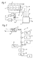
- FIG. 1 shows an air-compressing injection internal combustion engine with an exhaust gas 2 and an intake system 3.
- a throttle element designed as a flap 4 is arranged, which can be actuated via the linkage 33 of a pneumatic actuator 5 and an electropneumatic pressure converter 6 acting on this actuator 5 is.
- the pressure converter 6 is controlled by an electronic control unit 7 which, via the sensor 8 and the measured value line 9, has an absolute pressure p abs, is a signal in the intake system 3 downstream of the throttle valve 4, via the sensor 10 and the measured value line 11 a the intake air temperature T L at this point corresponding signal, via the sensor 12 and the measured value line 13 a signal corresponding to the temperature T KM of the coolant of the internal combustion engine 1 and a signal corresponding to the atmospheric pressure p atm is supplied via the sensor 14 and the measured value line 15.
- the actuation of the throttle valve 4 via the electropneumatic pressure converter 6 and the actuator 5 has the advantage that a very rapid readjustment of the throttle valve 4 is ensured when the control signal output by the electronic control unit 7 via the control line 34 changes. Furthermore, the throttle valve 4 can be controlled very sensitively, so that even a slight change in the control signal causes the throttle valve 4 to respond.
- the throttle valve 4 is actuated according to the block diagram 16 shown in FIG. 2.
- an engine map 17 corresponds to the current internal combustion engine load X RS (X RS is a measure of the deflection of the control rod on the injection pump of the internal combustion engine 1 and thus a measure of the load) and speed n a setpoint for the absolute pressure p abs, is determined.
- X RS is a measure of the deflection of the control rod on the injection pump of the internal combustion engine 1 and thus a measure of the load
- speed n a setpoint for the absolute pressure p abs
- blocks 24-26 are used to additively correct this setpoint p abs, setpoint via block 24 as a function of the atmospheric pressure p Atm detected by sensor 14, via block 25 as a function of the intake air temperature T L detected by sensor 10 and via block 26 as a function of temperature T KM of the coolant for internal combustion engine 1 as determined by sensor 12.
- the correction as a function of the atmospheric pressure p Atm is carried out in accordance with Diagram 27 in FIG. 4a such that the setpoint for the absolute pressure p abs, is to be linearly reduced starting from 760 Torr with falling atmospheric pressure p Atm , in that the amount of the correction value ⁇ p increases.
- the correction ⁇ p of the target value for the absolute pressure p abs should be continuously reduced up to a first intake air temperature value of 20 ° C. with increasing intake air temperature T L , in the middle intake air temperature range from 20 ° C. to one second intake air temperature value of 40 ° C kept constant and continuously increased again from the second intake air temperature value of 40 ° C with increasing intake air temperature T L.
- the graph 29 in FIG. 4c shows the correction ⁇ p of the setpoint value for the absolute pressure p abs read out from the characteristic 17 , intended as a function of the coolant temperature T KM .
- the correction ⁇ p of the setpoint is continuously reduced down to a first coolant temperature value of 80 ° with increasing coolant temperature T KM , from this first cooling mean temperature value up to a second coolant temperature value of 100 ° C kept constant and continuously increased again from this second value with increasing coolant temperature T KM .
- the absolute pressure p abs is now adjusted to this corrected target value p abs, soll, k , and is adjusted in the intake system 3, which is detected by the sensor 8 (block 30), with the aid of a PI controller (block 31). This is done by correspondingly controlling the throttle valve 4 or the electropneumatic pressure converter 6 that actuates it via the pneumatic actuator 5. In this case, the regulator output signal is amplified into an actuating signal for the electropneumatic pressure converter 6 with the aid of an output stage (block 32).
- An increase in the throttling of the intake air flow that is to say a reduction in the flow cross section in the intake system 3, leads to a decrease in the absolute pressure p abs, is downstream of the throttle valve 4 in the intake system 3.
- a corrective increase in the target value for the absolute pressure p abs is intended to be a reduction in the intake air throttling, that is to say an increase in the flow cross section in the intake system 3 and vice versa.
Applications Claiming Priority (2)
| Application Number | Priority Date | Filing Date | Title |
|---|---|---|---|
| DE3932420 | 1989-09-28 | ||
| DE3932420A DE3932420A1 (de) | 1989-09-28 | 1989-09-28 | Verfahren zur betaetigung einer in der abgasleitung einer luftverdichtenden einspritzbrennkraftmaschine angeordneten drosselklappe |
Publications (3)
| Publication Number | Publication Date |
|---|---|
| EP0419808A2 true EP0419808A2 (fr) | 1991-04-03 |
| EP0419808A3 EP0419808A3 (en) | 1991-11-13 |
| EP0419808B1 EP0419808B1 (fr) | 1994-07-06 |
Family
ID=6390409
Family Applications (1)
| Application Number | Title | Priority Date | Filing Date |
|---|---|---|---|
| EP90114654A Expired - Lifetime EP0419808B1 (fr) | 1989-09-28 | 1990-07-31 | Méthode d'actionnement d'une vanne disposée dans l'échappement d'un moteur à combustion à injection et compression d'air |
Country Status (5)
| Country | Link |
|---|---|
| US (1) | US5088462A (fr) |
| EP (1) | EP0419808B1 (fr) |
| JP (1) | JP2519120B2 (fr) |
| AT (1) | ATE108245T1 (fr) |
| DE (1) | DE3932420A1 (fr) |
Cited By (5)
| Publication number | Priority date | Publication date | Assignee | Title |
|---|---|---|---|---|
| EP0450787A2 (fr) * | 1990-04-04 | 1991-10-09 | Lucas Industries Public Limited Company | Système et méthode de commande de moteur |
| FR2677405A1 (fr) * | 1991-06-07 | 1992-12-11 | Daimler Benz Ag | Dispositif de reglage de pression. |
| FR2695165A1 (fr) * | 1992-08-26 | 1994-03-04 | Bosch Gmbh Robert | Procédé et dispositif pour la formation de la valeur de consigne pour une régulation de la pression dans la tubulure d'aspiration et/ou de la pression d'admission d'un moteur à combustion interne. |
| FR2705735A1 (fr) * | 1993-05-24 | 1994-12-02 | Rabhi Vianney | Dispositif de sous-alimentation des moteurs à combustion interne à pistons. |
| FR2982645A1 (fr) * | 2011-11-16 | 2013-05-17 | Peugeot Citroen Automobiles Sa | Commande de fonctionnement d'un moteur a combustion interne de type diesel |
Families Citing this family (10)
| Publication number | Priority date | Publication date | Assignee | Title |
|---|---|---|---|---|
| DE4205266C1 (en) * | 1992-02-21 | 1993-04-01 | Mercedes-Benz Aktiengesellschaft, 7000 Stuttgart, De | Controlling intake line cross=section in fuel injection engine - taking operating parameters into account, reading them from identification field memory, which has been established in tests |
| DE4415650C2 (de) * | 1994-05-04 | 1997-04-03 | Daimler Benz Ag | Verfahren zur Beeinflussung der Zeitdauer bis zum Erreichen der Aktivierungstemperatur einer im Abgasstrang einer luftverdichtenden Einspritzbrennkraftmaschine angeordneten Abgasreinigungsvorrichtung |
| DE19525815B4 (de) * | 1995-07-15 | 2007-05-03 | Robert Bosch Gmbh | Verfahren zur Erfassung des Lastsignals einer Brennkraftmaschine |
| DE19620778C1 (de) * | 1996-05-23 | 1997-08-21 | Daimler Benz Ag | Verfahren zur Regelung des Druckes im Ansaugkanal einer Brennkraftmaschine und Vorrichtung zur Durchführung des Verfahrens |
| JP2000054893A (ja) | 1998-08-04 | 2000-02-22 | Toyota Motor Corp | 内燃機関の吸気絞り弁制御装置 |
| US6367447B1 (en) | 2001-02-21 | 2002-04-09 | Ford Global Technologies, Inc. | Adjustment of driver demand for atmospheric conditions |
| FR2874970B1 (fr) * | 2004-09-06 | 2009-07-03 | Renault Sas | Procede de regeneration d'un systeme de motorisation a filtre a particules |
| JP4257375B2 (ja) * | 2007-01-16 | 2009-04-22 | 本田技研工業株式会社 | 内燃機関の吸気制御装置 |
| WO2016073588A1 (fr) | 2014-11-04 | 2016-05-12 | Cummins Inc. | Systèmes, procédés et appareil pour le fonctionnement de moteurs à deux combustibles |
| CN111120127A (zh) * | 2019-11-12 | 2020-05-08 | 安庆中船柴油机有限公司 | 一种船用减少柴油机冒黑烟系统及其方法 |
Citations (5)
| Publication number | Priority date | Publication date | Assignee | Title |
|---|---|---|---|---|
| JPS5896133A (ja) * | 1981-12-01 | 1983-06-08 | Toyota Motor Corp | デイ−ゼルエンジンの吸気絞り装置 |
| JPS58140431A (ja) * | 1982-02-16 | 1983-08-20 | Toyota Motor Corp | デイ−ゼル機関の吸気絞り制御装置 |
| US4570591A (en) * | 1984-01-13 | 1986-02-18 | Nippon Soken, Inc. | System for controlling throttling of intake air and pressure of fuel injection in diesel engine |
| FR2605049A1 (fr) * | 1986-10-14 | 1988-04-15 | Renault | Dispositif d'admission d'air dans un moteur diesel et procedes de commande de ce dispositif. |
| GB2216596A (en) * | 1988-03-15 | 1989-10-11 | Alexander Robertson | Air intake throttle control for fuel-injection engine |
Family Cites Families (10)
| Publication number | Priority date | Publication date | Assignee | Title |
|---|---|---|---|---|
| JPS56107925A (en) * | 1980-01-31 | 1981-08-27 | Mikuni Kogyo Co Ltd | Electronically controlled fuel injector for ignited internal combustion engine |
| JPS5726252A (en) * | 1980-07-23 | 1982-02-12 | Nissan Motor Co Ltd | Exhaust gas recycling controller of diesel engine |
| US4470396A (en) * | 1982-12-02 | 1984-09-11 | Mikuni Kogyo Kabushiki Kaisha | Internal combustion engine control system with means for reshaping of command from driver's foot pedal |
| US4473052A (en) * | 1983-05-25 | 1984-09-25 | Mikuni Kogyo Kabushiki Kaisha | Full open throttle control for internal combustion engine |
| JPS60135639A (ja) * | 1983-12-23 | 1985-07-19 | Honda Motor Co Ltd | 内燃エンジンの吸入空気量制御方法 |
| USRE33027E (en) * | 1984-06-08 | 1989-08-22 | Mitsubishi Jidosha Kogyo Kabushiki Kaisha | Engine idling speed controlling system |
| JPS627945A (ja) * | 1985-07-04 | 1987-01-14 | Mazda Motor Corp | エンジンの運転領域制御装置 |
| JPH0823330B2 (ja) * | 1986-10-31 | 1996-03-06 | 三菱自動車工業株式会社 | 車両用エンジンの制御装置 |
| US5002028A (en) * | 1988-07-27 | 1991-03-26 | Honda Giken Kogyo Kabushiki Kaisha | Throttle control system for vehicular internal combustion engine |
| DE3840465A1 (de) * | 1988-12-01 | 1990-06-07 | Vdo Schindling | Elektropneumatische verstellvorrichtung fuer eine drosselklappe einer brennkraftmaschine |
-
1989
- 1989-09-28 DE DE3932420A patent/DE3932420A1/de active Granted
-
1990
- 1990-07-31 AT AT90114654T patent/ATE108245T1/de not_active IP Right Cessation
- 1990-07-31 EP EP90114654A patent/EP0419808B1/fr not_active Expired - Lifetime
- 1990-09-25 JP JP2252089A patent/JP2519120B2/ja not_active Expired - Lifetime
- 1990-09-27 US US07/588,711 patent/US5088462A/en not_active Expired - Fee Related
Patent Citations (5)
| Publication number | Priority date | Publication date | Assignee | Title |
|---|---|---|---|---|
| JPS5896133A (ja) * | 1981-12-01 | 1983-06-08 | Toyota Motor Corp | デイ−ゼルエンジンの吸気絞り装置 |
| JPS58140431A (ja) * | 1982-02-16 | 1983-08-20 | Toyota Motor Corp | デイ−ゼル機関の吸気絞り制御装置 |
| US4570591A (en) * | 1984-01-13 | 1986-02-18 | Nippon Soken, Inc. | System for controlling throttling of intake air and pressure of fuel injection in diesel engine |
| FR2605049A1 (fr) * | 1986-10-14 | 1988-04-15 | Renault | Dispositif d'admission d'air dans un moteur diesel et procedes de commande de ce dispositif. |
| GB2216596A (en) * | 1988-03-15 | 1989-10-11 | Alexander Robertson | Air intake throttle control for fuel-injection engine |
Non-Patent Citations (2)
| Title |
|---|
| PATENT ABSTRACTS OF JAPAN, Band 7, Nr. 197 (M-239)[1342], 27. August 1983; & JP-A-58 96 133 (TOYOTA JIDOSHA KOGYO K.K.) 08-06-1983 * |
| PATENT ABSTRACTS OF JAPAN, Band 7, Nr. 257 (M-256)[1402], 16. November 1983; & JP-A-58 140 431 (TOYOTA JIDOSHA KOGYO K.K.) 20-08-1983 * |
Cited By (8)
| Publication number | Priority date | Publication date | Assignee | Title |
|---|---|---|---|---|
| EP0450787A2 (fr) * | 1990-04-04 | 1991-10-09 | Lucas Industries Public Limited Company | Système et méthode de commande de moteur |
| EP0450787A3 (en) * | 1990-04-04 | 1992-09-09 | Lucas Industries Public Limited Company | Engine control system and method |
| US5261236A (en) * | 1990-04-04 | 1993-11-16 | Lucas Industries Public Limited Company | Turbocharged engine control system |
| FR2677405A1 (fr) * | 1991-06-07 | 1992-12-11 | Daimler Benz Ag | Dispositif de reglage de pression. |
| FR2695165A1 (fr) * | 1992-08-26 | 1994-03-04 | Bosch Gmbh Robert | Procédé et dispositif pour la formation de la valeur de consigne pour une régulation de la pression dans la tubulure d'aspiration et/ou de la pression d'admission d'un moteur à combustion interne. |
| FR2705735A1 (fr) * | 1993-05-24 | 1994-12-02 | Rabhi Vianney | Dispositif de sous-alimentation des moteurs à combustion interne à pistons. |
| FR2982645A1 (fr) * | 2011-11-16 | 2013-05-17 | Peugeot Citroen Automobiles Sa | Commande de fonctionnement d'un moteur a combustion interne de type diesel |
| WO2013072590A1 (fr) * | 2011-11-16 | 2013-05-23 | Peugeot Citroen Automobiles Sa | Commande de fonctionnement d'un moteur a combustion interne de type diesel |
Also Published As
| Publication number | Publication date |
|---|---|
| DE3932420A1 (de) | 1991-04-11 |
| EP0419808B1 (fr) | 1994-07-06 |
| DE3932420C2 (fr) | 1993-09-09 |
| ATE108245T1 (de) | 1994-07-15 |
| EP0419808A3 (en) | 1991-11-13 |
| US5088462A (en) | 1992-02-18 |
| JP2519120B2 (ja) | 1996-07-31 |
| JPH03121221A (ja) | 1991-05-23 |
Similar Documents
| Publication | Publication Date | Title |
|---|---|---|
| EP0419808A2 (fr) | Méthode d'actionnement d'une vanne disposée dans l'échappement d'un moteur à combustion à injection et compression d'air | |
| DE19531871C1 (de) | Verfahren zur Regelung des Ladedrucks bei einer mittels eines Abgasturboladers mit verstellbarer Turbinengeometrie aufgeladenen Brennkraftmaschine | |
| EP0084037B2 (fr) | Dispositif de commande de la pression d'alimentation d'un moteur a combustion suralimente | |
| DE2364712C2 (de) | Vorrichtung zur Regelung der Abgasrückführung einer Brennkraftmaschine | |
| DE3444877C2 (fr) | ||
| EP0760056B1 (fr) | Procede et dispositif de commande d'un moteur a combustion interne | |
| EP0810360B1 (fr) | Système de contrôle de moteur à combustion | |
| DE3924582A1 (de) | Drosselklappen-steuersystem zur radschlupfunterdrueckung bei kraftfahrzeug-brennkraftmaschinen | |
| DE2650246A1 (de) | Steuereinrichtung fuer eine kraftstoffeinspritzpumpe eines dieselmotors | |
| DE4330368A1 (de) | Verfahren und Vorrichtung zur Steuerung der Antriebsleistung eines Fahrzeugs | |
| DE4404668A1 (de) | Verfahren und Vorrichtung zur Steuerung der Leistung einer Brennkraftmaschine | |
| EP0077997B1 (fr) | Procédé et dispositif de réglage de la vitesse d'un moteur à combustion | |
| DE102009055236A1 (de) | Verfahren und Vorrichtung zur Regelung eines Abgasturboladers | |
| DE3306484A1 (de) | Abgas-steuervorrichtung fuer brennkraftmaschinen mit turbolader und katalytischem konverter zur abgasentgiftung | |
| EP3594480B1 (fr) | Procédé de commande d'un système de charge | |
| DE3939754A1 (de) | Verfahren zur regelung des druckes in der ansaugleitung vor den einlassventilen bei einer mittels eines abgasturboladers aufgeladenen luftverdichtenden einspritzbrennkraftmaschine | |
| DE19612739A1 (de) | Abgasrückführungs-Steuerungsanlage | |
| DE4015293A1 (de) | System zur regelung eines betriebsparameters einer brennkraftmaschine eines kraftfahrzeugs | |
| DE4224893B4 (de) | Verfahren zur Kraftstoffzumessung für eine Brennkraftmaschine in Verbindung mit einem Heißstart | |
| DE19746213C2 (de) | Verfahren und Vorrichtung zur Abgasrückführungssteuerung bei Brennkraftmaschinen | |
| DE3022999A1 (de) | Einrichtung zur drehzahlabhaengigen schliessbegrenzung einer vergaser-hauptdrossel | |
| EP0797730A1 (fr) | Procede de commande du dosage de carburant dans des moteurs a combustion interne | |
| EP0728922B1 (fr) | Régulation de débit de masse d'air avec constante d'intégration adaptée pour moteur à combustion interne turbocompressée | |
| DE10144670C1 (de) | Verfahren zur Steuerung des Drucks in einer Unterdruckkammer eines Unterdruck-Bremskraftverstärkers | |
| DE3727669C1 (en) | Method for controlling a supercharged, air-compressing internal combustion engine with fuel injection |
Legal Events
| Date | Code | Title | Description |
|---|---|---|---|
| PUAI | Public reference made under article 153(3) epc to a published international application that has entered the european phase |
Free format text: ORIGINAL CODE: 0009012 |
|
| AK | Designated contracting states |
Kind code of ref document: A2 Designated state(s): AT CH FR IT LI SE |
|
| PUAL | Search report despatched |
Free format text: ORIGINAL CODE: 0009013 |
|
| AK | Designated contracting states |
Kind code of ref document: A3 Designated state(s): AT CH FR IT LI SE |
|
| 17P | Request for examination filed |
Effective date: 19911009 |
|
| 17Q | First examination report despatched |
Effective date: 19930430 |
|
| ITF | It: translation for a ep patent filed |
Owner name: BARZANO' E ZANARDO ROMA S.P.A. |
|
| GRAA | (expected) grant |
Free format text: ORIGINAL CODE: 0009210 |
|
| RAP1 | Party data changed (applicant data changed or rights of an application transferred) |
Owner name: MERCEDES-BENZ AG |
|
| AK | Designated contracting states |
Kind code of ref document: B1 Designated state(s): AT CH FR IT LI SE |
|
| REF | Corresponds to: |
Ref document number: 108245 Country of ref document: AT Date of ref document: 19940715 Kind code of ref document: T |
|
| ET | Fr: translation filed | ||
| EAL | Se: european patent in force in sweden |
Ref document number: 90114654.8 |
|
| PLBE | No opposition filed within time limit |
Free format text: ORIGINAL CODE: 0009261 |
|
| STAA | Information on the status of an ep patent application or granted ep patent |
Free format text: STATUS: NO OPPOSITION FILED WITHIN TIME LIMIT |
|
| 26N | No opposition filed | ||
| ITTA | It: last paid annual fee | ||
| REG | Reference to a national code |
Ref country code: CH Ref legal event code: PFA Free format text: MERCEDES-BENZ AKTIENGESELLSCHAFT TRANSFER- DAIMLER-BENZ AKTIENGESELLSCHAFT |
|
| REG | Reference to a national code |
Ref country code: FR Ref legal event code: TP |
|
| PGFP | Annual fee paid to national office [announced via postgrant information from national office to epo] |
Ref country code: AT Payment date: 19990719 Year of fee payment: 10 |
|
| PGFP | Annual fee paid to national office [announced via postgrant information from national office to epo] |
Ref country code: SE Payment date: 19990721 Year of fee payment: 10 |
|
| PGFP | Annual fee paid to national office [announced via postgrant information from national office to epo] |
Ref country code: FR Payment date: 19990722 Year of fee payment: 10 Ref country code: CH Payment date: 19990722 Year of fee payment: 10 |
|
| REG | Reference to a national code |
Ref country code: CH Ref legal event code: PFA Free format text: DAIMLER-BENZ AKTIENGESELLSCHAFT TRANSFER- DAIMLERCHRYSLER AG |
|
| PG25 | Lapsed in a contracting state [announced via postgrant information from national office to epo] |
Ref country code: LI Free format text: LAPSE BECAUSE OF NON-PAYMENT OF DUE FEES Effective date: 20000731 Ref country code: CH Free format text: LAPSE BECAUSE OF NON-PAYMENT OF DUE FEES Effective date: 20000731 Ref country code: AT Free format text: LAPSE BECAUSE OF NON-PAYMENT OF DUE FEES Effective date: 20000731 |
|
| PG25 | Lapsed in a contracting state [announced via postgrant information from national office to epo] |
Ref country code: SE Free format text: LAPSE BECAUSE OF NON-PAYMENT OF DUE FEES Effective date: 20000801 |
|
| REG | Reference to a national code |
Ref country code: CH Ref legal event code: PL |
|
| PG25 | Lapsed in a contracting state [announced via postgrant information from national office to epo] |
Ref country code: FR Free format text: LAPSE BECAUSE OF NON-PAYMENT OF DUE FEES Effective date: 20010330 |
|
| EUG | Se: european patent has lapsed |
Ref document number: 90114654.8 |
|
| REG | Reference to a national code |
Ref country code: FR Ref legal event code: ST |
|
| PG25 | Lapsed in a contracting state [announced via postgrant information from national office to epo] |
Ref country code: IT Free format text: LAPSE BECAUSE OF NON-PAYMENT OF DUE FEES;WARNING: LAPSES OF ITALIAN PATENTS WITH EFFECTIVE DATE BEFORE 2007 MAY HAVE OCCURRED AT ANY TIME BEFORE 2007. THE CORRECT EFFECTIVE DATE MAY BE DIFFERENT FROM THE ONE RECORDED. Effective date: 20050731 |