EP0419808A2 - Method for driving a throttle in the exhaust pipe of an injected air compressing combustion engine - Google Patents
Method for driving a throttle in the exhaust pipe of an injected air compressing combustion engine Download PDFInfo
- Publication number
- EP0419808A2 EP0419808A2 EP90114654A EP90114654A EP0419808A2 EP 0419808 A2 EP0419808 A2 EP 0419808A2 EP 90114654 A EP90114654 A EP 90114654A EP 90114654 A EP90114654 A EP 90114654A EP 0419808 A2 EP0419808 A2 EP 0419808A2
- Authority
- EP
- European Patent Office
- Prior art keywords
- intake air
- absolute pressure
- abs
- value
- throttle element
- Prior art date
- Legal status (The legal status is an assumption and is not a legal conclusion. Google has not performed a legal analysis and makes no representation as to the accuracy of the status listed.)
- Granted
Links
Images

Classifications
-
- F—MECHANICAL ENGINEERING; LIGHTING; HEATING; WEAPONS; BLASTING
- F02—COMBUSTION ENGINES; HOT-GAS OR COMBUSTION-PRODUCT ENGINE PLANTS
- F02D—CONTROLLING COMBUSTION ENGINES
- F02D41/00—Electrical control of supply of combustible mixture or its constituents
- F02D41/0002—Controlling intake air
-
- F—MECHANICAL ENGINEERING; LIGHTING; HEATING; WEAPONS; BLASTING
- F02—COMBUSTION ENGINES; HOT-GAS OR COMBUSTION-PRODUCT ENGINE PLANTS
- F02D—CONTROLLING COMBUSTION ENGINES
- F02D9/00—Controlling engines by throttling air or fuel-and-air induction conduits or exhaust conduits
- F02D9/02—Controlling engines by throttling air or fuel-and-air induction conduits or exhaust conduits concerning induction conduits
-
- F—MECHANICAL ENGINEERING; LIGHTING; HEATING; WEAPONS; BLASTING
- F02—COMBUSTION ENGINES; HOT-GAS OR COMBUSTION-PRODUCT ENGINE PLANTS
- F02B—INTERNAL-COMBUSTION PISTON ENGINES; COMBUSTION ENGINES IN GENERAL
- F02B3/00—Engines characterised by air compression and subsequent fuel addition
- F02B3/06—Engines characterised by air compression and subsequent fuel addition with compression ignition
-
- F—MECHANICAL ENGINEERING; LIGHTING; HEATING; WEAPONS; BLASTING
- F02—COMBUSTION ENGINES; HOT-GAS OR COMBUSTION-PRODUCT ENGINE PLANTS
- F02D—CONTROLLING COMBUSTION ENGINES
- F02D9/00—Controlling engines by throttling air or fuel-and-air induction conduits or exhaust conduits
- F02D9/02—Controlling engines by throttling air or fuel-and-air induction conduits or exhaust conduits concerning induction conduits
- F02D2009/0201—Arrangements; Control features; Details thereof
- F02D2009/0223—Cooling water temperature
-
- F—MECHANICAL ENGINEERING; LIGHTING; HEATING; WEAPONS; BLASTING
- F02—COMBUSTION ENGINES; HOT-GAS OR COMBUSTION-PRODUCT ENGINE PLANTS
- F02D—CONTROLLING COMBUSTION ENGINES
- F02D9/00—Controlling engines by throttling air or fuel-and-air induction conduits or exhaust conduits
- F02D9/02—Controlling engines by throttling air or fuel-and-air induction conduits or exhaust conduits concerning induction conduits
- F02D2009/0201—Arrangements; Control features; Details thereof
- F02D2009/0225—Intake air or mixture temperature
-
- F—MECHANICAL ENGINEERING; LIGHTING; HEATING; WEAPONS; BLASTING
- F02—COMBUSTION ENGINES; HOT-GAS OR COMBUSTION-PRODUCT ENGINE PLANTS
- F02D—CONTROLLING COMBUSTION ENGINES
- F02D9/00—Controlling engines by throttling air or fuel-and-air induction conduits or exhaust conduits
- F02D9/02—Controlling engines by throttling air or fuel-and-air induction conduits or exhaust conduits concerning induction conduits
- F02D2009/0201—Arrangements; Control features; Details thereof
- F02D2009/0227—Atmospheric pressure
-
- F—MECHANICAL ENGINEERING; LIGHTING; HEATING; WEAPONS; BLASTING
- F02—COMBUSTION ENGINES; HOT-GAS OR COMBUSTION-PRODUCT ENGINE PLANTS
- F02D—CONTROLLING COMBUSTION ENGINES
- F02D9/00—Controlling engines by throttling air or fuel-and-air induction conduits or exhaust conduits
- F02D9/02—Controlling engines by throttling air or fuel-and-air induction conduits or exhaust conduits concerning induction conduits
- F02D2009/0201—Arrangements; Control features; Details thereof
- F02D2009/0228—Manifold pressure
-
- F—MECHANICAL ENGINEERING; LIGHTING; HEATING; WEAPONS; BLASTING
- F02—COMBUSTION ENGINES; HOT-GAS OR COMBUSTION-PRODUCT ENGINE PLANTS
- F02D—CONTROLLING COMBUSTION ENGINES
- F02D9/00—Controlling engines by throttling air or fuel-and-air induction conduits or exhaust conduits
- F02D9/02—Controlling engines by throttling air or fuel-and-air induction conduits or exhaust conduits concerning induction conduits
- F02D2009/0201—Arrangements; Control features; Details thereof
- F02D2009/023—Engine speed
-
- F—MECHANICAL ENGINEERING; LIGHTING; HEATING; WEAPONS; BLASTING
- F02—COMBUSTION ENGINES; HOT-GAS OR COMBUSTION-PRODUCT ENGINE PLANTS
- F02D—CONTROLLING COMBUSTION ENGINES
- F02D9/00—Controlling engines by throttling air or fuel-and-air induction conduits or exhaust conduits
- F02D9/02—Controlling engines by throttling air or fuel-and-air induction conduits or exhaust conduits concerning induction conduits
- F02D2009/0201—Arrangements; Control features; Details thereof
- F02D2009/0238—Increasing ignition delay
-
- F—MECHANICAL ENGINEERING; LIGHTING; HEATING; WEAPONS; BLASTING
- F02—COMBUSTION ENGINES; HOT-GAS OR COMBUSTION-PRODUCT ENGINE PLANTS
- F02D—CONTROLLING COMBUSTION ENGINES
- F02D41/00—Electrical control of supply of combustible mixture or its constituents
- F02D41/0002—Controlling intake air
- F02D2041/0022—Controlling intake air for diesel engines by throttle control
-
- Y—GENERAL TAGGING OF NEW TECHNOLOGICAL DEVELOPMENTS; GENERAL TAGGING OF CROSS-SECTIONAL TECHNOLOGIES SPANNING OVER SEVERAL SECTIONS OF THE IPC; TECHNICAL SUBJECTS COVERED BY FORMER USPC CROSS-REFERENCE ART COLLECTIONS [XRACs] AND DIGESTS
- Y02—TECHNOLOGIES OR APPLICATIONS FOR MITIGATION OR ADAPTATION AGAINST CLIMATE CHANGE
- Y02T—CLIMATE CHANGE MITIGATION TECHNOLOGIES RELATED TO TRANSPORTATION
- Y02T10/00—Road transport of goods or passengers
- Y02T10/10—Internal combustion engine [ICE] based vehicles
- Y02T10/40—Engine management systems
Definitions
- the invention relates to a method for actuating a throttle element arranged in the exhaust line of an air-compressing injection internal combustion engine according to the preamble of patent claim 1.
- DE-PS 31 28 783 uses such a method for controlling the exhaust gas recirculation to reduce pollutant emissions, in particular particle emissions. Furthermore, the exhaust gas recirculation can reduce nitrogen oxide (NO x ) emissions.
- the throttle valve arranged in the suction line is actuated in stages in coordination with an exhaust gas recirculation valve arranged in an exhaust gas recirculation line.
- the invention has for its object to provide a method of the type specified in the preamble of claim 1, with which a reduction in pollutant emissions, in particular particle and nitrogen oxide emissions can be achieved without the use of a complex device for exhaust gas recirculation.
- the correction of the target value for the absolute pressure in the intake system according to claim 4 always ensures the same or only a partially reduced differential pressure between the intake system and the atmosphere in relation to a specific load and speed point.
- the throttling effect is thus independent of the height at which the internal combustion engine is currently being operated, although a complete opening of the throttle valve below a predetermined limit value for the atmospheric pressure, that is to say from a certain height, prevents premature "blue smoking" of the internal combustion engine.
- Claims 7 and 8 show a device for carrying out the method according to the invention and an advantageous embodiment thereof.
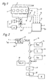
- FIG. 1 shows an air-compressing injection internal combustion engine with an exhaust gas 2 and an intake system 3.
- a throttle element designed as a flap 4 is arranged, which can be actuated via the linkage 33 of a pneumatic actuator 5 and an electropneumatic pressure converter 6 acting on this actuator 5 is.
- the pressure converter 6 is controlled by an electronic control unit 7 which, via the sensor 8 and the measured value line 9, has an absolute pressure p abs, is a signal in the intake system 3 downstream of the throttle valve 4, via the sensor 10 and the measured value line 11 a the intake air temperature T L at this point corresponding signal, via the sensor 12 and the measured value line 13 a signal corresponding to the temperature T KM of the coolant of the internal combustion engine 1 and a signal corresponding to the atmospheric pressure p atm is supplied via the sensor 14 and the measured value line 15.
- the actuation of the throttle valve 4 via the electropneumatic pressure converter 6 and the actuator 5 has the advantage that a very rapid readjustment of the throttle valve 4 is ensured when the control signal output by the electronic control unit 7 via the control line 34 changes. Furthermore, the throttle valve 4 can be controlled very sensitively, so that even a slight change in the control signal causes the throttle valve 4 to respond.
- the throttle valve 4 is actuated according to the block diagram 16 shown in FIG. 2.
- an engine map 17 corresponds to the current internal combustion engine load X RS (X RS is a measure of the deflection of the control rod on the injection pump of the internal combustion engine 1 and thus a measure of the load) and speed n a setpoint for the absolute pressure p abs, is determined.
- X RS is a measure of the deflection of the control rod on the injection pump of the internal combustion engine 1 and thus a measure of the load
- speed n a setpoint for the absolute pressure p abs
- blocks 24-26 are used to additively correct this setpoint p abs, setpoint via block 24 as a function of the atmospheric pressure p Atm detected by sensor 14, via block 25 as a function of the intake air temperature T L detected by sensor 10 and via block 26 as a function of temperature T KM of the coolant for internal combustion engine 1 as determined by sensor 12.
- the correction as a function of the atmospheric pressure p Atm is carried out in accordance with Diagram 27 in FIG. 4a such that the setpoint for the absolute pressure p abs, is to be linearly reduced starting from 760 Torr with falling atmospheric pressure p Atm , in that the amount of the correction value ⁇ p increases.
- the correction ⁇ p of the target value for the absolute pressure p abs should be continuously reduced up to a first intake air temperature value of 20 ° C. with increasing intake air temperature T L , in the middle intake air temperature range from 20 ° C. to one second intake air temperature value of 40 ° C kept constant and continuously increased again from the second intake air temperature value of 40 ° C with increasing intake air temperature T L.
- the graph 29 in FIG. 4c shows the correction ⁇ p of the setpoint value for the absolute pressure p abs read out from the characteristic 17 , intended as a function of the coolant temperature T KM .
- the correction ⁇ p of the setpoint is continuously reduced down to a first coolant temperature value of 80 ° with increasing coolant temperature T KM , from this first cooling mean temperature value up to a second coolant temperature value of 100 ° C kept constant and continuously increased again from this second value with increasing coolant temperature T KM .
- the absolute pressure p abs is now adjusted to this corrected target value p abs, soll, k , and is adjusted in the intake system 3, which is detected by the sensor 8 (block 30), with the aid of a PI controller (block 31). This is done by correspondingly controlling the throttle valve 4 or the electropneumatic pressure converter 6 that actuates it via the pneumatic actuator 5. In this case, the regulator output signal is amplified into an actuating signal for the electropneumatic pressure converter 6 with the aid of an output stage (block 32).
- An increase in the throttling of the intake air flow that is to say a reduction in the flow cross section in the intake system 3, leads to a decrease in the absolute pressure p abs, is downstream of the throttle valve 4 in the intake system 3.
- a corrective increase in the target value for the absolute pressure p abs is intended to be a reduction in the intake air throttling, that is to say an increase in the flow cross section in the intake system 3 and vice versa.
Abstract
Description
Die Erfindung bezieht sich auf ein Verfahren zur Betätigung eines in der Abgasleitung einer luftverdichtenden Einspritzbrennkraftmaschine angeordneten Drosselelementes gemäß Oberbegriff des Patentanspruches 1.The invention relates to a method for actuating a throttle element arranged in the exhaust line of an air-compressing injection internal combustion engine according to the preamble of patent claim 1.
Aus der DE-PS 31 28 783 wird ein derartiges Verfahren zur Steuerung der Abgasrückführung zur Reduzierung der Schadstoffemission, insbesondere der Partikelemission eingesetzt. Ferner ist durch die Abgasrückführung eine Reduzierung des Stickoxid (NOx)-Ausstoßes zur erreichen. Die Betätigung der in der Saugleitung angeordneten Drosselklappe erfolgt dabei stufenweise in Abstimmung mit einem in einer Abgasrückführleitung angeordneten Abgasrückführventil.DE-PS 31 28 783 uses such a method for controlling the exhaust gas recirculation to reduce pollutant emissions, in particular particle emissions. Furthermore, the exhaust gas recirculation can reduce nitrogen oxide (NO x ) emissions. The throttle valve arranged in the suction line is actuated in stages in coordination with an exhaust gas recirculation valve arranged in an exhaust gas recirculation line.
Der Erfindung liegt die Aufgabe zugrunde, ein Verfahren der im Oberbegriff des Patentanspruches 1 angegebenen Art aufzuzeigen, mit welchem eine Reduzierung der Schadstoffemission, insbesondere der Partikel- und Stickoxidemission ohne den Einsatz einer aufwendigen Einrichtung zur Abgasrückführung erreichbar ist.The invention has for its object to provide a method of the type specified in the preamble of claim 1, with which a reduction in pollutant emissions, in particular particle and nitrogen oxide emissions can be achieved without the use of a complex device for exhaust gas recirculation.
Die Aufgabe wird erfindungsgemäß durch die Merkmale des kennzeichnenden Teiles des Hauptanspruches gelost.The object is achieved by the features of the characterizing part of the main claim.
Durch eine Reduzierung des Ansaugluftmassenstromes durch Drosselung des Ansaugluftstromes wird bis in den Teillastbereich aufgrund einer verringerten Auskühlung des Brennraumes generell eine verbesserte Verbrennung und damit eine reduzierte Schadstoffemission erzielt. Darüber hinaus wird durch die erfindungsgemaße sehr feinfühlige Abstimmung der Ansaugluftdrosselung auf den jeweiligen Betriebspunkt der Brennkraftmaschine zum einen eine gezielte Reduzierung der Reaktionspartner Stickstoff und Sauerstoff und zum anderen eine gezielte Erhöhung des Zündverzuges bewirkt. Dies führt zu einer relativ spätlastigen Wärmefreisetzung im Brennraum, welche zu einer nur verminderten Partikel- und Stickoxidbildung führt, wobei jedoch gleichzeitig nur eine unwesentliche Beeinflussung der Kohlenwasserstoffemission gegeben ist. Dieser Heizverlauf führt zudem zu einer verstärkten Oxidation der zu Beginn des Verbrennungsvorganges entstehenden Partikel und damit auch zu einer Reduzierung der Partikelemission.By reducing the intake air mass flow by throttling the intake air flow, improved combustion and thus reduced pollutant emissions are generally achieved down to the partial load range due to reduced cooling of the combustion chamber. In addition, the very sensitive adjustment of the intake air throttling to the respective operating point of the internal combustion engine results in a targeted reduction of the reactants nitrogen and oxygen on the one hand and a targeted increase in the ignition delay on the other. This leads to a relatively late load heat release in the combustion chamber, which leads to only a reduced formation of particles and nitrogen oxide, but at the same time there is only an insignificant influence on the hydrocarbon emission. This heating process also leads to increased oxidation of the particles formed at the start of the combustion process and thus to a reduction in particle emissions.
Die Korrektur des Sollwertes für den Absolutdruck im Ansaugsystem gemäß Anspruch 4 gewährleistet bezogen auf einen bestimmten Last- und Drehzahlpunkt immer den gleichen oder einen nur teilweise verminderten Differenzdruck zwischen dem Ansaugsystem und der Atmosphäre. Die Drosselwirkung wird damit unabhängig von der Höhe, in welcher die Brennkraftmaschine gerade betrieben wird, wobei jedoch ein vollstandiges Öffnen der Drosselklappe unterhalb eines vorgegebenen Grenzwertes für den Atmospharendruck, also ab einer bestimmten Höhe, ein vorzeitiges "Blaurauchen" der Brennkraftmaschine verhindert.
Mit der Ausgestaltung des Verfahrens nach Anspruch 5 wird durch eine Reduzierung der Drosselung (Erhöhung des Sollwertes für den Absolutdruck) in Richtung niederer Außentemperaturen die Blaurauchempfindlichkeit vermindert und gleichzeitig in Richtung höherer Außentemperaturen ebenfalls durch eine Reduzierung der Drosselung eine thermische Überlastung der Brennkraftmaschine verhindert. Analog gilt für die Ausgestaltung nach Anspruch 6, daß in der Kaltlaufphase der Brennkraftmaschine die Blaurauchempfindlichkeit reduziert ist und ebenso die Brennkraftmaschine vor einer thermischen Überlastung geschützt ist.The correction of the target value for the absolute pressure in the intake system according to claim 4 always ensures the same or only a partially reduced differential pressure between the intake system and the atmosphere in relation to a specific load and speed point. The throttling effect is thus independent of the height at which the internal combustion engine is currently being operated, although a complete opening of the throttle valve below a predetermined limit value for the atmospheric pressure, that is to say from a certain height, prevents premature "blue smoking" of the internal combustion engine.
With the design of the method according to
Mit den Anspruchen 7 und 8 ist eine Vorrichtung zur Durchführung des erfindungsgemäßen Verfahrens und eine vorteilhafte Ausgestaltungsform hierzu aufgezeigt.
In der Zeichnung ist das erfindungsgemäße Verfahren anhand eines Ausführungsbeispieles aufgezeigt. Im einzelnen zeigt
- Figur 1 ein Ausführungsbeispiel einer Vorrichtung zur Durchführung des erfindungsgemäßen Verfahrens in einer Prinzipdarstellung,
Figur 2 die erfindungsgemäße Ansteuerung der Drosselklappe in einem Blockschaltbild,Figur 3 ein Kennfeld für eine Brennkraftmaschine n = f(XRS),- Figur 4a-c 3 Diagramme, gemäß derer der Sollwert für den Absolutdruck pabs,soll korrigiert wird.
- FIG. 1 shows an exemplary embodiment of a device for carrying out the method according to the invention in a basic illustration,
- FIG. 2 shows the control of the throttle valve according to the invention in a block diagram,
- FIG. 3 shows a characteristic diagram for an internal combustion engine n = f (X RS ),
- Figure 4a-
c 3 diagrams, according to which the target value for the absolute pressure p abs is to be corrected.
In Figur 1 zeigt 1 eine luftverdichtende Einspritzbrennkraftmaschine mit einem Abgas 2- und einem Ansaugsystem 3. In dem Ansaugsystem 3 ist ein als Klappe 4 ausgebildetes Drosselelement angeordnet, welches über das Gestänge 33 eines pneumatischen Stellgliedes 5 und einen dieses Stellglied 5 beaufschlagenden elektropneumatischen Druckumsetzer 6 betatigbar ist. Angesteuert wird der Druckumsetzer 6 von einer elektronischen Steuereinheit 7, welcher über den Sensor 8 und die Meßwertleitung 9 ein dem Absolutdruck pabs,ist im Ansaugsystem 3 stromab der Drosselklappe 4 entsprechendes Signal, über den Sensor 10 und die Meßwertleitung 11 ein der Ansauglufttemperatur TL an dieser Stelle entsprechendes Signal, über den Sensor 12 und die Meßwertleitung 13 ein der Temperatur TKM des Kühlmittels der Brennkraftmaschine 1 entsprechendes Signal und über den Sensor 14 und die Meßwertleitung 15 ein dem Atmosphärendruck pAtm entsprechendes Signal zugeführt wird. Die Betätigung der Drosselklappe 4 über den elektropneumatischen Druckumsetzer 6 und das Stellglied 5 hat den Vorteil, daß bei einer Änderung des von der elektronischen Steuereinheit 7 über die Steuerleitung 34 ausgegebenen Steuersignals ein sehr schnelles Nachstellen der Drosselklappe 4 gewährleistet ist. Ferner ist die Drosselklappe 4 sehr feinfühlig steuerbar, so daß schon eine geringe Änderung des Steuersignals ein Ansprechen der Drosselklappe 4 verursacht.1 shows an air-compressing injection internal combustion engine with an
Die Ansteuerung der Drosselklappe 4 erfolgt gemäß dem in der Figur 2 dargestellten Blockdiagramm 16. Zunächst wird in Block 18 aus einem Motorenkennfeld 17 (s. auch Figur 3) entsprechend der gerade aktuellen Brennkraftmaschinenlast XRS (XRS ist ein Maß für die Auslenkung der Regelstange an der Einspritzpumpe der Brennkraftmaschine 1 und damit ein Maß für die Last) und Drehzahl n ein Sollwert für den Absolutdruck pabs,soll ermittelt. In dem Kennfeld 17 in Figur 3 bezeichnen 19 die Kennlinien für den Drosselbereich, wobei entlang dieser Linien 19 ein konstanter Absolutdruck pabs,soll gegeben ist. Ab der gestrichelten Linie 20 bis hin zur Vollastkennlinie 21 (schraffierter Bereich) erfolgt keine Drosselung der Ansaugluft mehr. In Richtung des Pfeiles 22 nimmt der Absolutdruck pabs,soll zu. Der Bereich maximaler Drosselung liegt also in dem Bereich 23. Das Kennfeld 17 ist ausgelegt auf einen Umgebungs- bzw. Atmosphärendruck pAtm von 760 Torr (Meereshöhe).The throttle valve 4 is actuated according to the block diagram 16 shown in FIG. 2. First, in
Nach der Ermittlung des Sollwertes für den Absolutdruck pabs,soll erfolgt über die Blöcke 24 - 26 (Figur 2) eine additive Korrektur dieses Sollwertes pabs,soll und zwar über den Block 24 in Abhängigkeit des über den Sensor 14 erfaßten Atmospharendruckes pAtm, über den Block 25 in Abhängigkeit der über den Sensor 10 erfaßten Ansauglufttemperatur TL und über den Block 26 in Abhängigkeit der über den Sensor 12 erfaßten Temperatur TKM des Kühlmittels für die Brennkraftmaschine 1. Die Korrektur in Abhängigkeit des Atmosphärendruckes pAtm erfolgt dabei gemäß dem Schaubild 27 in Figur 4a derart, daß der Sollwert für den Absolutdruck pabs,soll mit fallendem Atmosphärendruck pAtm ausgehend von 760 Torr linear reduziert wird, indem der Betrag des Korrekturwertes Δ p zunimmt. Wird z.B. beim Befahren einer Steigung in dem gerade aktuellen Betriebszustand der Brennkraftmaschine (Last, Drehzahl) aus dem Kennfeld 17 ein Sollwert für den Absolutdruck pabs,soll von 700 Torr ausgelesen, so gilt dieser Sollwert zunächst einmal nur für den Atmospharendruck auf Meereshöhe. Da sich nun der Atmosphärendruck pAtm mit steigender Höhe kontinuierlich verringert, ist ab derjenigen Höhe, ab der die 700 Torr Absolutdruck im Ansaugsystem 3 durch den Zugewinn an Höhe automatisch erreicht sind, die Drosselklappe 4 vollständig geöffnet, obwohl im Hinblick auf die Schadstoffemission eine gewisse Drosselung der Ansaugluft noch möglich wäre. Dem wird nun erfindungsgemäß dadurch Rechnung getragen, daß von dem ausgelesenen Sollwert von 700 Torr entsprechend dem aktuellen Atmosphärendruck pAtm noch ein vorgegebener Korrekturwert Δ p abgezogen wird (Addition eines negativen Δ p), so daß der Absolutdruck im Ansaugsystem 3 durch ein entsprechendes Anstellen der Drosselklappe 4 auf einen niedereren Wert eingeregelt wird. Unterhalb eines vorgegebenen Grenzwertes von 630 Torr schließlich wird die Drosselklappe 4 in ihre den gesamten Querschnitt des Ansaugsystems 3 freigebende Stellung (gestrichelte Darstellung der Drosselklappe 4) überführt.After the setpoint value for the absolute pressure p abs has been determined, blocks 24-26 (FIG. 2) are used to additively correct this setpoint p abs, setpoint via
Gemäß Schaubild 28 der Figur 4b wird die Korrektur Δ p des Sollwertes für den Absolutdruck pabs,soll bis hin zu einem ersten Ansauglufttemperaturwert von 20°C mit steigender Ansauglufttemperatur TL kontinuierlich verringert, in dem mittleren Ansauglufttemperaturbereich von 20°C bis hin zu einem zweiten Ansauglufttemperaturwert von 40°C konstant gehalten und ab dem zweiten Ansauglufttemperaturwert von 40°C mit steigender Ansauglufttemperatur TL wieder kontinuierlich erhöht.According to diagram 28 in FIG. 4b, the correction Δp of the target value for the absolute pressure p abs, should be continuously reduced up to a first intake air temperature value of 20 ° C. with increasing intake air temperature T L , in the middle intake air temperature range from 20 ° C. to one second intake air temperature value of 40 ° C kept constant and continuously increased again from the second intake air temperature value of 40 ° C with increasing intake air temperature T L.
Das Schaubild 29 in Figur 4c schließlich zeigt die Korrektur Δ p des aus dem Kennfald 17 ausgelesenen Sollwertes für den Absolutdruck pabs,soll in Abhangigkeit der Kühlmitteltemperatur TKM. Die Korrektur Δ p des Sollwertes wird dabei bis hin zu einem ersten Kühlmitteltemperaturwert von 80° mit steigender Kühlmitteltemperatur TKM kontinuierlich verringert, von diesem ersten Kühl mitteltemperaturwert bis hin zu einem zweiten Kuhlmitteltemperaturwert von 100°C konstant gehalten und ab diesem zweiten Wert mit steigender Kühlmitteltemperatur TKM wieder kontinuierlich vergrößert.Finally, the
Auf diesen korrigierten Sollwert pabs,soll,k wird nun der Absolutdruck pabs,ist im Ansaugsystem 3, welcher über den Sensor 8 erfaßt wird (Block 30), mit Hilfe eines PI-Reglers nachgeregelt (Block 31). Dies geschieht durch eine entsprechende Ansteuerung der Drosselklappe 4 bzw. des diese über das pneumatische Stellglied 5 betätigenden elektropneumatischen Druckumsetzers 6. Hierbei wird mit Hilfe einer Endstufe das Regelerausgangssignal zu einem Stellsignal für den elektropneumatischen Druckumsetzer 6 verstärkt (Block 32).The absolute pressure p abs is now adjusted to this corrected target value p abs, soll, k , and is adjusted in the
Eine Erhöhung der Drosselung des Ansaugluftstromes, also eine Verringerung des Strömungsquerschnittes im Ansaugsystem 3 bewirkt eine Verringerung des Absolutdruckes pabs,ist im Ansaugsystem 3 stromab der Drosselklappe 4. Damit ist für die Steuerung bzw. für die Regelung der Drosselklappenstellung generell zu sagen, daß - bezogen auf einen festen Betriebspunkt der Brennkraftmaschine 1 - eine korrektive Erhöhung des Sollwertes für den Absolutdruck pabs,soll einer Reduzierung der Ansaugluftdrosselung, also einer Vergrößerung des Strömungsquerschnittes im Ansaugsystem 3 gleichkommt und umgekehrt.An increase in the throttling of the intake air flow, that is to say a reduction in the flow cross section in the
Claims (7)
dadurch gekennzeichnet,
daß das Drosselelement (4) in jedem Betriebspunkt der Brennkraftmaschine (1) auf diejenige Öffnungsstellung eingeregelt wird, welche einem aus einem last- und drehzahlabhängigen Kennfeld (17) ermittelten Sollwert für den Absolutdruck (pabs,soll) im Ansaugsystem (3) stromab des Drosselelementes (4) entspricht, wobei der Sollwert für den Absolutdruck (pabs,soll) in Abhängigkeit des Atmosphärendruckes (pAtm) derart korriegiert wird, daß der Betrag der Korrektur (Δ p) des Sollwertes für den Absolutdruck (pabs,soll) mit fallendem Atmosphärendruck (pAtm) linear erhöht wird und daß unterhalb eines vorgegebenen Grenzwertes für den Atmospharendruck (pAtm) das Drosselelement (4) in seine den gesamten Querschnitt des Ansaugsystems freigebende Stellung überführt wird.1.Method for actuating a throttle element arranged in the intake system of an air-compressing injection internal combustion engine, which is held in the closed position in low load and speed ranges and in an open position in medium and high load and speed ranges, with each operating point of the internal combustion engine having a specific open position which can be determined from a map is assigned to the throttle element,
characterized,
that the throttle element (4) is adjusted at each operating point of the internal combustion engine (1) to that opening position which is determined from a load and speed-dependent map (17) setpoint for the absolute pressure (p abs, set ) in the intake system (3) downstream of the Throttle element (4) corresponds, the target value for the absolute pressure (p abs, target) being corrected as a function of the atmospheric pressure (p Atm ) such that the amount of correction (Δ p) of the target value for the absolute pressure (p abs, target) is linearly increased with falling atmospheric pressure (p atm ) and that below a predetermined limit value for atmospheric pressure (p atm ) the throttle element (4) is transferred into its position which releases the entire cross section of the intake system.
dadurch gekennzeichnet,
daß die Korrektur des Sollwertes für den Absolutdruck (pabs,soll) additiv erfolgt.2. The method according to claim 1,
characterized,
that the correction of the setpoint for the absolute pressure (p abs, set ) is carried out additively.
dadurch gekennzeichnet,
daß die Korrektur des Sollwertes für den Absolutdruck (pabs,soll) in Abhängigkeit der Ansauglufttemperatur (TL) und/oder der Kühlmitteltemperatur (TKM) erfolgt.3. The method according to any one of claims 1 to 2,
characterized,
that the correction of the target value for the absolute pressure (p abs, soll ) takes place depending on the intake air temperature (T L ) and / or the coolant temperature (T KM ).
dadurch gekennzeichnet,
daß die Korrektur (Δ p) des Sollwertes für den Absolutdruck (pabs,soll) im niederen Ansauglufttemperaturbereich bis hin zu einem ersten Ansauglufttemperaturwert mit steigender Ansauglufttemperatur (TL) reduziert wird, ab diesem ersten Ansauglufttemperaturwert bis hin zu einem zweiten Ansauglufttemperaturwert konstant gehalten wird und ab diesem zweiten Ansauglufttemperaturwert mit steigender Ansauglufttemperatur (TL) wieder erhöht wird, wobei der zweite Ansauglufttemperaturwert größer ist als der erste.4. The method according to claim 3,
characterized,
that the correction (Δ p) of the setpoint for the absolute pressure (p abs, soll ) is reduced in the lower intake air temperature range up to a first intake air temperature value with increasing intake air temperature (T L ), is kept constant from this first intake air temperature value up to a second intake air temperature value and from this second intake air temperature value is increased again with increasing intake air temperature (T L ), the second intake air temperature value being greater than the first.
dadurch gekennzeichnet,
daß die Korrektur (Δ p) des Sollwertes für den Absolutdruck (pabs,soll) bis hin zu einer ersten Kühlmitteltemperatur mit steigender Kühlmitteltemperatur (TKM) verringert wird, ausgehend von diesem ersten Kühlmitteltemperaturwert bis hin zu einem zweiten Kühlmitteltemperaturwert konstant gehalten wird und ab diesem zweiten Kühlmitteltemperaturwert mit steigender Kühlmitteltemperatur (TKM) wieder erhöht wird, wobei der zweite Kühlmitteltemperaturwert größer ist als der erste.5. The method according to any one of claims 3 to 4,
characterized,
that the correction (Δ p) of the target value for the absolute pressure (p abs, soll ) is reduced to a first coolant temperature with increasing coolant temperature (T KM ), is kept constant starting from this first coolant temperature value up to a second coolant temperature value and from this second coolant temperature value is increased again with increasing coolant temperature (T KM ), the second coolant temperature value being greater than the first.
dadurch gekennzeichnet,
daß ein den Atmosphärendruck (pAtm) erfassender Sensor (14) vorgesehen ist, welcher über eine weitere Meßwertleitung (15) mit der elektronischen Steuereinheit (7) verbunden ist.6. Device for performing the method according to one of claims 1 to 5 with an actuator for actuating the throttle element (4), which is controlled by an electronic control unit, which in turn is one of the current engine speed, one of the current engine load, one of the current coolant temperature and a measured value signal corresponding to the absolute pressure downstream of the throttle element is supplied,
characterized,
that a sensor (14) detecting the atmospheric pressure (p atm ) is provided, which is connected to the electronic control unit (7) via a further measured value line (15).
dadurch gekennzeichnet,
daß das Drosselelement (4) klappenförmig ausgebildet ist und daß der Stellantrieb zur Betätigung der Drosselklappe (4) gebildet ist durch einen von der elektronischen Steuereinheit (7) ansteuerbaren elektropneumatischen Druckumsetzer (6), welcher ein mit der Drosselklappe (4) über ein Gestänge (33) verbundenes pneumatisches Stellglied (5) beaufschlagt.7. The device according to claim 6,
characterized,
that the throttle element (4) is flap-shaped and that the actuator for actuating the throttle valve (4) is formed by an electropneumatic pressure converter (6) which can be controlled by the electronic control unit (7) and which is connected to the throttle valve (4) via a linkage ( 33) connected pneumatic actuator (5).
Applications Claiming Priority (2)
| Application Number | Priority Date | Filing Date | Title |
|---|---|---|---|
| DE3932420 | 1989-09-28 | ||
| DE3932420A DE3932420A1 (en) | 1989-09-28 | 1989-09-28 | METHOD FOR ACTUATING A THROTTLE VALVE ARRANGED IN THE EXHAUST PIPE OF AN AIR COMPRESSING INTERNAL COMBUSTION ENGINE |
Publications (3)
| Publication Number | Publication Date |
|---|---|
| EP0419808A2 true EP0419808A2 (en) | 1991-04-03 |
| EP0419808A3 EP0419808A3 (en) | 1991-11-13 |
| EP0419808B1 EP0419808B1 (en) | 1994-07-06 |
Family
ID=6390409
Family Applications (1)
| Application Number | Title | Priority Date | Filing Date |
|---|---|---|---|
| EP90114654A Expired - Lifetime EP0419808B1 (en) | 1989-09-28 | 1990-07-31 | Method for driving a throttle in the exhaust pipe of an injected air compressing combustion engine |
Country Status (5)
| Country | Link |
|---|---|
| US (1) | US5088462A (en) |
| EP (1) | EP0419808B1 (en) |
| JP (1) | JP2519120B2 (en) |
| AT (1) | ATE108245T1 (en) |
| DE (1) | DE3932420A1 (en) |
Cited By (5)
| Publication number | Priority date | Publication date | Assignee | Title |
|---|---|---|---|---|
| EP0450787A2 (en) * | 1990-04-04 | 1991-10-09 | Lucas Industries Public Limited Company | Engine control system and method |
| FR2677405A1 (en) * | 1991-06-07 | 1992-12-11 | Daimler Benz Ag | PRESSURE ADJUSTING DEVICE. |
| FR2695165A1 (en) * | 1992-08-26 | 1994-03-04 | Bosch Gmbh Robert | Method and device for the formation of the set point for regulating the pressure in the suction pipe and / or the inlet pressure of an internal combustion engine. |
| FR2705735A1 (en) * | 1993-05-24 | 1994-12-02 | Rabhi Vianney | Device for underfuelling piston-type internal combustion engines |
| FR2982645A1 (en) * | 2011-11-16 | 2013-05-17 | Peugeot Citroen Automobiles Sa | OPERATING CONTROL OF A DIESEL TYPE INTERNAL COMBUSTION ENGINE |
Families Citing this family (10)
| Publication number | Priority date | Publication date | Assignee | Title |
|---|---|---|---|---|
| DE4205266C1 (en) * | 1992-02-21 | 1993-04-01 | Mercedes-Benz Aktiengesellschaft, 7000 Stuttgart, De | Controlling intake line cross=section in fuel injection engine - taking operating parameters into account, reading them from identification field memory, which has been established in tests |
| DE4415650C2 (en) * | 1994-05-04 | 1997-04-03 | Daimler Benz Ag | Method for influencing the period of time until the activation temperature of an exhaust gas cleaning device arranged in the exhaust line of an air-compressing injection internal combustion engine is reached |
| DE19525815B4 (en) * | 1995-07-15 | 2007-05-03 | Robert Bosch Gmbh | Method for detecting the load signal of an internal combustion engine |
| DE19620778C1 (en) * | 1996-05-23 | 1997-08-21 | Daimler Benz Ag | Method of pressure control for intake port of vehicle IC engine operating with turbocharger |
| JP2000054893A (en) | 1998-08-04 | 2000-02-22 | Toyota Motor Corp | Intake throttle valve control device for internal combustion engine |
| US6367447B1 (en) | 2001-02-21 | 2002-04-09 | Ford Global Technologies, Inc. | Adjustment of driver demand for atmospheric conditions |
| FR2874970B1 (en) * | 2004-09-06 | 2009-07-03 | Renault Sas | METHOD FOR REGENERATING A PARTICLE FILTER MOTORIZATION SYSTEM |
| JP4257375B2 (en) * | 2007-01-16 | 2009-04-22 | 本田技研工業株式会社 | Intake control device for internal combustion engine |
| WO2016073588A1 (en) | 2014-11-04 | 2016-05-12 | Cummins Inc. | Systems, methods, and apparatus for operation of dual fuel engines |
| CN111120127A (en) * | 2019-11-12 | 2020-05-08 | 安庆中船柴油机有限公司 | Marine system and method for reducing black smoke emitted by diesel engine |
Citations (5)
| Publication number | Priority date | Publication date | Assignee | Title |
|---|---|---|---|---|
| JPS5896133A (en) * | 1981-12-01 | 1983-06-08 | Toyota Motor Corp | Intake air throttle device of diesel engine |
| JPS58140431A (en) * | 1982-02-16 | 1983-08-20 | Toyota Motor Corp | Controller for choking of suction air for diesel engine |
| US4570591A (en) * | 1984-01-13 | 1986-02-18 | Nippon Soken, Inc. | System for controlling throttling of intake air and pressure of fuel injection in diesel engine |
| FR2605049A1 (en) * | 1986-10-14 | 1988-04-15 | Renault | Device for taking air into a diesel engine, and methods for controlling this device |
| GB2216596A (en) * | 1988-03-15 | 1989-10-11 | Alexander Robertson | Air intake throttle control for fuel-injection engine |
Family Cites Families (10)
| Publication number | Priority date | Publication date | Assignee | Title |
|---|---|---|---|---|
| JPS56107925A (en) * | 1980-01-31 | 1981-08-27 | Mikuni Kogyo Co Ltd | Electronically controlled fuel injector for ignited internal combustion engine |
| JPS5726252A (en) * | 1980-07-23 | 1982-02-12 | Nissan Motor Co Ltd | Exhaust gas recycling controller of diesel engine |
| US4470396A (en) * | 1982-12-02 | 1984-09-11 | Mikuni Kogyo Kabushiki Kaisha | Internal combustion engine control system with means for reshaping of command from driver's foot pedal |
| US4473052A (en) * | 1983-05-25 | 1984-09-25 | Mikuni Kogyo Kabushiki Kaisha | Full open throttle control for internal combustion engine |
| JPS60135639A (en) * | 1983-12-23 | 1985-07-19 | Honda Motor Co Ltd | Method of controlling quantity of intake air supplied to internal-combustion engine |
| USRE33027E (en) * | 1984-06-08 | 1989-08-22 | Mitsubishi Jidosha Kogyo Kabushiki Kaisha | Engine idling speed controlling system |
| JPS627945A (en) * | 1985-07-04 | 1987-01-14 | Mazda Motor Corp | Operation region control device for engine |
| JPH0823330B2 (en) * | 1986-10-31 | 1996-03-06 | 三菱自動車工業株式会社 | Vehicle engine controller |
| US5002028A (en) * | 1988-07-27 | 1991-03-26 | Honda Giken Kogyo Kabushiki Kaisha | Throttle control system for vehicular internal combustion engine |
| DE3840465A1 (en) * | 1988-12-01 | 1990-06-07 | Vdo Schindling | ELECTROPNEUMATIC ADJUSTING DEVICE FOR A THROTTLE VALVE OF AN INTERNAL COMBUSTION ENGINE |
-
1989
- 1989-09-28 DE DE3932420A patent/DE3932420A1/en active Granted
-
1990
- 1990-07-31 EP EP90114654A patent/EP0419808B1/en not_active Expired - Lifetime
- 1990-07-31 AT AT90114654T patent/ATE108245T1/en not_active IP Right Cessation
- 1990-09-25 JP JP2252089A patent/JP2519120B2/en not_active Expired - Lifetime
- 1990-09-27 US US07/588,711 patent/US5088462A/en not_active Expired - Fee Related
Patent Citations (5)
| Publication number | Priority date | Publication date | Assignee | Title |
|---|---|---|---|---|
| JPS5896133A (en) * | 1981-12-01 | 1983-06-08 | Toyota Motor Corp | Intake air throttle device of diesel engine |
| JPS58140431A (en) * | 1982-02-16 | 1983-08-20 | Toyota Motor Corp | Controller for choking of suction air for diesel engine |
| US4570591A (en) * | 1984-01-13 | 1986-02-18 | Nippon Soken, Inc. | System for controlling throttling of intake air and pressure of fuel injection in diesel engine |
| FR2605049A1 (en) * | 1986-10-14 | 1988-04-15 | Renault | Device for taking air into a diesel engine, and methods for controlling this device |
| GB2216596A (en) * | 1988-03-15 | 1989-10-11 | Alexander Robertson | Air intake throttle control for fuel-injection engine |
Non-Patent Citations (2)
| Title |
|---|
| PATENT ABSTRACTS OF JAPAN, Band 7, Nr. 197 (M-239)[1342], 27. August 1983; & JP-A-58 96 133 (TOYOTA JIDOSHA KOGYO K.K.) 08-06-1983 * |
| PATENT ABSTRACTS OF JAPAN, Band 7, Nr. 257 (M-256)[1402], 16. November 1983; & JP-A-58 140 431 (TOYOTA JIDOSHA KOGYO K.K.) 20-08-1983 * |
Cited By (8)
| Publication number | Priority date | Publication date | Assignee | Title |
|---|---|---|---|---|
| EP0450787A2 (en) * | 1990-04-04 | 1991-10-09 | Lucas Industries Public Limited Company | Engine control system and method |
| EP0450787A3 (en) * | 1990-04-04 | 1992-09-09 | Lucas Industries Public Limited Company | Engine control system and method |
| US5261236A (en) * | 1990-04-04 | 1993-11-16 | Lucas Industries Public Limited Company | Turbocharged engine control system |
| FR2677405A1 (en) * | 1991-06-07 | 1992-12-11 | Daimler Benz Ag | PRESSURE ADJUSTING DEVICE. |
| FR2695165A1 (en) * | 1992-08-26 | 1994-03-04 | Bosch Gmbh Robert | Method and device for the formation of the set point for regulating the pressure in the suction pipe and / or the inlet pressure of an internal combustion engine. |
| FR2705735A1 (en) * | 1993-05-24 | 1994-12-02 | Rabhi Vianney | Device for underfuelling piston-type internal combustion engines |
| FR2982645A1 (en) * | 2011-11-16 | 2013-05-17 | Peugeot Citroen Automobiles Sa | OPERATING CONTROL OF A DIESEL TYPE INTERNAL COMBUSTION ENGINE |
| WO2013072590A1 (en) * | 2011-11-16 | 2013-05-23 | Peugeot Citroen Automobiles Sa | Controlling the operation of a diesel internal combustion engine |
Also Published As
| Publication number | Publication date |
|---|---|
| US5088462A (en) | 1992-02-18 |
| ATE108245T1 (en) | 1994-07-15 |
| EP0419808A3 (en) | 1991-11-13 |
| JPH03121221A (en) | 1991-05-23 |
| DE3932420C2 (en) | 1993-09-09 |
| DE3932420A1 (en) | 1991-04-11 |
| JP2519120B2 (en) | 1996-07-31 |
| EP0419808B1 (en) | 1994-07-06 |
Similar Documents
| Publication | Publication Date | Title |
|---|---|---|
| EP0419808A2 (en) | Method for driving a throttle in the exhaust pipe of an injected air compressing combustion engine | |
| DE19531871C1 (en) | Air pressure control system for turbocharged engine | |
| EP0084037B2 (en) | Control device for the supply pressure of a supercharged combustion engine | |
| DE2364712C2 (en) | Device for regulating the exhaust gas recirculation of an internal combustion engine | |
| DE3444877C2 (en) | ||
| EP0810360B1 (en) | System for controlling a combustion engine | |
| DE3924582A1 (en) | THROTTLE VALVE CONTROL SYSTEM FOR WHEEL SLIP REPRESSION IN MOTOR VEHICLE INTERNAL COMBUSTION ENGINES | |
| DE2650246A1 (en) | CONTROL DEVICE FOR A FUEL INJECTION PUMP OF A DIESEL ENGINE | |
| DE4404668A1 (en) | Control of vehicle catalyser IC engine output | |
| DE4330368A1 (en) | Method and device for controlling the drive power output of a vehicle | |
| EP0077997B1 (en) | Process and apparatus for controlling the rotational speed of a combustion engine | |
| DE102009055236A1 (en) | Method for regulating exhaust-gas turbocharger of internal combustion engine, involves detecting operating parameter of internal combustion engine on basis of set rotation speed of exhaust-gas turbocharger | |
| DE3306484A1 (en) | Exhaust-gas control system for internal combustion engines with a turbocharger and a catalytic converter for exhaust-gas detoxification | |
| EP3594480B1 (en) | Method for controlling a charging system | |
| DE19612739A1 (en) | Exhaust gas recirculation control system | |
| DE4015293A1 (en) | SYSTEM FOR CONTROLLING AN OPERATING PARAMETER OF AN INTERNAL COMBUSTION ENGINE OF A MOTOR VEHICLE | |
| DE4224893B4 (en) | Method for fuel metering for an internal combustion engine in conjunction with a hot start | |
| DE19746213C2 (en) | Method and device for exhaust gas recirculation control in internal combustion engines | |
| DE3022999A1 (en) | DEVICE FOR SPEED-dependent LOCKING LIMITATION OF A CARBURETOR MAIN THROTTLE | |
| EP0797730A1 (en) | Fuel dosage control process for internal combustion engines | |
| EP0728922B1 (en) | Controller with adapted integral part for the air mass flow of a turbocharged internal combustion engine | |
| DE10144670C1 (en) | Method for controlling the pressure in a vacuum chamber of a vacuum brake booster | |
| DE3727669C1 (en) | Method for controlling a supercharged, air-compressing internal combustion engine with fuel injection | |
| EP0381858B1 (en) | Device for controlling the intake mixture temperature of an internal-combustion engine, particularly in motor vehicles | |
| DE3601784C2 (en) |
Legal Events
| Date | Code | Title | Description |
|---|---|---|---|
| PUAI | Public reference made under article 153(3) epc to a published international application that has entered the european phase |
Free format text: ORIGINAL CODE: 0009012 |
|
| AK | Designated contracting states |
Kind code of ref document: A2 Designated state(s): AT CH FR IT LI SE |
|
| PUAL | Search report despatched |
Free format text: ORIGINAL CODE: 0009013 |
|
| AK | Designated contracting states |
Kind code of ref document: A3 Designated state(s): AT CH FR IT LI SE |
|
| 17P | Request for examination filed |
Effective date: 19911009 |
|
| 17Q | First examination report despatched |
Effective date: 19930430 |
|
| ITF | It: translation for a ep patent filed |
Owner name: BARZANO' E ZANARDO ROMA S.P.A. |
|
| GRAA | (expected) grant |
Free format text: ORIGINAL CODE: 0009210 |
|
| RAP1 | Party data changed (applicant data changed or rights of an application transferred) |
Owner name: MERCEDES-BENZ AG |
|
| AK | Designated contracting states |
Kind code of ref document: B1 Designated state(s): AT CH FR IT LI SE |
|
| REF | Corresponds to: |
Ref document number: 108245 Country of ref document: AT Date of ref document: 19940715 Kind code of ref document: T |
|
| ET | Fr: translation filed | ||
| EAL | Se: european patent in force in sweden |
Ref document number: 90114654.8 |
|
| PLBE | No opposition filed within time limit |
Free format text: ORIGINAL CODE: 0009261 |
|
| STAA | Information on the status of an ep patent application or granted ep patent |
Free format text: STATUS: NO OPPOSITION FILED WITHIN TIME LIMIT |
|
| 26N | No opposition filed | ||
| ITTA | It: last paid annual fee | ||
| REG | Reference to a national code |
Ref country code: CH Ref legal event code: PFA Free format text: MERCEDES-BENZ AKTIENGESELLSCHAFT TRANSFER- DAIMLER-BENZ AKTIENGESELLSCHAFT |
|
| REG | Reference to a national code |
Ref country code: FR Ref legal event code: TP |
|
| PGFP | Annual fee paid to national office [announced via postgrant information from national office to epo] |
Ref country code: AT Payment date: 19990719 Year of fee payment: 10 |
|
| PGFP | Annual fee paid to national office [announced via postgrant information from national office to epo] |
Ref country code: SE Payment date: 19990721 Year of fee payment: 10 |
|
| PGFP | Annual fee paid to national office [announced via postgrant information from national office to epo] |
Ref country code: FR Payment date: 19990722 Year of fee payment: 10 Ref country code: CH Payment date: 19990722 Year of fee payment: 10 |
|
| REG | Reference to a national code |
Ref country code: CH Ref legal event code: PFA Free format text: DAIMLER-BENZ AKTIENGESELLSCHAFT TRANSFER- DAIMLERCHRYSLER AG |
|
| PG25 | Lapsed in a contracting state [announced via postgrant information from national office to epo] |
Ref country code: LI Free format text: LAPSE BECAUSE OF NON-PAYMENT OF DUE FEES Effective date: 20000731 Ref country code: CH Free format text: LAPSE BECAUSE OF NON-PAYMENT OF DUE FEES Effective date: 20000731 Ref country code: AT Free format text: LAPSE BECAUSE OF NON-PAYMENT OF DUE FEES Effective date: 20000731 |
|
| PG25 | Lapsed in a contracting state [announced via postgrant information from national office to epo] |
Ref country code: SE Free format text: LAPSE BECAUSE OF NON-PAYMENT OF DUE FEES Effective date: 20000801 |
|
| REG | Reference to a national code |
Ref country code: CH Ref legal event code: PL |
|
| PG25 | Lapsed in a contracting state [announced via postgrant information from national office to epo] |
Ref country code: FR Free format text: LAPSE BECAUSE OF NON-PAYMENT OF DUE FEES Effective date: 20010330 |
|
| EUG | Se: european patent has lapsed |
Ref document number: 90114654.8 |
|
| REG | Reference to a national code |
Ref country code: FR Ref legal event code: ST |
|
| PG25 | Lapsed in a contracting state [announced via postgrant information from national office to epo] |
Ref country code: IT Free format text: LAPSE BECAUSE OF NON-PAYMENT OF DUE FEES;WARNING: LAPSES OF ITALIAN PATENTS WITH EFFECTIVE DATE BEFORE 2007 MAY HAVE OCCURRED AT ANY TIME BEFORE 2007. THE CORRECT EFFECTIVE DATE MAY BE DIFFERENT FROM THE ONE RECORDED. Effective date: 20050731 |