EP0410084B1 - Transportsystem - Google Patents
Transportsystem Download PDFInfo
- Publication number
- EP0410084B1 EP0410084B1 EP90108540A EP90108540A EP0410084B1 EP 0410084 B1 EP0410084 B1 EP 0410084B1 EP 90108540 A EP90108540 A EP 90108540A EP 90108540 A EP90108540 A EP 90108540A EP 0410084 B1 EP0410084 B1 EP 0410084B1
- Authority
- EP
- European Patent Office
- Prior art keywords
- guide rail
- conveyor
- monorail
- conveying system
- type conveying
- Prior art date
- Legal status (The legal status is an assumption and is not a legal conclusion. Google has not performed a legal analysis and makes no representation as to the accuracy of the status listed.)
- Expired - Lifetime
Links
Images


Classifications
-
- B—PERFORMING OPERATIONS; TRANSPORTING
- B61—RAILWAYS
- B61C—LOCOMOTIVES; MOTOR RAILCARS
- B61C13/00—Locomotives or motor railcars characterised by their application to special systems or purposes
- B61C13/04—Locomotives or motor railcars characterised by their application to special systems or purposes for elevated railways with rigid rails
-
- B—PERFORMING OPERATIONS; TRANSPORTING
- B61—RAILWAYS
- B61B—RAILWAY SYSTEMS; EQUIPMENT THEREFOR NOT OTHERWISE PROVIDED FOR
- B61B13/00—Other railway systems
- B61B13/04—Monorail systems
Definitions
- This invention relates to a freight system and more particularly to an improved article conveying system of the monorail type.
- a monorail system is known from DE-A-33 23 416, comprising a single guide rail and a combined drive and supporting mechanism.
- An electric motor is provided for driving said conveyor along the guide rail.
- the electric motor is positioned with its center of gravity between the sides of the guide rail and beneath the guide rail.
- a first feature of this invention is adapted to be embodied in a monorail type of conveyor including a guide rail.
- the conveyor includes a travelling conveyor that is supported for movement along the guide rail.
- the travelling conveyor is powered by an electrical motor that is positioned so that its center of gravity is disposed substantially in line with the guide rail to increase stability.
- the electrical motor is positioned above the guide rail.
- the travelling conveyor means carries a gripping means that is movable through selected vertical distances relative to the travelling conveyor means so as to accommodate the handling of work pieces at stations that are positioned at various heights relative to the guide rail means.
- Figure 1 is a perspective view showing a plant incorporating a conveyor system constructed similar to the invention.
- Figure 2 is an enlarged end elevational view of the conveyor mechanism, with a portion broken away and shown in section.
- Figure 3 is a side elevational view thereof.
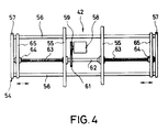
- Figure 4 is a top plan view of the work piece gripping unit.
- Figure 5 is an end elevational view, in part similar to Figure 3 and shows the specific features of the invention.
- a plant such as an automotive engine assembly line, having a conveyor system and which is adapted to deliver work pieces to a delivery conveyor 11 that is positioned in a raised area 12 of the plant and from parts bins 13 positioned at a lower level 14 in the plant.
- the device may pick up work pieces at a higher area and lower them to a lower work area or may move them between various areas depending upon the particular orientation of the plant. Empty work piece buckets are delivered to a transfer conveyor 15.
- the conveyor system includes a mono- or guide rail, indicated generally by the reference numeral 16 and having a construction as will be described.
- the monorail 16 has an ascending portion 17 running to the raised area 12 from the floor 14 and an descending section 18 running in the opposite direction.
- a plurality of conveyor assemblies 19 are supported along the rail 16 for conveying the work pieces in the desired path and making stops at the appropriate stations.
- the conveyor mechanisms 19 will be described in most detail by reference to the remaining figures and first particularly to the embodiment shown in Figures 2 through 4.
- the monorail 16 is comprised primarily of an I beam 21 having a generally vertically extending web and horizontally extending flanges.
- the I beam 21 is supported by means of a plurality of L shaped brackets 22 from a roof 23.
- the configuration of the guide rail assembly 16 is such that the I beam 21 will have raised and lowered areas and also curved areas.
- the embodiment can be utilized in conjunction with conveyors wherein the rail is all positioned at the same elevation, but the invention has particular utility in conjunction with arrangements wherein the rail has elevating and lowering sections.
- the conveyor 19 includes a supporting and driving conveyor, indicated generally by the reference numeral 24 that is comprised of a frame having an upper portion 25 that journals a driving shaft 26 in an appropriate member.
- the driving shaft 26 is driven in a manner to be described and is adapted to be drivingly coupled by means of an electrically operated clutch 27 to a or other high friction material tired drive wheel 28 that is engaged with the upper surface of the upper flange of the I beam 21. Obviously, as the wheel 28 is rotated, the conveyor 19 will traverse along the path defined by the I beam 21.
- a lower frame assembly 31 is suspended from the upper frame assembly 25 by means eluding at least one L shaped bracket 32.
- the frame 31 supports a driving motor 33, the center of gravity of which is vertically beneath the I beam 21 for stability.
- the motor 33 is a high torque, low speed direct driven motor that drives an output shaft 34 on which a drive pulley 35 is supported.
- a belt 36 transfers drive from the shaft 34 to the shaft 26.
- a driven pulley 37 is affixed to the shaft 26.
- the electrically operated clutch 27 drivingly couples the shaft 26 to the drive roller 28 when it is desired to move the conveyor along the rail 21.
- a pair of lower guide rollers 38 that are engaged with opposite sides of the lower flanges of the I beam 21 so as to aid in further stability.
- An idler roller 39 and a pair of spring biased rollers 41 are also engaged with the underside of this lower flange so as to provide the desired degree of engagement of the roller 28 with the upper flange and so as to improve tracking and stability.
- a gripping unit, indicated generally by the reference numeral 42 is suspended from the frame assembly 31 and is movable vertically relative to it by means of a combined drive and suspension unit, indicated generally by the reference numeral 43.
- the unit 43 includes a main driving shaft 44 that is driven from the motor shaft 34 by means of a belt 45.
- An electric clutch 46 is interposed between a pulley 47 that is directly driven by the belt 45 and the shaft 44 so as to selectively actuate the shaft 44 and raise and lower the gripping unit 42 through substantial height variations in the manner now to be described.
- a pair of gears 48 are affixed to the opposite ends of the shaft 44 and are each enmeshed with a pair of diametrically opposed driven gears 51.
- the gears 51 are affixed to shafts upon which drums 52 are fixed.
- the drums 52 have wound on them respective lengths of cable 53 that are connected to a frame assembly 54 of the work piece gripping unit 42.
- the frame assembly 54 includes a pair of cross bars 55 that are connected to perpendicularly extending plates 56 which are capped at their opposite ends by end plates 57.
- An electric motor 58 is carried by the frame assembly 54 and drives a driving gear 59.
- the driving gear 59 is enmeshed with a driven gear 61 that is fixed to a feed shaft 62.
- the feed shaft 62 is journaled on the frame assembly by the plates 55 and 57 and has a pair of threaded portions 63 of opposite hand.
- the threaded portions 63 are received in feed nuts 64 that are affixed to gripping plates 65.
- Operation of the motor 58 which is a reversible motor, will cause the gripping plates 65 to move toward or away from each other between a spaced position as shown in the figures and a gripping position wherein a work piece may be gripped therebetween.
- An electrically operated brake 66 is associated with the drive wheel 28 and selectively locks the conveyor 19 in position on the guide rail 21 at times as will he described.
- an electric brake 67 is associated with the shaft 44 for locking this shaft and the gripping mechanism 55 in its vertically disposed positions.
- Electric power for the motors 33 and 58 the electrically operated clutches 27 and 46 and the electrically operated brakes 66 and 67 are provided by a plurality of power rails 68 that are positioned along the web of the I beam 22 and are engaged by wipers 69 carried by the frame assembly 25. These wipers 69 deliver the power to a power box 71 which, in turn, is connected to a control box 72 so as to control the various electrical components.
- position indicators 73 that are carried by angle brackets 74 and which cooperate with a sensor 75 so as to provide signals to the control device 72 when the conveyor 19 is at certain positions on the guide rail 17, such as at the stations 11, 13 and 15.
- the control mechanism 72 may include a preprogrammed control that will provide the desired sequence of operations, a typical one of which will be hereinafter described. It should be understood, however, that those skilled in the art can readily adapt the control sequences to specific applications.
- the clutches 27 and 46 When the conveyor 19 is at a station indicated by the position indicator 73, normally the clutches 27 and 46 will be disengaged and the brakes 66 and 67 engage. If it is desired to raise or lower the work piece, the brake 67 is released and the clutch 46 is engaged while the brake 66 remains engaged. The gripping device 54 may then be raised or lowered to the appropriate position and the motor 58 energized so as to either grip or release a work piece.
- the gripping device 42 may be again raised or lowered as desired and then the clutch 46 is released and the brake 67 is engaged so as to lock the gripping device 42 at the desired height.
- the brake 66 is released and the clutch 27 is engaged so that the conveyor can move to the next station as determined by the position indicator 73 and sensor 75.
- the gripping device 42 may be raised or lowered and either grip or release a work piece. It is believed from this description that those skilled in the art will readily understand how the conveyor mechanism described can be utilized for any of a wide variety of purposes and in a wide variety of applications.
- an obstruction indicator 76 that is carried by the frame 25 of the conveyor and which will sense of an obstacle is positioned in front of the conveyor 19 and this will effect operation of the brakes 66 and 67 and release of the clutches 27 and 46 until the obstacle has been cleared.
- Figure 5 shows the specific embodiment of the invention which is generally similar to the embodiment of Figures 1 through 4.
- the main drive motor for driving the conveyor 19 along the rail 21 is supported above the rail rather than below it.
- the center of gravity of the drive motor is located vertically within the area of the rail 21 for stability.
- the drive motor 101 is supported on the upper frame 25 and has its output shaft 102 coupled to the shaft 26 by means of a drive belt 103.
- this embodiment is the same as the previously described embodiment and, for that reason, components which are the same as those of the previously described embodiment have been identified by the same reference numerals and further description of them is believed to be unnecessary to understand the construction and operation of this embodiment.
- the described conveyor mechanism permits the use of a monorail assembly with great stability due to the positioning of the drive motor so that is center of gravity is positioned vertically within the outer periphery of the guide rail.
- the way in which the gripper mechanism is supported from the conveying mechanism is particularly useful in accommodating a wide variety of height differences and differences in the point at which work pieces can be picked up an released.
Landscapes
- Engineering & Computer Science (AREA)
- Transportation (AREA)
- Mechanical Engineering (AREA)
- Carriers, Traveling Bodies, And Overhead Traveling Cranes (AREA)
Claims (6)
- Einschienen-Fördersystem, mit einer einzelnen Führungsschiene (16), einem kombinierten Antriebs- und Stützmechanismus (24), der von der Führungsschiene (16) getragen wird, und einer Elektromotoreinrichtung (101) zum Antreiben des Förderers (19) entlang der Führungsschiene (16), wobei der Elektromotor (101) mit seinem Schwerezentrum aus Stabilitätsgründen vertikal zwischen den Seiten der Führungsschiene (16) positioniert ist,
dadurch gekennzeichnet, daß
der Elektromotor (101) oberhalb der Führungsschiene (16) positioniert ist. - Einschienen-Fördersystem nach Anspruch 1, wobei die Fördereinrichtung (19) ein reibschlüssiges Antriebsrad (28) umfaßt, das mit der Oberseite der Einschiene im Eingriff befindlich ist und ein Paar von Spurrollen (29) umfaßt, die mit der Seite der Führungsschiene (16) im Eingriff befindlich sind.
- Einschienen-Fördersystem nach Anspruch 2, wobei die Führungsschiene (16) einen Doppel-T-Träger (21) umfaßt, und wobei die Führungs- und Spurrollen (29) mit den Seiten des Flansches des Doppel-T-Trägers (21) im Eingriff befindlich sind.
- Einschienen-Fördersystem nach Anspruch 3, wobei ein Paar der Führungs- und Spurrollen (29; 38) vorhanden sind, wobei ein Paar dem oberen Flansch des Doppel-T-Trägers (21) zugeordnet ist und das andere Paar dem unteren Flansch des Doppel-T-Trägers (21) zugeordnet ist.
- Einschienen-Fördersystem nach einem der Ansprüche 1 bis 4, das außerdem eine Greifeinrichtung (42) aufweist, die durch den kombinierten Antriebs- und Stützmechanismus (24) getragen wird, und die vertikal dazu beweglich ist, wobei die Greifeinrichtung (42) eine Einrichtung (65) zum Spannen und Lösen eines Werkstückes umfaßt.
- Einschienen-Fördersystem nach Anspruch 5, wobei die Greifeinrichtung (42) mittels flexibler Kabel (53) für eine Bewegung relativ zu der kombinierten Antriebs- und Stützeinrichtung (24) getragen wird.
Applications Claiming Priority (2)
| Application Number | Priority Date | Filing Date | Title |
|---|---|---|---|
| US07/385,576 US5016543A (en) | 1989-07-26 | 1989-07-26 | Freight system |
| US385576 | 2003-03-10 |
Publications (2)
| Publication Number | Publication Date |
|---|---|
| EP0410084A1 EP0410084A1 (de) | 1991-01-30 |
| EP0410084B1 true EP0410084B1 (de) | 1994-04-06 |
Family
ID=23521988
Family Applications (1)
| Application Number | Title | Priority Date | Filing Date |
|---|---|---|---|
| EP90108540A Expired - Lifetime EP0410084B1 (de) | 1989-07-26 | 1990-05-07 | Transportsystem |
Country Status (3)
| Country | Link |
|---|---|
| US (1) | US5016543A (de) |
| EP (1) | EP0410084B1 (de) |
| DE (1) | DE69007890T2 (de) |
Families Citing this family (4)
| Publication number | Priority date | Publication date | Assignee | Title |
|---|---|---|---|---|
| JPH04101763U (ja) * | 1991-02-12 | 1992-09-02 | 株式会社椿本チエイン | 吊下搬送装置のハンガー傾動機構 |
| DE102010041894A1 (de) * | 2010-10-01 | 2012-04-05 | Dürr Systems GmbH | Antriebseinheit für eine Fördervorrichtung |
| DE102016210031A1 (de) * | 2016-06-07 | 2017-12-07 | Schmid Technology Systems Gmbh | Schienenfahrzeug für ein Schienentransportsystem und Schienentransportsystem |
| AT525853A1 (de) * | 2022-02-04 | 2023-08-15 | Tgw Mechanics Gmbh | Verbesserte Hängefördervorrichtung für ein Kommissioniersystem und Transportträger zum Transport von Hängeware |
Family Cites Families (16)
| Publication number | Priority date | Publication date | Assignee | Title |
|---|---|---|---|---|
| US875864A (en) * | 1907-06-27 | 1908-01-07 | John F Stout | Mail-delivery system. |
| US1340962A (en) * | 1919-09-25 | 1920-05-25 | Henry M Lane | Conveying mechanism |
| US1412831A (en) * | 1920-10-11 | 1922-04-18 | Earl T Bennington | Carrier for overhead carrier systems |
| US3018739A (en) * | 1958-01-02 | 1962-01-30 | Duff Norton Co | Monorail trolley |
| US3129671A (en) * | 1961-08-21 | 1964-04-21 | Aircraft Armaments Inc | Monorail tractor |
| US3387689A (en) * | 1965-10-21 | 1968-06-11 | Herbert C. Ovshinsky | Electromagnetic clutch and brake transmissions |
| DE2320777A1 (de) * | 1973-04-25 | 1974-11-07 | Mannesmann Ag | Haengebahn |
| FR2377963A1 (fr) * | 1977-01-20 | 1978-08-18 | Delattre Levivier | Appareil de levage a pince |
| DE3030929C2 (de) * | 1980-08-16 | 1983-01-05 | Mannesmann AG, 4000 Düsseldorf | Laufkatze |
| US4531460A (en) * | 1982-03-10 | 1985-07-30 | Litton Systems, Inc. | Material handling system |
| DE3218712C2 (de) * | 1982-05-18 | 1985-05-02 | Fraunhofer-Gesellschaft zur Förderung der angewandten Forschung e.V., 8000 München | Zweiachsiges Handhabungsgerät zum Bewegen von Werkstücken zwischen zwei beliebigen Punkten in einer Ebene |
| JPS596168A (ja) * | 1982-06-30 | 1984-01-13 | 株式会社椿本チエイン | 搬送装置 |
| DE3323416A1 (de) * | 1982-06-30 | 1984-01-05 | Tsubakimoto Chain Co., Osaka | Foerdereinrichtung |
| DE3710494A1 (de) * | 1987-03-30 | 1988-10-27 | Schierholz Kg Louis | Foerderbahn mit an mindestens einer schiene gefuehrten fahrwerken |
| DE3800107A1 (de) * | 1988-01-05 | 1989-07-13 | Horst Schmitz | Haenge-transportvorrichtung |
| DE3801057A1 (de) * | 1988-01-15 | 1989-07-27 | Franz Gaertner | Transportvorrichtung fuer eine haengefoerdervorrichtung |
-
1989
- 1989-07-26 US US07/385,576 patent/US5016543A/en not_active Expired - Lifetime
-
1990
- 1990-05-07 DE DE69007890T patent/DE69007890T2/de not_active Expired - Fee Related
- 1990-05-07 EP EP90108540A patent/EP0410084B1/de not_active Expired - Lifetime
Also Published As
| Publication number | Publication date |
|---|---|
| DE69007890T2 (de) | 1994-07-21 |
| EP0410084A1 (de) | 1991-01-30 |
| DE69007890D1 (de) | 1994-05-11 |
| US5016543A (en) | 1991-05-21 |
Similar Documents
| Publication | Publication Date | Title |
|---|---|---|
| US5069141A (en) | Overhead conveyor which provides increased reactive force and traction to drive wheel on ascending rail sections | |
| US5012917A (en) | Transport apparatus for an assembly line | |
| US10822169B2 (en) | Order picking system | |
| US4508484A (en) | Installation for the automatic removal and reception of loads through the intermediary of transport vehicles | |
| US3661280A (en) | Automatic storage and semi-automated order picking system | |
| EP2996922B1 (de) | Bahntransportwagon und schienentransportsystem | |
| KR100511175B1 (ko) | 화물이송장치용컨베이어 | |
| CN214651938U (zh) | 瓷砖储存系统 | |
| US5020440A (en) | Conveyor with pivotally damped workpiece carrier | |
| EP1422169B1 (de) | Lagersystem mit schienengebundenen Fahrzeugen zur Aufnahme und Abgabe von Lagergut | |
| EP0379206B1 (de) | Transportband mit selbstfahrenden Lastträgern | |
| EP0410084B1 (de) | Transportsystem | |
| JPS6040304A (ja) | 格納設備 | |
| JP2000318604A (ja) | ハイブリッド搬送台車用ストレージコンベヤ | |
| JPH05105235A (ja) | 貨物搬出設備 | |
| US3485390A (en) | Storage system with a transfer mechanism for an article handling vehicle | |
| CN216915582U (zh) | 一种电动机车维护站 | |
| US5121695A (en) | Overhead cableway | |
| CN117727671A (zh) | 一种天车 | |
| US3865266A (en) | Load carrier transfer | |
| KR200227123Y1 (ko) | 열연코일자동이송장치 | |
| JPH09217600A (ja) | トンネル坑内工事の資材搬送方法およびトンネル坑内の搬送台車交互通行装置 | |
| RU2020088C1 (ru) | Перегрузчик | |
| JP2545270B2 (ja) | ホーク式格納台車の駆動装置 | |
| EP0560746B1 (de) | Ein zwischen mehreren Regalgängen bewegbares Regalbedienungsgerät |
Legal Events
| Date | Code | Title | Description |
|---|---|---|---|
| PUAI | Public reference made under article 153(3) epc to a published international application that has entered the european phase |
Free format text: ORIGINAL CODE: 0009012 |
|
| AK | Designated contracting states |
Kind code of ref document: A1 Designated state(s): DE FR |
|
| 17P | Request for examination filed |
Effective date: 19910730 |
|
| 17Q | First examination report despatched |
Effective date: 19920907 |
|
| GRAA | (expected) grant |
Free format text: ORIGINAL CODE: 0009210 |
|
| AK | Designated contracting states |
Kind code of ref document: B1 Designated state(s): DE FR |
|
| REF | Corresponds to: |
Ref document number: 69007890 Country of ref document: DE Date of ref document: 19940511 |
|
| ET | Fr: translation filed | ||
| PLBE | No opposition filed within time limit |
Free format text: ORIGINAL CODE: 0009261 |
|
| STAA | Information on the status of an ep patent application or granted ep patent |
Free format text: STATUS: NO OPPOSITION FILED WITHIN TIME LIMIT |
|
| 26N | No opposition filed | ||
| PGFP | Annual fee paid to national office [announced via postgrant information from national office to epo] |
Ref country code: DE Payment date: 20000508 Year of fee payment: 11 |
|
| PGFP | Annual fee paid to national office [announced via postgrant information from national office to epo] |
Ref country code: FR Payment date: 20000510 Year of fee payment: 11 |
|
| PG25 | Lapsed in a contracting state [announced via postgrant information from national office to epo] |
Ref country code: FR Free format text: LAPSE BECAUSE OF NON-PAYMENT OF DUE FEES Effective date: 20020131 |
|
| PG25 | Lapsed in a contracting state [announced via postgrant information from national office to epo] |
Ref country code: DE Free format text: LAPSE BECAUSE OF NON-PAYMENT OF DUE FEES Effective date: 20020301 |