EP0410084B1 - Freight system - Google Patents
Freight system Download PDFInfo
- Publication number
- EP0410084B1 EP0410084B1 EP90108540A EP90108540A EP0410084B1 EP 0410084 B1 EP0410084 B1 EP 0410084B1 EP 90108540 A EP90108540 A EP 90108540A EP 90108540 A EP90108540 A EP 90108540A EP 0410084 B1 EP0410084 B1 EP 0410084B1
- Authority
- EP
- European Patent Office
- Prior art keywords
- guide rail
- conveyor
- monorail
- conveying system
- type conveying
- Prior art date
- Legal status (The legal status is an assumption and is not a legal conclusion. Google has not performed a legal analysis and makes no representation as to the accuracy of the status listed.)
- Expired - Lifetime
Links
Images


Classifications
-
- B—PERFORMING OPERATIONS; TRANSPORTING
- B61—RAILWAYS
- B61C—LOCOMOTIVES; MOTOR RAILCARS
- B61C13/00—Locomotives or motor railcars characterised by their application to special systems or purposes
- B61C13/04—Locomotives or motor railcars characterised by their application to special systems or purposes for elevated railways with rigid rails
-
- B—PERFORMING OPERATIONS; TRANSPORTING
- B61—RAILWAYS
- B61B—RAILWAY SYSTEMS; EQUIPMENT THEREFOR NOT OTHERWISE PROVIDED FOR
- B61B13/00—Other railway systems
- B61B13/04—Monorail systems
Description
- This invention relates to a freight system and more particularly to an improved article conveying system of the monorail type.
- It is well known in many operations such as engine assembly lines to employ a conveying system for automatically conveying parts to predetermined assembly stations. Although a wide variety of conveying systems have been proposed for this purpose, most of these conveyors become quite large and complicated. The monorail type system, wherein the conveyor comprises a monorail and a traveling conveying mechanism that moves along the monorail has a wide variety of applications due to its simplicity. However, this same simplicity gives rise to certain disadvantages. For example, if the monorail runs over areas that extend at different levels, it is necessary for the monorail to climb and descend grades. In order to do this with previously proposed arrangements, complicated gear or other systems have been required in order to permit the monorail to go up and down these grades. In addition, the stability of the monorail type of conveyor, due to its use of a single guide rail, can give rise to problems both when going up and down grades and also when rounding curves.
- According to the precharacterizing part of claim 1, a monorail system is known from DE-A-33 23 416, comprising a single guide rail and a combined drive and supporting mechanism. An electric motor is provided for driving said conveyor along the guide rail. The electric motor is positioned with its center of gravity between the sides of the guide rail and beneath the guide rail.
- It is, therefore, a principal object of this invention to provide an improved monorail type of conveying system.
- It is another object of this invention to provide a monorail conveying system wherein the travelling conveyor has good stability on the monorail and can traverse a wide variety of paths including ascending and descending grades and rounding curves.
- In order to provide maximum space utilization in factories or work areas, it is frequently necessary for the conveyor to travel over different heights. However, often the places where the work pieces are to be deposited and raised may be at various distances from the guide rail even though the guide rail may have raised and lowered sections. That is, there are times when it is desirable to place the guide rail at different heights relative to the respective work stations. Previously proposed monorail conveyors have not permitted such height variations between the rail and the various locations where the work piece is picked up or deposited due to the limited vertical travel of the gripping device carried by the conveyor, if any vertical travel in fact is provided.
- It is, therefore, a still further object of this invention to provide an improved type of conveying apparatus where the traveling conveyor that moves along the guide rail carries a gripping device that is movable vertically relative to the travelling device so as to accommodate different heights between the guide rail and the various work stations.
- A first feature of this invention is adapted to be embodied in a monorail type of conveyor including a guide rail. The conveyor includes a travelling conveyor that is supported for movement along the guide rail. The travelling conveyor is powered by an electrical motor that is positioned so that its center of gravity is disposed substantially in line with the guide rail to increase stability. The electrical motor is positioned above the guide rail.
- According to one embodiment of the invention, the travelling conveyor means carries a gripping means that is movable through selected vertical distances relative to the travelling conveyor means so as to accommodate the handling of work pieces at stations that are positioned at various heights relative to the guide rail means.
- Figure 1 is a perspective view showing a plant incorporating a conveyor system constructed similar to the invention.
- Figure 2 is an enlarged end elevational view of the conveyor mechanism, with a portion broken away and shown in section.
- Figure 3 is a side elevational view thereof.
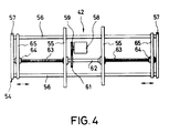
- Figure 4 is a top plan view of the work piece gripping unit.
- Figure 5 is an end elevational view, in part similar to Figure 3 and shows the specific features of the invention.
- Referring first to Figure 1, there is depicted generally a plant, such as an automotive engine assembly line, having a conveyor system and which is adapted to deliver work pieces to a delivery conveyor 11 that is positioned in a raised
area 12 of the plant and fromparts bins 13 positioned at alower level 14 in the plant. Alternatively, the device may pick up work pieces at a higher area and lower them to a lower work area or may move them between various areas depending upon the particular orientation of the plant. Empty work piece buckets are delivered to atransfer conveyor 15. - The conveyor system includes a mono- or guide rail, indicated generally by the
reference numeral 16 and having a construction as will be described. Themonorail 16 has anascending portion 17 running to the raisedarea 12 from thefloor 14 and an descendingsection 18 running in the opposite direction. A plurality ofconveyor assemblies 19 are supported along therail 16 for conveying the work pieces in the desired path and making stops at the appropriate stations. Theconveyor mechanisms 19 will be described in most detail by reference to the remaining figures and first particularly to the embodiment shown in Figures 2 through 4. - The
monorail 16 is comprised primarily of an Ibeam 21 having a generally vertically extending web and horizontally extending flanges. The Ibeam 21 is supported by means of a plurality of Lshaped brackets 22 from aroof 23. As has been previously noted, the configuration of theguide rail assembly 16 is such that the Ibeam 21 will have raised and lowered areas and also curved areas. Of course, the embodiment can be utilized in conjunction with conveyors wherein the rail is all positioned at the same elevation, but the invention has particular utility in conjunction with arrangements wherein the rail has elevating and lowering sections. - The
conveyor 19 includes a supporting and driving conveyor, indicated generally by thereference numeral 24 that is comprised of a frame having anupper portion 25 that journals adriving shaft 26 in an appropriate member. The drivingshaft 26 is driven in a manner to be described and is adapted to be drivingly coupled by means of an electrically operatedclutch 27 to a or other high friction materialtired drive wheel 28 that is engaged with the upper surface of the upper flange of the Ibeam 21. Obviously, as thewheel 28 is rotated, theconveyor 19 will traverse along the path defined by the Ibeam 21. - There are also provided for lateral stabilization and for tracking a pair of
upper guide rollers 29 that are freely journaled on theupper frame 25 and which engage the sides of the top flange of the Ibeam 21. - A
lower frame assembly 31 is suspended from theupper frame assembly 25 by means eluding at least one L shapedbracket 32. Theframe 31 supports adriving motor 33, the center of gravity of which is vertically beneath the I beam 21 for stability. Themotor 33 is a high torque, low speed direct driven motor that drives anoutput shaft 34 on which adrive pulley 35 is supported. Abelt 36 transfers drive from theshaft 34 to theshaft 26. For this purpose a drivenpulley 37 is affixed to theshaft 26. As previously noted, the electrically operatedclutch 27 drivingly couples theshaft 26 to thedrive roller 28 when it is desired to move the conveyor along therail 21. - There are provided a pair of
lower guide rollers 38 that are engaged with opposite sides of the lower flanges of the Ibeam 21 so as to aid in further stability. Anidler roller 39 and a pair of springbiased rollers 41 are also engaged with the underside of this lower flange so as to provide the desired degree of engagement of theroller 28 with the upper flange and so as to improve tracking and stability. - A gripping unit, indicated generally by the
reference numeral 42 is suspended from theframe assembly 31 and is movable vertically relative to it by means of a combined drive and suspension unit, indicated generally by thereference numeral 43. Theunit 43 includes a main driving shaft 44 that is driven from themotor shaft 34 by means of abelt 45. Anelectric clutch 46 is interposed between apulley 47 that is directly driven by thebelt 45 and the shaft 44 so as to selectively actuate the shaft 44 and raise and lower thegripping unit 42 through substantial height variations in the manner now to be described. - A pair of
gears 48 are affixed to the opposite ends of the shaft 44 and are each enmeshed with a pair of diametrically opposed drivengears 51. Thegears 51 are affixed to shafts upon whichdrums 52 are fixed. Thedrums 52 have wound on them respective lengths ofcable 53 that are connected to aframe assembly 54 of the workpiece gripping unit 42. - The
frame assembly 54 includes a pair ofcross bars 55 that are connected to perpendicularly extendingplates 56 which are capped at their opposite ends byend plates 57. - An
electric motor 58 is carried by theframe assembly 54 and drives adriving gear 59. Thedriving gear 59 is enmeshed with a drivengear 61 that is fixed to afeed shaft 62. Thefeed shaft 62 is journaled on the frame assembly by theplates portions 63 of opposite hand. The threadedportions 63 are received infeed nuts 64 that are affixed to grippingplates 65. Operation of themotor 58, which is a reversible motor, will cause thegripping plates 65 to move toward or away from each other between a spaced position as shown in the figures and a gripping position wherein a work piece may be gripped therebetween. - An electrically operated
brake 66 is associated with thedrive wheel 28 and selectively locks theconveyor 19 in position on theguide rail 21 at times as will he described. In a like manner, anelectric brake 67 is associated with the shaft 44 for locking this shaft and thegripping mechanism 55 in its vertically disposed positions. Electric power for themotors clutches brakes I beam 22 and are engaged bywipers 69 carried by theframe assembly 25. Thesewipers 69 deliver the power to apower box 71 which, in turn, is connected to acontrol box 72 so as to control the various electrical components. - There is also provided at spaced locations along the
guide rail 21position indicators 73 that are carried byangle brackets 74 and which cooperate with asensor 75 so as to provide signals to thecontrol device 72 when theconveyor 19 is at certain positions on theguide rail 17, such as at thestations - The
control mechanism 72 may include a preprogrammed control that will provide the desired sequence of operations, a typical one of which will be hereinafter described. It should be understood, however, that those skilled in the art can readily adapt the control sequences to specific applications. - When the
conveyor 19 is at a station indicated by theposition indicator 73, normally theclutches brakes brake 67 is released and the clutch 46 is engaged while thebrake 66 remains engaged. Thegripping device 54 may then be raised or lowered to the appropriate position and themotor 58 energized so as to either grip or release a work piece. - After the work piece is released or gripped, the gripping
device 42 may be again raised or lowered as desired and then the clutch 46 is released and thebrake 67 is engaged so as to lock thegripping device 42 at the desired height. - When the
conveyor 19 is ready to be moved to the next station, thebrake 66 is released and the clutch 27 is engaged so that the conveyor can move to the next station as determined by theposition indicator 73 andsensor 75. Again, the grippingdevice 42 may be raised or lowered and either grip or release a work piece. It is believed from this description that those skilled in the art will readily understand how the conveyor mechanism described can be utilized for any of a wide variety of purposes and in a wide variety of applications.
There is further provided anobstruction indicator 76 that is carried by theframe 25 of the conveyor and which will sense of an obstacle is positioned in front of theconveyor 19 and this will effect operation of thebrakes clutches - Figure 5 shows the specific embodiment of the invention which is generally similar to the embodiment of Figures 1 through 4. In this embodiment, however, the main drive motor for driving the
conveyor 19 along therail 21 is supported above the rail rather than below it. As with the earlier embodiment, the center of gravity of the drive motor is located vertically within the area of therail 21 for stability. As may be seen in Figure 5, thedrive motor 101 is supported on theupper frame 25 and has itsoutput shaft 102 coupled to theshaft 26 by means of adrive belt 103. In all other regards this embodiment is the same as the previously described embodiment and, for that reason, components which are the same as those of the previously described embodiment have been identified by the same reference numerals and further description of them is believed to be unnecessary to understand the construction and operation of this embodiment. - It should be readily apparent from the foregoing description that the described conveyor mechanism permits the use of a monorail assembly with great stability due to the positioning of the drive motor so that is center of gravity is positioned vertically within the outer periphery of the guide rail. In addition, the way in which the gripper mechanism is supported from the conveying mechanism is particularly useful in accommodating a wide variety of height differences and differences in the point at which work pieces can be picked up an released.
Claims (6)
- A monorail type conveying system comprising a single guide rail (16), a combined drive and supporting mechanism (24) carried by said guide rail (16), and electric motor means (101) for driving said conveyor (19) along said guide rail (16), said electric motor (101) being positioned with its center of gravity vertically between the sides of the guide rail (16) for stability,
characterized in that
the electric motor (101) is positioned above the guide rail (16). - A monorail type conveying system as set forth in claim 1, wherein the conveyor means (19) comprises a frictional drive wheel (28) engaged with the upper side of the monorail and a pair of tracking rollers (29) engaged with the side of the guide rail (16).
- A monorail type conveying system as set forth in claim 2, wherein the guide rail (16) comprises an I-beam (21) and the guide and tracking rollers (29) are engaged with the sides of the flange of the I-beam (21).
- A monorail type conveying system as set forth in claim 3, wherein there are a pair of guide and tracking rollers (29;38), one associated with the upper flange of the I-beam (21) and the other associated with the lower flange of the I-beam (21).
- A monorail type conveying system as set forth in one of claims 1 to 4, further including gripping means (42) carried by the combined drive and supporting mechanism (24) and vertically movable thereto, said gripping means (42) comprising means (65) for grasping and releasing a work piece.
- A monorail type conveying system as set forth in claim 5, wherein the gripping means (42) is supported for movement relative to the combined drive and supporting means (24) by means of flexible cables (53).
Applications Claiming Priority (2)
| Application Number | Priority Date | Filing Date | Title |
|---|---|---|---|
| US385576 | 1989-07-26 | ||
| US07/385,576 US5016543A (en) | 1989-07-26 | 1989-07-26 | Freight system |
Publications (2)
| Publication Number | Publication Date |
|---|---|
| EP0410084A1 EP0410084A1 (en) | 1991-01-30 |
| EP0410084B1 true EP0410084B1 (en) | 1994-04-06 |
Family
ID=23521988
Family Applications (1)
| Application Number | Title | Priority Date | Filing Date |
|---|---|---|---|
| EP90108540A Expired - Lifetime EP0410084B1 (en) | 1989-07-26 | 1990-05-07 | Freight system |
Country Status (3)
| Country | Link |
|---|---|
| US (1) | US5016543A (en) |
| EP (1) | EP0410084B1 (en) |
| DE (1) | DE69007890T2 (en) |
Families Citing this family (4)
| Publication number | Priority date | Publication date | Assignee | Title |
|---|---|---|---|---|
| JPH04101763U (en) * | 1991-02-12 | 1992-09-02 | 株式会社椿本チエイン | Hanger tilting mechanism of hanging conveyance device |
| DE102010041894A1 (en) * | 2010-10-01 | 2012-04-05 | Dürr Systems GmbH | Drive unit for conveyor, is provided with drive motors for movement of load bearing unit in guide with supporting surface, where drive motor is incorporated in trolleys guided in guide |
| DE102016210031A1 (en) * | 2016-06-07 | 2017-12-07 | Schmid Technology Systems Gmbh | Rail vehicle for a rail transport system and rail transport system |
| AT525853A1 (en) * | 2022-02-04 | 2023-08-15 | Tgw Mechanics Gmbh | Improved overhead conveyor for a picking system and transport carrier for transporting hanging goods |
Family Cites Families (16)
| Publication number | Priority date | Publication date | Assignee | Title |
|---|---|---|---|---|
| US875864A (en) * | 1907-06-27 | 1908-01-07 | John F Stout | Mail-delivery system. |
| US1340962A (en) * | 1919-09-25 | 1920-05-25 | Henry M Lane | Conveying mechanism |
| US1412831A (en) * | 1920-10-11 | 1922-04-18 | Earl T Bennington | Carrier for overhead carrier systems |
| US3018739A (en) * | 1958-01-02 | 1962-01-30 | Duff Norton Co | Monorail trolley |
| US3129671A (en) * | 1961-08-21 | 1964-04-21 | Aircraft Armaments Inc | Monorail tractor |
| US3387689A (en) * | 1965-10-21 | 1968-06-11 | Herbert C. Ovshinsky | Electromagnetic clutch and brake transmissions |
| DE2320777A1 (en) * | 1973-04-25 | 1974-11-07 | Mannesmann Ag | RAILWAY |
| FR2377963A1 (en) * | 1977-01-20 | 1978-08-18 | Delattre Levivier | Load handling grab - has winch actuating jaws mounted on slewing column and moving controlling component |
| DE3030929C2 (en) * | 1980-08-16 | 1983-01-05 | Mannesmann AG, 4000 Düsseldorf | Trolley |
| US4531460A (en) * | 1982-03-10 | 1985-07-30 | Litton Systems, Inc. | Material handling system |
| DE3218712C2 (en) * | 1982-05-18 | 1985-05-02 | Fraunhofer-Gesellschaft zur Förderung der angewandten Forschung e.V., 8000 München | Two-axis handling device for moving workpieces between any two points in a plane |
| FR2529522B1 (en) * | 1982-06-30 | 1986-12-05 | Tsubakimoto Chain Co | SELF-SUSPENDED SELF-PROPELLED CONVEYOR |
| JPS596168A (en) * | 1982-06-30 | 1984-01-13 | 株式会社椿本チエイン | Conveyor |
| DE3710494A1 (en) * | 1987-03-30 | 1988-10-27 | Schierholz Kg Louis | CONVEYOR RAILWAY WITH CHASSIS GUIDED ON AT LEAST ONE RAIL |
| DE3800107A1 (en) * | 1988-01-05 | 1989-07-13 | Horst Schmitz | Overhead transport apparatus |
| DE3801057A1 (en) * | 1988-01-15 | 1989-07-27 | Franz Gaertner | Transport apparatus for an overhead conveying apparatus |
-
1989
- 1989-07-26 US US07/385,576 patent/US5016543A/en not_active Expired - Lifetime
-
1990
- 1990-05-07 DE DE69007890T patent/DE69007890T2/en not_active Expired - Fee Related
- 1990-05-07 EP EP90108540A patent/EP0410084B1/en not_active Expired - Lifetime
Also Published As
| Publication number | Publication date |
|---|---|
| US5016543A (en) | 1991-05-21 |
| DE69007890D1 (en) | 1994-05-11 |
| DE69007890T2 (en) | 1994-07-21 |
| EP0410084A1 (en) | 1991-01-30 |
Similar Documents
| Publication | Publication Date | Title |
|---|---|---|
| US5069141A (en) | Overhead conveyor which provides increased reactive force and traction to drive wheel on ascending rail sections | |
| US10822169B2 (en) | Order picking system | |
| US5012917A (en) | Transport apparatus for an assembly line | |
| US3661280A (en) | Automatic storage and semi-automated order picking system | |
| AU2018203529B2 (en) | A rail transport bogie and a rail transportation system | |
| KR100511175B1 (en) | Conveyor for a load-moving system | |
| CN214651938U (en) | Ceramic tile storage system | |
| US5020440A (en) | Conveyor with pivotally damped workpiece carrier | |
| EP1422169B1 (en) | Warehouse with rail trolleys for storing and retrieving goods | |
| EP0379206B1 (en) | Conveyor having self-propelled carrier | |
| EP0410084B1 (en) | Freight system | |
| JPS6040304A (en) | Housing system | |
| JP2000318604A (en) | Storage conveyer for hybrid conveyer carriage | |
| US3485390A (en) | Storage system with a transfer mechanism for an article handling vehicle | |
| CN112688505B (en) | Magnetic suspension long stator coil laying vehicle system | |
| US5121695A (en) | Overhead cableway | |
| CN110615281A (en) | Automatic unloader that goes up of metal cutting | |
| JPH06158999A (en) | Segment conveyor for shielding | |
| US3865266A (en) | Load carrier transfer | |
| KR200227123Y1 (en) | Hot rolled coil automatic feeder | |
| CN216915582U (en) | Electric locomotive maintenance station | |
| RU2020088C1 (en) | Transfer loader | |
| JPH0647844Y2 (en) | Work transfer device | |
| EP0560746B1 (en) | A stacker crane transferable between warehouse aisles | |
| JPH09217600A (en) | Method for conveying material for work inside tunnel shaft, and device for alternate passage of conveying truck inside tunnel shaft |
Legal Events
| Date | Code | Title | Description |
|---|---|---|---|
| PUAI | Public reference made under article 153(3) epc to a published international application that has entered the european phase |
Free format text: ORIGINAL CODE: 0009012 |
|
| AK | Designated contracting states |
Kind code of ref document: A1 Designated state(s): DE FR |
|
| 17P | Request for examination filed |
Effective date: 19910730 |
|
| 17Q | First examination report despatched |
Effective date: 19920907 |
|
| GRAA | (expected) grant |
Free format text: ORIGINAL CODE: 0009210 |
|
| AK | Designated contracting states |
Kind code of ref document: B1 Designated state(s): DE FR |
|
| REF | Corresponds to: |
Ref document number: 69007890 Country of ref document: DE Date of ref document: 19940511 |
|
| ET | Fr: translation filed | ||
| PLBE | No opposition filed within time limit |
Free format text: ORIGINAL CODE: 0009261 |
|
| STAA | Information on the status of an ep patent application or granted ep patent |
Free format text: STATUS: NO OPPOSITION FILED WITHIN TIME LIMIT |
|
| 26N | No opposition filed | ||
| PGFP | Annual fee paid to national office [announced via postgrant information from national office to epo] |
Ref country code: DE Payment date: 20000508 Year of fee payment: 11 |
|
| PGFP | Annual fee paid to national office [announced via postgrant information from national office to epo] |
Ref country code: FR Payment date: 20000510 Year of fee payment: 11 |
|
| PG25 | Lapsed in a contracting state [announced via postgrant information from national office to epo] |
Ref country code: FR Free format text: LAPSE BECAUSE OF NON-PAYMENT OF DUE FEES Effective date: 20020131 |
|
| PG25 | Lapsed in a contracting state [announced via postgrant information from national office to epo] |
Ref country code: DE Free format text: LAPSE BECAUSE OF NON-PAYMENT OF DUE FEES Effective date: 20020301 |