EP0408902B1 - Dispositif pour déposer des produits imprimés - Google Patents
Dispositif pour déposer des produits imprimés Download PDFInfo
- Publication number
- EP0408902B1 EP0408902B1 EP90111428A EP90111428A EP0408902B1 EP 0408902 B1 EP0408902 B1 EP 0408902B1 EP 90111428 A EP90111428 A EP 90111428A EP 90111428 A EP90111428 A EP 90111428A EP 0408902 B1 EP0408902 B1 EP 0408902B1
- Authority
- EP
- European Patent Office
- Prior art keywords
- wheel
- ejecting
- stops
- ejection
- paddle wheel
- Prior art date
- Legal status (The legal status is an assumption and is not a legal conclusion. Google has not performed a legal analysis and makes no representation as to the accuracy of the status listed.)
- Expired - Lifetime
Links
- 230000000694 effects Effects 0.000 claims description 4
- 238000000151 deposition Methods 0.000 claims description 2
- 230000015572 biosynthetic process Effects 0.000 description 25
- 238000005755 formation reaction Methods 0.000 description 25
- 230000002093 peripheral effect Effects 0.000 description 8
- 230000001154 acute effect Effects 0.000 description 1
- 230000001419 dependent effect Effects 0.000 description 1
- 238000006073 displacement reaction Methods 0.000 description 1
- 230000010363 phase shift Effects 0.000 description 1
- 230000000284 resting effect Effects 0.000 description 1
- 238000009420 retrofitting Methods 0.000 description 1
- 230000001360 synchronised effect Effects 0.000 description 1
Images


Classifications
-
- B—PERFORMING OPERATIONS; TRANSPORTING
- B65—CONVEYING; PACKING; STORING; HANDLING THIN OR FILAMENTARY MATERIAL
- B65H—HANDLING THIN OR FILAMENTARY MATERIAL, e.g. SHEETS, WEBS, CABLES
- B65H29/00—Delivering or advancing articles from machines; Advancing articles to or into piles
- B65H29/66—Advancing articles in overlapping streams
- B65H29/6609—Advancing articles in overlapping streams forming an overlapping stream
-
- B—PERFORMING OPERATIONS; TRANSPORTING
- B65—CONVEYING; PACKING; STORING; HANDLING THIN OR FILAMENTARY MATERIAL
- B65H—HANDLING THIN OR FILAMENTARY MATERIAL, e.g. SHEETS, WEBS, CABLES
- B65H29/00—Delivering or advancing articles from machines; Advancing articles to or into piles
- B65H29/38—Delivering or advancing articles from machines; Advancing articles to or into piles by movable piling or advancing arms, frames, plates, or like members with which the articles are maintained in face contact
- B65H29/40—Members rotated about an axis perpendicular to direction of article movement, e.g. star-wheels formed by S-shaped members
-
- B—PERFORMING OPERATIONS; TRANSPORTING
- B65—CONVEYING; PACKING; STORING; HANDLING THIN OR FILAMENTARY MATERIAL
- B65H—HANDLING THIN OR FILAMENTARY MATERIAL, e.g. SHEETS, WEBS, CABLES
- B65H2301/00—Handling processes for sheets or webs
- B65H2301/40—Type of handling process
- B65H2301/44—Moving, forwarding, guiding material
- B65H2301/447—Moving, forwarding, guiding material transferring material between transport devices
- B65H2301/4473—Belts, endless moving elements on which the material is in surface contact
- B65H2301/44732—Belts, endless moving elements on which the material is in surface contact transporting articles in overlapping stream
-
- B—PERFORMING OPERATIONS; TRANSPORTING
- B65—CONVEYING; PACKING; STORING; HANDLING THIN OR FILAMENTARY MATERIAL
- B65H—HANDLING THIN OR FILAMENTARY MATERIAL, e.g. SHEETS, WEBS, CABLES
- B65H2301/00—Handling processes for sheets or webs
- B65H2301/40—Type of handling process
- B65H2301/44—Moving, forwarding, guiding material
- B65H2301/447—Moving, forwarding, guiding material transferring material between transport devices
- B65H2301/44765—Rotary transport devices with compartments
-
- B—PERFORMING OPERATIONS; TRANSPORTING
- B65—CONVEYING; PACKING; STORING; HANDLING THIN OR FILAMENTARY MATERIAL
- B65H—HANDLING THIN OR FILAMENTARY MATERIAL, e.g. SHEETS, WEBS, CABLES
- B65H2511/00—Dimensions; Position; Numbers; Identification; Occurrences
- B65H2511/40—Identification
- B65H2511/414—Identification of mode of operation
Definitions
- the present invention relates to a device for laying out, in particular, folded printed products according to the preamble of claim 1.
- Such a device is known from EP-PS 0 059 873 or the corresponding US-PS 4,434,979.
- This has a disk-shaped ejector wheel which is eccentrically mounted with respect to the impeller and which engages around the shaft of the impeller. Distributed around the circumference of the ejection wheel are twice as many stops as the paddle wheel has pockets. The ejection wheel is driven at half the speed of the paddle wheel, so that each pocket is assigned a stop for ejecting the printed products shot into the pockets.
- a delivery conveyor is provided below the paddle wheel, which is driven at a speed which corresponds to the peripheral speed of the stops.
- Each printed product shot into a pocket of the paddle wheel initially runs onto the relevant stop as a result of the relative speed between the stops and the pockets and is expelled from the pocket in the course of the further rotation of the paddle wheel and the ejection wheel and at a distance which is the distance between the stops corresponds, deposited in scale formation on the delivery conveyor.
- a device for forming stacks from signature sheets ejected from a paddle wheel and conveying away these stacks in scale formation is known from EP-OS 0 179 992. This has a stationary stop, against which the signature sheets abut and are brought to a standstill, as seen in the direction of rotation of the impeller. The signature sheets ejected from the blades of the paddle wheel float in free fall onto a holding device or the signature sheets already placed thereon.
- the holding device in each case holds back the bottom signature sheet of a stack against the frictional entrainment by the stack which has previously been formed and is to be transported away.
- the Delivery conveyor and the paddle wheel are synchronized in such a way that the delivery conveyor in each case conveys away a stack as soon as it has the desired number of signature sheets.
- the signature sheets are braked very strongly at the stop, which can damage them.
- either one pocket of the paddle wheel can now be assigned a stop or two or more pockets can be assigned a common stop. If a stop acts on the printed product in a single pocket, the printed products are laid out individually, the distance between the leading edges of the printed products corresponding to the distance between the stops.
- the number of ejection-effective stops it is now possible for the printed products arranged in two or more pockets to run onto a common stop and to be ejected from the paddle wheel lying one above the other. The desired formation is thus formed directly when the printed products are laid out without the aid of means provided outside the paddle wheel and the ejection arrangement.
- the number of ejector-effective stops can be halved. This makes it possible to switch from laying out in a shed formation, in which each printed product is ejected individually from the paddle wheel, into a shed formation, in which two printed products are ejected together and one above the other, without changing the speed ratio between the paddle wheel and the ejection arrangement .
- the ejection arrangement has two ejection wheels, each of which has the same number of stops. By aligning the stops of the two ejection wheels towards one another or by rotating the two stop wheels against one another by half a division of the stops, the number of stops which have an effect on ejection can be halved or doubled.
- each printed product is braked in the same optimal manner by a first ejection wheel and the relevant bucket and guided to the stops of a second ejection wheel.
- retrofitting of known devices for example a device according to EP-PS 0 059 873 or the corresponding US-PS 4,434,979, is possible without changing the paddle wheel or the ejection wheel.
- a delivery conveyor according to claim 9 is provided below the paddle wheel.
- the printed products are ejected from the paddle wheel and deposited on the delivery conveyor at essentially the same speed, seen in the conveying direction of the delivery conveyor, and placed on the delivery conveyor as they are transported away from the latter. There is therefore hardly any relative speed between the belt conveyor and the printed products to be placed on it, which leads to the formation of a particularly precise scale formation.
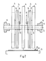
- the device shown in FIGS. 1 and 2 has three paddle wheels 14 of a printing machine which are seated on a common shaft 10 in a rotationally fixed manner and are spaced apart in the direction of the axis 12 of the shaft 10.
- the shaft 10 is freely rotatably mounted on stationary bearings 16 and driven in the direction of rotation U at the speed n1.
- Each paddle wheel has ten pockets 18, which are open to the rear in the direction of arrow U and are separated from one another by blades 20 and are closed off in their leading region by a base 22.
- the orbit of the trailing free ends 20 'of the blades 20 is indicated by dash-dotted lines and designated 20' '(Fig. 1).
- An ejection arrangement 24 is provided in the area between each two paddle wheels 14. This has two ejection wheels 28, 30 driven in rotation around a dash-dot line of rotation 26 in the direction of arrow U.
- the speed n2 of the ejection wheels 28, 30 is half the speed n1 of the paddle wheels 14.
- the ejection wheels 28, 30 are disc-shaped, freely rotatably mounted on a common bearing arrangement 32 and encompass the shaft 10. The bearing arrangement 32 is further down in the 3 explained in more detail.
- the two ejection wheels 28, 30 are of the same size and are sawtooth-shaped on their circumference.
- the trailing flanks seen in the direction of rotation U form stops 34 for the printed products 36 shot into the pockets 18 for ejecting them from the paddle wheel 14.
- Each ejection wheel 28, 30 has ten stops 34 evenly distributed on the circumference, the two ejection wheels 28, 30 are rotated by half a division of the stops 34 against each other.
- the ejection arrangement 24 thus has twenty stops 34.
- the flat flanks 38 leading in the direction of the arrow U have a kink 40 in their central region, the respective leading flank part 38 ', seen in the radial direction, with the circular movement path 40' of the kink 40 indicated by dash-dotted lines forming a larger angle than the trailing flank part 38 ''.
- Both ejection wheels 28, 30 have two slot-shaped passages 42 diametrically opposite one another, running centrally to the axis of rotation 26.
- a bolt-shaped fastening element 44 for releasably clamping the two ejection wheels 28, 30 runs through the corresponding passages 42 of both ejection wheels 28, 30.
- the fastening element 44 is, for example, a screw-nut connection.
- a pinion 46 On the shaft 10, a pinion 46, indicated by a dot-dash line, also sits in a rotationally fixed manner for each ejection arrangement 24 and meshes with a corresponding internal toothing on the ejection wheel 30, which is not shown in FIGS. 1 and 2. 2, a linkage is designated in FIG. 2 by means of which the pivot position of the bearing arrangement 32 for the ejection wheels 28, 30 can be adjusted.
- a delivery conveyor 50 for example a belt conveyor, the conveying direction of which is denoted by F.
- F conveying direction of which is denoted by F.
- the conveying speed v1 corresponds to the peripheral speed v2 of the ejection wheels 28, 30.
- the fold 36 ' seen in the direction of arrow U, shot into the pockets 18 of the paddle wheel 14
- Printed products 36 are pushed out of the pockets 18 by means of the ejection arrangement 24 and placed in scale formation S on the delivery conveyor 50, each printed product 36 resting like a roof tile on the printed product 36 leading in the conveying direction F.
- the distance between two stops 34 is indicated in FIG. 1 by the double arrow A and the distance between the folds 36 'of the printed products 36 laid out in scale formation S is denoted by A'. Since the speeds v1 and v2 are the same, the distance A corresponds to the distance A '.
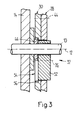
- FIG. 3 shows the bearing arrangement 32 for the two ejection wheels 28, 30 enlarged in a section along the line III-III of FIG. 1.
- the paddle wheel 14 and the pinion 46 are seated on the shaft 10 in a rotationally fixed manner.
- the bearing element is connected to the linkage 48 (see FIG. 2) and is adjustable in its pivoting position about the axis 12.
- the two ejection wheels 28, 30 are seated on the bearing element 52 and can be freely rotated about the axis of rotation 26 with respect thereto.
- the ejector wheel 30 adjacent to the pinion 46 has on the side facing the pinion 46 has a round recess 54 which is central to the axis of rotation 26 and has internal teeth 56. This meshes with a corresponding toothing of pinion 46.
- Fastening element 44 which is only indicated by dash-dotted lines in this figure, transmits the rotational movement of ejection wheel 30 to ejection wheel 28.
- the reduction between pinion 36 and ejection wheels 28, 30 is designed such that the two ejection wheels 28, 30 are driven at half the speed with respect to shaft 10.
- the two ejection wheels 28, 30 can be rotated relative to one another by half a tooth pitch of an ejection wheel 28 or 30.
- the stops 34 of the two ejection wheels 28, 30 are aligned with one another.
- the ejection arrangement 24 has only ten ejection-effective stops 34. All parts shown in these two figures correspond to the parts described above and shown in FIGS. 1 to 3. They are therefore only mentioned again to the extent that this is necessary for an understanding of FIGS. 4 and 5.
- the paddle wheels 14, which are non-rotatably seated on the shaft 10, of which only one is visible, are driven to rotate in the direction of rotation U at the speed n1.
- the two aligned ejection wheels 28, 30 rotate in the direction of arrow U around the schematically indicated axis of rotation 26 at the speed n2, which is half the speed n1 of the paddle wheel 14. This has the consequence that two pockets 18 each have a common stop 34 is assigned.
- the scale formation S laid out on the delivery conveyor 50 has two congruent portions printed products 36 placed one on top of the other, which, as seen in the direction of conveyance F, each resemble roof tiles on the preceding pair of printed products 36.
- the conveying speed v1 of the delivery conveyor 50 corresponds to the circumferential speed v2 of the ejection wheels 28, 30.
- the distance B designated between two successive stops 34 corresponds to the distance B 'between the folds 36' of the printed products 36 arranged in the scale formation S, seen in the conveying direction F .
- the device for laying out printed products 36 shown in FIGS. 1 to 5 operates in the operating mode shown in FIG. 1 as follows: A printed product 36 with its fold 36 ′ is inserted into each pocket 18 of the paddle wheel 14 in a known manner. shot in advance and comes to rest with his fold 36 'on the bottom 22 of the pocket 18 concerned. In the course of the further rotation of the paddle wheel 14, the printed product 36 runs with its fold 36 'as a result of the different speed between the bottom 22 and the stop 34 onto a stop 34 of the one paddle wheel 28 or 30 and is braked to the speed of the stop 34.
- the printed product 36 is clamped and held in the area of the fold 36 'between the pocket 18, seen in the radial direction, against the blade 20 which delimits the outside and a flatter part 38''of the other ejection wheel 30 or 28.
- the printing product in question 36 is displaced in the pocket 18 against the direction of the arrow U in accordance with the relative speed between the paddle wheel 14 and the ejection wheels 28, 30.
- the printed product 36 comes into contact with the rear area seen in the direction of rotation U on the delivery conveyor 50 or the last printed product 36 placed thereon and is finally released in the area of the fold 36 'by the bucket wheel 14 by the free end 20' of the bucket 20 concerned passes the stop 34.
- the blades 20 and flank parts 38 ′′ each stand at an acute angle to one another in the area in which the relevant stops 34 have an ejection effect and thus hold the corresponding printed products 36 in a wedge shape.
- the device shown in FIGS. 1 to 5 operates as follows in an operating mode according to FIGS. 4 and 5:
- the ejection arrangement 24 now has the same number of ejection stops 34 as the paddle wheel 14, pockets 18, the ejection wheels 28, 30 with respect to the paddle wheel 14 revolve at half speed n2.
- each stop 34 is responsible for ejecting two printed products 36 shot into adjacent pockets 18.
- the printed product 36 shot into the pocket 18 leading in the direction of the arrow U comes to rest on the floor 22 in question and, owing to the relative speed between the floor 22 and the stop 34 in question, hits it, is braked and, in the pocket 18, counter to the direction of the arrow U, pushed backwards.
- the printed product 36 shot into the next trailing pocket 18 as seen in the direction of the arrow U also comes into contact with the relevant floor 22 and runs onto the same stop 34 as the printed product 36 shot into the leading pocket 18.
- the printed product 36 shot into the rear pocket is clamped and held between the pocket 18 in question in the radial direction toward the outside and the flank part 38 ′. So there are two printed products 36 with their fold 36 'on the same stop 34.
- the printed product 36 arranged in the outer pocket 18 leading in each case is first ejected from the pocket 18 and released, this being placed on the delivery conveyor 50 at a distance B ′ from the printed products 36 already laid out in scale formation S (cf. Fig. 4).
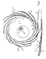
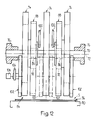
- the device shown in FIGS. 6 to 11 in a view and partially in a simplified manner and shown in FIG. 12 in a side view in the direction of the arrow XII in FIG. 6 has three, non-rotatably mounted on a shaft 70 in the direction of the axis 72 of the shaft 70 Paddle wheels 74 on.
- Figures 6 to 11 are the Paddle wheels 74 only partially shown.
- the delivery device is described in detail with reference to FIGS. 6 and 12; in Figures 7 to 11 only those reference numerals are given which are necessary for understanding.
- the shaft 70 is freely rotatably mounted in fixed bearings 76 and driven in the direction of rotation U at the speed n1.
- Each paddle wheel 74 has ten pockets 78, which are open towards the rear in the direction of rotation U and are defined by blades 80 in the radial direction and are delimited by a base 82 in their leading end.
- the rear free end of the blades 80 is designated 80 '(Fig. 6).
- An ejection arrangement designated by 84 in each case has a first ejection wheel 88 driven between the blade wheels 74 and rotating around the axis of rotation 86 (cf. in particular FIG. 12).
- the first ejection wheel 88 is designed in the shape of a disk ring and is freely rotatably mounted on a bearing arrangement 92 indicated by the dashed line in FIG. 12.
- the bearing arrangement 92 is of exactly the same design as the bearing arrangement 32 shown in FIG.
- the first ejection wheel 88 in the region of the bearing arrangement 92 being of the same design as the ejection wheel 30 according to FIG. 3.
- the first ejection wheel 88 is Via a pinion, which is seated in a rotationally fixed manner on the shaft 70 and meshes with an internal toothing on the first ejection wheel 88, is driven at a speed n2 which is half the speed n1 of the paddle wheel 74.
- the first ejector wheel 88 is sawtooth-shaped on its circumference, the twenty steep flanks trailing, as seen in the direction of rotation U, as stops 94 for those shot into the pockets 78 of the paddle wheels 74
- Print products 96 serve.
- the flat flanks leading in the direction of arrow U with respect to the stops 94 are designated 98.
- the eccentric bearing arrangement 92 can be adjusted in its rotational position with respect to the axis 72 by means of a linkage 100 shown in FIG. 12, in order to hold printed products 96 of different thicknesses between the blades 80 and the flanks 90 in a known manner.
- the ejection arrangement 84 has a second ejection wheel 102 in the area between the shaft 70 and the radial end area of the first ejection wheel 88, as seen in the direction of the axis 72, outside the two outer vane wheels 74. As indicated by dash-dotted lines in FIG. 12, it would also be conceivable for the two second ejection wheels 102 or two additional second ejection wheels to be provided in the region between the first ejection wheels 88 and the central paddle wheel 74.
- the second ejection wheels 102 are freely rotatably mounted on a holder 104, which is only schematically indicated in FIG.
- the drive element 106 is preferably a chain drive, which in each case operatively connects the second ejection wheel 102 to the shaft 70 with a reduction ratio of 2: 1.
- the second ejector wheel 102 is sawtooth-shaped on its circumference, the steep flanks trailing in the direction of rotation U being designed as stops 108 for the leading folds 96 'of the printed products 96.
- the number of stops 108 corresponds to the number of pockets 78 of each paddle wheel 74. Since the speed n3 of the second ejection wheel 102 is now half the speed n1 of the paddle wheels 74, a single stop 108 of the second ejection wheel 102 hits two pockets 78.
- the second ejection wheels 102 can be brought from the area of action on the printed products 96 by means of the holder 104, for example by pivoting in the direction of arrow B about the axis 72. By pivoting back against the direction of the arrow B into the position shown in the figures, the second ejector wheel 102 in turn becomes ejection effective.
- a delivery conveyor 110 for example a belt conveyor, which is driven in the conveying direction F is provided below the paddle wheels 74 and the ejection arrangement 84.
- the conveying speed v1 of the delivery conveyor 110 corresponds to the peripheral speed v2 of the second ejection wheel 102.
- the delivery conveyor 110 is driven at a conveyor speed v1 which corresponds to the peripheral speed v3 corresponds to the first ejection wheel 88.
- a guide element 114 runs from a feed area 112 of the printed products 96 to the area above the delivery conveyor 110 for the open trailing edges of the printed products 96, which are labeled 96 ′′ and are opposite the fold 96 ′.
- the printed products 96 placed thereon lie on the delivery conveyor 110 in a shingled formation S, two respective printed products 96 lying congruently one above the other lying on the leading pair of printed products 96 in the manner of roof tiles.
- the distance C 'between the leading folds 96' of two adjacent pairs of printed products 96 corresponds to the distance C between the stops 108 of the second ejection wheel 102.
- the printed products 96 become, if the second ejection wheel 102 is pivoted out of the area affected by the printed products 96, is deposited in a scale formation S on the delivery conveyor 110, in which each printed product 96 rests on the leading one in the manner of a roof tile.
- the distance between the folds 96 'of the printed products 96 deposited in this manner in scale form corresponds to the distance between the stops 94 of the first ejection wheel 88, designated C''.
- the second ejection wheel 102 is approximately half the diameter of the first ejection wheel 88, for example, and points also half as many stops 108 as the first ejection wheel 88 has stops 94.
- the distance C therefore corresponds to the distance C ′′.
- FIGS. 6 and 12 illustrate the functioning of the embodiment of the delivery device shown in FIGS. 6 and 12 for six different phases of a working cycle.
- a printed product 96 with its fold 96 ' is shot in advance in each pocket 78.
- the fold 96 ' comes to rest on the floor 82, as a result of which the printed product 96 is braked to the speed of the floor 82.
- the printed product 96 runs onto a stop 94 as a result of the relative speed between the base 82 and the stops 94 of the first ejection wheel 88.
- the printed product 96 is clamped in the area of the fold 96 'by the flank 98 in question and the shovel 80 delimiting the pocket 78 in the radial direction and is successively ejected from the pocket 78 against the direction of rotation U.
- the trailing edge 96 ′′ comes into contact with the guide element 114.
- the printed product 96 bumps against a stop 108 as a result of the relative speed between the stops 94 of the first ejection wheel 88 and the stops 108 of the second ejection wheel 102, as shown in FIG. 7.
- the printed product 96 is at the relative speed between the Paddle wheels 74 and the relevant stop 108 pushed out of the pocket 78, as shown in FIG. 7.
- the trailing edge 96 ′′ still slides along the guide element 114. Shortly thereafter, the relevant blade 80 runs away from the fold 96 ', as a result of which the printed product 96 lies on the scale formation S.
- next printed product 96 trailing in the direction of arrow U is likewise held in the region of the fold 96 'between the relevant blade 80 and the relevant flank 98 of the first ejection wheel 88 and is in contact with the stop 94, as a result of which this is due to the relative speed between the first ejection wheel 88 and the paddle wheels 74 is pushed out of the pocket 78 (FIGS. 9 and 10).
- the trailing edge 96 ′′ slides from the guide element 114 and the printed product 96 lies down with its trailing area on the printed product 96 previously deposited on the scale formation S.
- the printed product 96 to be deposited runs with its fold 96 ′ onto the same stop 108 of the second ejection wheel 102 on which the previously stored printed product 96 has already come into contact (FIG. 11).
- the printed product 96 still held in the pocket 78 with the area of its fold 96 'comes with its trailing edge 96'' to lie exactly over the trailing edge 96 ′′ of the previously stored printed product 96.
- the fold 96 ' is also released due to the relative speed between the paddle wheels 74 and the stop 108 of the second ejection wheel 102, as a result of which the printed product 96 comes to lie congruently on the previously stored printed product 96.
- each printed product 96 comes to lie in the same way between the relevant blade 80 and the corresponding flank 98 of the first ejection wheel 88 and is held by it.
- the delivery device By pivoting the second ejection wheel 102 in the direction of arrow B (FIG. 6) from the area of action on the printed products 96, the delivery device works exactly the same as the device known, for example, from EP-PS 0 059 873 and US-PS 4,434,979.
- the delivery conveyor 110 is now driven in accordance with the peripheral speed v3 of the first ejection wheel 88.
- Each printed product 96 shot into a pocket 78 of the paddle wheels 74 in the feed area 112 comes to rest with its fold 96 ′ on the bottom 82.
- the printed product 96 runs onto this stop 94.
- the printed product 96 is held in the region of its leading fold 96 'by the flank 98 and the blade 80.
- the printed product 96 is pushed out of the pocket 78 counter to the direction of rotation U, the trailing edge 96 ′′ of the printed product 96 coming into contact with the guide element 114 and along this slides to the delivery conveyor 110.
- the leading fold 96 'now does not run onto a stop 108 of the second ejection wheel 102, but is ejected from the pocket 78 and released by the first ejection wheel 88.
- each printed product 96 is placed on the leading printed product 96 like a roof tile.
- the distance between the folds 96 ′ of the stored printed products 96 corresponds to the distance C ′′ between the stops 94 of the first ejection wheel 88.
Landscapes
- Engineering & Computer Science (AREA)
- Mechanical Engineering (AREA)
- Discharge By Other Means (AREA)
- Handling Of Cut Paper (AREA)
- Treatment Of Fiber Materials (AREA)
Claims (9)
- Dispositif pour délivrer des produits imprimés notamment pliés, comportant un moulinet (4), entraîné en rotation, d'une machine d'imprimerie et un dispositif d'éjection (24) en forme de roue, qui est monté de façon excentrée par rapport au moulinet et peut être entraîné dans le même sens de rotation et avec une vitesse circonférentielle plus faible que le moulinet et comporte des butées (34), situées sur sa périphérie et servant à éjecter les produits imprimés (36), qui sont insérés dans des logements (18) du moulinet et rencontrent tout d'abord les butées en raison de la vitesse relative entre les butées et les logements, à une distance prédéterminée hors des logements, caractérisé en ce que le nombre des butées (34;94,108) actives pour l'éjection est modifiable.
- Dispositif selon la revendication 1, caractérisé en ce que le nombre des butées (34;94,108) actives pour l'éjection peut être réduit de moitié.
- Dispositif selon la revendication 2, caractérisé en ce que le dispositif d'éjection (24) possède deux roues d'éjection (28,30) montées sur le même axe, qui comportent le même nombre de butées (34) et peuvent être décalées l'une par rapport à l'autre sur un décalage égal à la moitié du pas (B) de répartition des butées, à partir d'une position dans laquelle, lorsqu'on regarde dans la direction circonférentielle (U), à mi-distance entre deux butées (34) de la première roue (28,30) d'éjection est disposée respectivement une butée (34) de l'autre roue (30,28) d'éjection.
- Dispositif selon la revendication 3, caractérisé en ce que les roues d'éjection (28,30) sont disposées selon une disposition annulaire de manière à entourer l'arbre (10) du moulinet (14) et sont montées pivotantes sur un dispositif de support (32) de préférence commun aux deux roues d'éjection (28,30).
- Dispositif selon la revendication 4, caractérisé en ce que le dispositif de support (32) est monté sur l'arbre (10) du moulinet (14) et que sa position est de préférence modifiable dans la direction circonférentielle de l'arbre (10) et qu'au moins une roue d'éjection (30) possède une denture intérieure (56), qui engrène avec un pignon (46) raccordé avec blocage en rotation à l'arbre (10).
- Dispositif selon l'une des revendications 3 à 5, caractérisé en ce que le nombre des butées (34) sur chaque roue d'éjection (28,30) correspond au nombre des logements (18) du moulinet (14) et que les roues d'éjection (28,30) peuvent être entraînées avec un nombre de tours (n2) égale à la moitié de celui du moulinet (14).
- Dispositif selon la revendication 1 ou 2, caractérisé en ce que le dispositif d'éjection (84) comporte une première roue d'éjection (88), qui est montée de façon excentrée par rapport au moulinet (74) et qui entour l'arbre (70) du moulinet (74), et une seconde roue d'éjection (102), qui est montée d'une manière excentrée différente, peut être entraînée avec une vitesse circonférentielle plus faible (v2) et possède un diamètre plus faible et un nombre plus faible de butées (108) que la première roue d'éjection (88) et qui est disposée à l'extérieur de l'arbre (70) et peut au choix être amenée en prise avec les produits imprimés (96) ou en être écartée.
- Dispositif selon la revendication 7, caractérisé en ce que la première roue d'éjection (88) possède un nombre de butées (94;108) double du nombre de logements (78) que comporte le moulinet (74) et la seconde roue d'éjection comporte un nombre de butées égal au nombre de logements que comporte le moulinet, et les deux roues d'éjection (88,102) peuvent être entraînées avec un nombre de tours (n2,n3) égale à la moitié de celui du moulinet (74).
- Dispositif selon l'une des revendications 3 à 8, caractérisé en ce qu'au-dessous du moulinet (14,74) il est prévu un convoyeur de sortie (50,110) dont la direction d'entraînement (F) correspond au sens de rotation (U) du moulinet (14,74) et dont la vitesse d'entraînement (v1) correspond essentiellement à la vitesse circonférentielle (v2,v3) de la roue d'éjection (28,30; 88,102) qui est active pour l'éjection lors du dépôt des produits imprimés (36,94).
Applications Claiming Priority (2)
| Application Number | Priority Date | Filing Date | Title |
|---|---|---|---|
| CH268089 | 1989-07-18 | ||
| CH2680/89 | 1989-07-18 |
Publications (2)
| Publication Number | Publication Date |
|---|---|
| EP0408902A1 EP0408902A1 (fr) | 1991-01-23 |
| EP0408902B1 true EP0408902B1 (fr) | 1993-09-01 |
Family
ID=4239163
Family Applications (1)
| Application Number | Title | Priority Date | Filing Date |
|---|---|---|---|
| EP90111428A Expired - Lifetime EP0408902B1 (fr) | 1989-07-18 | 1990-06-18 | Dispositif pour déposer des produits imprimés |
Country Status (5)
| Country | Link |
|---|---|
| US (1) | US5125645A (fr) |
| EP (1) | EP0408902B1 (fr) |
| JP (1) | JP2920779B2 (fr) |
| DE (1) | DE59002539D1 (fr) |
| RU (1) | RU2003617C1 (fr) |
Cited By (2)
| Publication number | Priority date | Publication date | Assignee | Title |
|---|---|---|---|---|
| DE10007548A1 (de) * | 2000-02-18 | 2001-08-23 | Heidelberger Druckmasch Ag | Schaufelradanordnung für flächige Exemplare |
| DE102006021361A1 (de) * | 2006-05-08 | 2007-11-22 | Koenig & Bauer Aktiengesellschaft | Auslageeinrichtung zur Auslage von Druckprodukten an einem Falzapparat |
Families Citing this family (11)
| Publication number | Priority date | Publication date | Assignee | Title |
|---|---|---|---|---|
| FR2718723B1 (fr) * | 1994-04-15 | 1996-07-12 | Heidelberg Harris Sa | Dispositif de sortie de cahiers d'une roue à aubes. |
| US5803705A (en) * | 1997-04-03 | 1998-09-08 | Xerox Corporation | Disk type inverter-stacker with improved sheet handling slots for different paper weights |
| US6131904A (en) * | 1998-09-01 | 2000-10-17 | Goss Graphic Systems, Inc. | Stripping mechanism for a delivery fly assembly |
| EP1125875B1 (fr) | 2000-02-18 | 2004-07-07 | Heidelberger Druckmaschinen Aktiengesellschaft | Arrangement de roues à aubes pour exemplaires plats |
| DK1193201T3 (da) | 2000-10-02 | 2004-03-08 | Ferag Ag | Fremgangsmåde og anordning til dannelse af en dobbeltskelformation af trykkeriprodukter |
| US6832886B2 (en) | 2001-07-27 | 2004-12-21 | C. G. Bretting Manufacturing Co., Inc. | Apparatus and method for stacking sheets discharged from a starwheel assembly |
| US6877740B2 (en) | 2003-07-30 | 2005-04-12 | C.G. Bretting Manufacturing Company, Inc. | Starwheel feed apparatus and method |
| US7422212B2 (en) | 2005-06-21 | 2008-09-09 | Graphic Management Associates, Inc. | Transfer wheel |
| DE102008000026B3 (de) * | 2008-01-10 | 2009-02-26 | Koenig & Bauer Aktiengesellschaft | Vorrichtung zum Auslegen von Druckerzeugnissen auf einem Transportband mit einem Schaufelrad |
| JP2009286540A (ja) * | 2008-05-28 | 2009-12-10 | Komori Corp | 羽根車装置 |
| DE102009002451B4 (de) * | 2009-04-17 | 2013-08-08 | Koenig & Bauer Aktiengesellschaft | Schuppenauslegevorrichtung |
Family Cites Families (2)
| Publication number | Priority date | Publication date | Assignee | Title |
|---|---|---|---|---|
| US2172364A (en) * | 1937-02-12 | 1939-09-12 | Hoe & Co R | Delivery mechanism |
| DE3108681A1 (de) * | 1981-03-07 | 1982-09-30 | M.A.N.- Roland Druckmaschinen AG, 6050 Offenbach | "einrichtung zur entnahme von druckexemplaren aus den schaufelraedern eines falzapparates" |
-
1990
- 1990-06-18 DE DE90111428T patent/DE59002539D1/de not_active Expired - Fee Related
- 1990-06-18 EP EP90111428A patent/EP0408902B1/fr not_active Expired - Lifetime
- 1990-07-09 US US07/549,566 patent/US5125645A/en not_active Expired - Fee Related
- 1990-07-17 RU SU904830473A patent/RU2003617C1/ru active
- 1990-07-18 JP JP2190353A patent/JP2920779B2/ja not_active Expired - Lifetime
Cited By (3)
| Publication number | Priority date | Publication date | Assignee | Title |
|---|---|---|---|---|
| DE10007548A1 (de) * | 2000-02-18 | 2001-08-23 | Heidelberger Druckmasch Ag | Schaufelradanordnung für flächige Exemplare |
| DE102006021361A1 (de) * | 2006-05-08 | 2007-11-22 | Koenig & Bauer Aktiengesellschaft | Auslageeinrichtung zur Auslage von Druckprodukten an einem Falzapparat |
| DE102006021361B4 (de) * | 2006-05-08 | 2014-01-23 | Koenig & Bauer Aktiengesellschaft | Auslageeinrichtung zur Auslage von Druckprodukten an einem Falzapparat |
Also Published As
| Publication number | Publication date |
|---|---|
| DE59002539D1 (de) | 1993-10-07 |
| EP0408902A1 (fr) | 1991-01-23 |
| RU2003617C1 (ru) | 1993-11-30 |
| JP2920779B2 (ja) | 1999-07-19 |
| JPH03102064A (ja) | 1991-04-26 |
| US5125645A (en) | 1992-06-30 |
Similar Documents
| Publication | Publication Date | Title |
|---|---|---|
| DE2732591C2 (de) | Einrichtung zum Abbauen eines Stapels von biegsamen Flächengebilden | |
| EP0408902B1 (fr) | Dispositif pour déposer des produits imprimés | |
| DE3404459C2 (fr) | ||
| EP0059873B1 (fr) | Dispositif de prélèvement d'imprimés des disques de réception d'un appareil de pliage | |
| DE2448200C2 (de) | Stapelvorrichtung zum Aufnehmen und geordneten Stapeln von Dokumenten | |
| DE3230752A1 (de) | Falzbogenanleger | |
| DE2535123A1 (de) | Vorrichtung zum umwenden von flachmaterialstuecken | |
| EP0340434B1 (fr) | Appareil délivrant des articles pliés et comportant une roue à aubes | |
| DE3603285C2 (de) | Zusammentragmaschine | |
| DE4316051A1 (de) | Einrichtung zum Abbremsen von Druckprodukten in dem Auslegeschaufelrad eines Falzapparates | |
| EP0677471B1 (fr) | Dispositif de sortie d'exemplaires d'une roue à aubes | |
| EP0390736B1 (fr) | Dispositif de réduction de la vitesse d'impact des imprimés dans le fond d'une roue à aubes | |
| DE2409741C2 (de) | Vorrichtung zum Schneiden und/oder Rillen von Zuschnitten aus Faltmaterial | |
| DE3541594A1 (de) | Vorrichtung zum beschicken einer verarbeitungseinrichtung fuer biegsame, flaechige erzeugnisse, insbesondere druckprodukte | |
| CH677778A5 (fr) | ||
| CH679478A5 (fr) | ||
| DE1574161C3 (de) | Maschine zum Stapeln und Einwickeln einer vorbestimmten Anzahl gleicher Münzen | |
| CH667427A5 (de) | Zyklisch arbeitende maschine zum sammeln von signaturen. | |
| EP0607753B1 (fr) | Procédé et dispositif pour former un courant de produits imprimés pliés se chevauchant | |
| DE2122493A1 (de) | Verfahren und Vorrichtung zum Umfalten der Schließklappe von Briefumschlagen od. dgl | |
| CH666862A5 (de) | Laengsfalzvorrichtung. | |
| DE2633675A1 (de) | Geraet zum trocknen | |
| DE19627830A1 (de) | Vorrichtung zum Zubringen von Druckereiprodukten zu einem Wegförderer | |
| DE2229531A1 (de) | Einrichtung zum bilden eines stapels aus biegsamen flaechengebilden | |
| DE2033488B2 (de) | Vorrichtung zum vereinzeln eines stapels gefalteter oder gebundener druckereierzeugnisse |
Legal Events
| Date | Code | Title | Description |
|---|---|---|---|
| PUAI | Public reference made under article 153(3) epc to a published international application that has entered the european phase |
Free format text: ORIGINAL CODE: 0009012 |
|
| 17P | Request for examination filed |
Effective date: 19901010 |
|
| AK | Designated contracting states |
Kind code of ref document: A1 Designated state(s): CH DE FR GB IT LI SE |
|
| 17Q | First examination report despatched |
Effective date: 19930204 |
|
| GRAA | (expected) grant |
Free format text: ORIGINAL CODE: 0009210 |
|
| AK | Designated contracting states |
Kind code of ref document: B1 Designated state(s): CH DE FR GB IT LI SE |
|
| REF | Corresponds to: |
Ref document number: 59002539 Country of ref document: DE Date of ref document: 19931007 |
|
| GBT | Gb: translation of ep patent filed (gb section 77(6)(a)/1977) |
Effective date: 19930917 |
|
| ET | Fr: translation filed | ||
| ITF | It: translation for a ep patent filed |
Owner name: SOCIETA' ITALIANA BREVETTI S.P.A. |
|
| PGFP | Annual fee paid to national office [announced via postgrant information from national office to epo] |
Ref country code: FR Payment date: 19940519 Year of fee payment: 5 |
|
| PGFP | Annual fee paid to national office [announced via postgrant information from national office to epo] |
Ref country code: SE Payment date: 19940524 Year of fee payment: 5 |
|
| PLBE | No opposition filed within time limit |
Free format text: ORIGINAL CODE: 0009261 |
|
| STAA | Information on the status of an ep patent application or granted ep patent |
Free format text: STATUS: NO OPPOSITION FILED WITHIN TIME LIMIT |
|
| 26N | No opposition filed | ||
| EAL | Se: european patent in force in sweden |
Ref document number: 90111428.0 |
|
| PG25 | Lapsed in a contracting state [announced via postgrant information from national office to epo] |
Ref country code: SE Effective date: 19950619 |
|
| PG25 | Lapsed in a contracting state [announced via postgrant information from national office to epo] |
Ref country code: FR Effective date: 19960229 |
|
| EUG | Se: european patent has lapsed |
Ref document number: 90111428.0 |
|
| REG | Reference to a national code |
Ref country code: FR Ref legal event code: ST |
|
| PGFP | Annual fee paid to national office [announced via postgrant information from national office to epo] |
Ref country code: GB Payment date: 20010515 Year of fee payment: 12 |
|
| PGFP | Annual fee paid to national office [announced via postgrant information from national office to epo] |
Ref country code: DE Payment date: 20010611 Year of fee payment: 12 |
|
| PGFP | Annual fee paid to national office [announced via postgrant information from national office to epo] |
Ref country code: CH Payment date: 20010629 Year of fee payment: 12 |
|
| REG | Reference to a national code |
Ref country code: GB Ref legal event code: IF02 |
|
| PG25 | Lapsed in a contracting state [announced via postgrant information from national office to epo] |
Ref country code: GB Free format text: LAPSE BECAUSE OF NON-PAYMENT OF DUE FEES Effective date: 20020618 |
|
| PG25 | Lapsed in a contracting state [announced via postgrant information from national office to epo] |
Ref country code: LI Free format text: LAPSE BECAUSE OF NON-PAYMENT OF DUE FEES Effective date: 20020630 Ref country code: CH Free format text: LAPSE BECAUSE OF NON-PAYMENT OF DUE FEES Effective date: 20020630 |
|
| PG25 | Lapsed in a contracting state [announced via postgrant information from national office to epo] |
Ref country code: DE Free format text: LAPSE BECAUSE OF NON-PAYMENT OF DUE FEES Effective date: 20030101 |
|
| GBPC | Gb: european patent ceased through non-payment of renewal fee |
Effective date: 20020618 |
|
| REG | Reference to a national code |
Ref country code: CH Ref legal event code: PL |
|
| PG25 | Lapsed in a contracting state [announced via postgrant information from national office to epo] |
Ref country code: IT Free format text: LAPSE BECAUSE OF NON-PAYMENT OF DUE FEES;WARNING: LAPSES OF ITALIAN PATENTS WITH EFFECTIVE DATE BEFORE 2007 MAY HAVE OCCURRED AT ANY TIME BEFORE 2007. THE CORRECT EFFECTIVE DATE MAY BE DIFFERENT FROM THE ONE RECORDED. Effective date: 20050618 |