EP0408717B1 - Scheinwerfer mit abblendlichtstellung - Google Patents
Scheinwerfer mit abblendlichtstellung Download PDFInfo
- Publication number
- EP0408717B1 EP0408717B1 EP90902414A EP90902414A EP0408717B1 EP 0408717 B1 EP0408717 B1 EP 0408717B1 EP 90902414 A EP90902414 A EP 90902414A EP 90902414 A EP90902414 A EP 90902414A EP 0408717 B1 EP0408717 B1 EP 0408717B1
- Authority
- EP
- European Patent Office
- Prior art keywords
- light
- filter
- lobe
- ultra
- violet
- Prior art date
- Legal status (The legal status is an assumption and is not a legal conclusion. Google has not performed a legal analysis and makes no representation as to the accuracy of the status listed.)
- Expired - Lifetime
Links
- 230000005540 biological transmission Effects 0.000 claims abstract description 4
- 239000000463 material Substances 0.000 claims description 7
- 230000003287 optical effect Effects 0.000 claims description 2
- 238000006073 displacement reaction Methods 0.000 abstract description 2
- 239000011521 glass Substances 0.000 description 3
- 239000004020 conductor Substances 0.000 description 2
- 238000010276 construction Methods 0.000 description 1
- 230000000694 effects Effects 0.000 description 1
- 238000001914 filtration Methods 0.000 description 1
- 230000007257 malfunction Effects 0.000 description 1
- 230000004048 modification Effects 0.000 description 1
- 238000012986 modification Methods 0.000 description 1
- 229920003023 plastic Polymers 0.000 description 1
- 239000004033 plastic Substances 0.000 description 1
Images
Classifications
-
- B—PERFORMING OPERATIONS; TRANSPORTING
- B60—VEHICLES IN GENERAL
- B60Q—ARRANGEMENT OF SIGNALLING OR LIGHTING DEVICES, THE MOUNTING OR SUPPORTING THEREOF OR CIRCUITS THEREFOR, FOR VEHICLES IN GENERAL
- B60Q1/00—Arrangement of optical signalling or lighting devices, the mounting or supporting thereof or circuits therefor
- B60Q1/02—Arrangement of optical signalling or lighting devices, the mounting or supporting thereof or circuits therefor the devices being primarily intended to illuminate the way ahead or to illuminate other areas of way or environments
- B60Q1/04—Arrangement of optical signalling or lighting devices, the mounting or supporting thereof or circuits therefor the devices being primarily intended to illuminate the way ahead or to illuminate other areas of way or environments the devices being headlights
-
- B—PERFORMING OPERATIONS; TRANSPORTING
- B60—VEHICLES IN GENERAL
- B60Q—ARRANGEMENT OF SIGNALLING OR LIGHTING DEVICES, THE MOUNTING OR SUPPORTING THEREOF OR CIRCUITS THEREFOR, FOR VEHICLES IN GENERAL
- B60Q1/00—Arrangement of optical signalling or lighting devices, the mounting or supporting thereof or circuits therefor
- B60Q1/02—Arrangement of optical signalling or lighting devices, the mounting or supporting thereof or circuits therefor the devices being primarily intended to illuminate the way ahead or to illuminate other areas of way or environments
- B60Q1/04—Arrangement of optical signalling or lighting devices, the mounting or supporting thereof or circuits therefor the devices being primarily intended to illuminate the way ahead or to illuminate other areas of way or environments the devices being headlights
- B60Q1/14—Arrangement of optical signalling or lighting devices, the mounting or supporting thereof or circuits therefor the devices being primarily intended to illuminate the way ahead or to illuminate other areas of way or environments the devices being headlights having dimming means
-
- F—MECHANICAL ENGINEERING; LIGHTING; HEATING; WEAPONS; BLASTING
- F21—LIGHTING
- F21S—NON-PORTABLE LIGHTING DEVICES; SYSTEMS THEREOF; VEHICLE LIGHTING DEVICES SPECIALLY ADAPTED FOR VEHICLE EXTERIORS
- F21S41/00—Illuminating devices specially adapted for vehicle exteriors, e.g. headlamps
- F21S41/10—Illuminating devices specially adapted for vehicle exteriors, e.g. headlamps characterised by the light source
- F21S41/12—Illuminating devices specially adapted for vehicle exteriors, e.g. headlamps characterised by the light source characterised by the type of emitted light
- F21S41/125—Coloured light
-
- F—MECHANICAL ENGINEERING; LIGHTING; HEATING; WEAPONS; BLASTING
- F21—LIGHTING
- F21S—NON-PORTABLE LIGHTING DEVICES; SYSTEMS THEREOF; VEHICLE LIGHTING DEVICES SPECIALLY ADAPTED FOR VEHICLE EXTERIORS
- F21S41/00—Illuminating devices specially adapted for vehicle exteriors, e.g. headlamps
- F21S41/50—Illuminating devices specially adapted for vehicle exteriors, e.g. headlamps characterised by aesthetic components not otherwise provided for, e.g. decorative trim, partition walls or covers
- F21S41/55—Attachment thereof
-
- F—MECHANICAL ENGINEERING; LIGHTING; HEATING; WEAPONS; BLASTING
- F21—LIGHTING
- F21S—NON-PORTABLE LIGHTING DEVICES; SYSTEMS THEREOF; VEHICLE LIGHTING DEVICES SPECIALLY ADAPTED FOR VEHICLE EXTERIORS
- F21S41/00—Illuminating devices specially adapted for vehicle exteriors, e.g. headlamps
- F21S41/60—Illuminating devices specially adapted for vehicle exteriors, e.g. headlamps characterised by a variable light distribution
- F21S41/63—Illuminating devices specially adapted for vehicle exteriors, e.g. headlamps characterised by a variable light distribution by acting on refractors, filters or transparent cover plates
- F21S41/635—Illuminating devices specially adapted for vehicle exteriors, e.g. headlamps characterised by a variable light distribution by acting on refractors, filters or transparent cover plates by moving refractors, filters or transparent cover plates
-
- F—MECHANICAL ENGINEERING; LIGHTING; HEATING; WEAPONS; BLASTING
- F21—LIGHTING
- F21V—FUNCTIONAL FEATURES OR DETAILS OF LIGHTING DEVICES OR SYSTEMS THEREOF; STRUCTURAL COMBINATIONS OF LIGHTING DEVICES WITH OTHER ARTICLES, NOT OTHERWISE PROVIDED FOR
- F21V9/00—Elements for modifying spectral properties, polarisation or intensity of the light emitted, e.g. filters
- F21V9/06—Elements for modifying spectral properties, polarisation or intensity of the light emitted, e.g. filters for filtering out ultraviolet radiation
-
- F—MECHANICAL ENGINEERING; LIGHTING; HEATING; WEAPONS; BLASTING
- F21—LIGHTING
- F21V—FUNCTIONAL FEATURES OR DETAILS OF LIGHTING DEVICES OR SYSTEMS THEREOF; STRUCTURAL COMBINATIONS OF LIGHTING DEVICES WITH OTHER ARTICLES, NOT OTHERWISE PROVIDED FOR
- F21V9/00—Elements for modifying spectral properties, polarisation or intensity of the light emitted, e.g. filters
- F21V9/40—Elements for modifying spectral properties, polarisation or intensity of the light emitted, e.g. filters with provision for controlling spectral properties, e.g. colour, or intensity
Definitions
- the present invention relates to a dippable vehicle-headlamp, particularly a car headlamp, which is constructed to emit ultra-violet light and visible light.
- Ultra-violet light fluoresces a number of materials conventionally used. It is found in this regard that such materials are present in sufficient numbers to enable objects to be discerned from considerable distances when ultra-violet light is used.
- the effect is particularly noticeable when a comparison is made between the case where normal white ligth is used for a dipped or low beam and ultra-violet light is used for a full or far beam.
- ultra-violet light is present in the light lobe which forms the difference between the full beam and the dipped beam.
- this ultra-violet light will not dazzle the driver of an oncoming vehicle.
- the number of fluorescing objects in front of the vehicle is sufficient to enable the driver of a vehicle fitted with headlamps which emit ultra-violet light to discern objects in the path of the vehicle much more easily that is otherwise the case.
- the Swedish Patent Specification SE-A-458 594 teaches a vehicle headlamp where the light source is operative to emit both visible and ultra-violet light.
- the light source is operative to emit both visible and ultra-violet light.
- the dipped beam lobe is lit with visible light and UV-light, while the light lobe, which forms the difference between the full beam lobe and the dipped beam lobe solely is lit with UV-light.
- a vehicle which is fitted with headlamps of this construction must therefore also be fitted with headlamps which are able to emit visible light in the full-beam mode of the headlamps.
- This double array of headlamps may be highly preferable in the case of many vehicles, inter alia because various types of light sources can then be used in the different headlamps.
- US 2,343,518 shows a lamp for vehicles which comprises a movable filter device in order to change at least a part of the colour of light beams from white to another colour.
- US 2,343,518 only concerns visible light.
- US 2,343,518 does not disclose to use headlight emitting ultra-violet light.
- the present invention solves the problem of being able to switch rapidly between full and dipped beams when using light sources which emit visible and ultra-violet light.
- the present invention thus relates to a dippable vehicle headlamp, particularly a car headlamp, which is operative to emit both ultra-violet and visible light and which includes a light source which is intended to emit both visible and ultra-violet light, a reflector and a filter, where the filter is intended to filter-out visible light but to transmit ultra-violet light, and which filter is mounted for movement from a first position in which the filter is located outside the beam-path for transmission of said light lobe, to a second position in which the filter is located in the beam path.
- the invention is characterized in that the reflector and the light source are intended to transmit simultaneously a light lobe which corresponds to a dipped-beam lobe and a full-beam lobe, and in that the filter in its said second position is located in the beam path for at least that part of said light lobe which constitutes the difference between the full-beam lobe and the dipped-beam lobe, wherewith when the filter is located in said second position only ultra-violet light will be transmitted in that part of the transmitted light lobe which constitutes said difference, whereas both visible light and ultra-violet light is transmitted in that part of said light lobe which corresponds to a dipped-beam lobe.
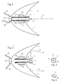
- Figures 1 and 2 illustrate an inventive headlamp which includes a reflector 1 and a light source 2.
- the light source is operative to emit both visible light and ultra-violet light.
- the light source is a suitable discharge type source of known kind.
- the reflector 1 and the light source 2 are intended to transmit simultaneously a light lobe which corresponds to a dipped-beam lobe and a full-beam lobe.
- a filter 4 which is intended to filter-out visible light, but which is transparent to ultra-violet light.
- the filter 4 is displaceably mounted, so as to be movable from a first position, illustrated in Figure 1, in which the filter is located outside the beam path for transmission of said light lobe, to a second position, shown in Figure 2, in which the filter is located in the beam path of at least that part of said light lobe which constitutes the difference between the full-beam lobe and the dipped-beam lobe.
- the filter 4 comprises a fully cylindrical, or partly cylindrical device 7 which can be displaced in a manner to fully or partially surround the light source when occupying said second position, as illustrated in Figure 2.
- Figure 3 shows the cylindrical device from the right in Figure 2.
- the cylindrical device 7 includes two parts, of which one part 8 constitutes a filter and the remaining part 9 comprises a material which is transparent to both visible and ultra-violet light.
- the two cylinder parts 8,9 are given mutually different sizes which depend on the configuration of the reflector and the position of the light source in relation to said reflector, and which also depend on in which part of the total light lobe filtered light is desired.
- the whole of the cylindrical part 4 may comprise a filter operative to filter-out visible light, in which case the headlamp will emit solely ultra-violet light when the filter is located in its second position.
- the cylinder part 8 intended to filter-out ultra-violet light preferably comprises Woods glass.
- the other cylindrical part 9 preferably comprises a glass or plastics material which is transparent to both ultra-violet light and visible light.
- the longitudinal axis of the cylindrical part coincides substantially with the optical axis 11 of the headlamp.
- the filter is attached to a device 12 at the end of the filter remote from the headlamp opening 3, the device 12 being operative to displace the filter along its longitudinal axis between said two positions.
- the filter-displacing device has the form of a draw magnet device 13 of some suitable kind which comprises a coil and a draw rod 14, with the filter connected to the draw rod.
- the draw rod 14 preferably has the form of a tube through which a light-source attachment 15 extends.
- the attachment 15 is illustrated purely schematically by broken lines in Figures 1 and 2, since the attachment itself can have any suitable configuration without detriment to the present invention.
- a spring 16 will preferably be mounted between the draw rod 14 and the magnet 13, this spring 16 being operative to displace the filter to its aforesaid first position, whereas the draw magnet displaces the filter to its aforesaid second position.
- the reference numeral 17 identifies electrical conductors through which current is delivered to the draw magnet.
- the reference numeral 18 indicates conductors through which current is delivered to the light source.
- the present invention operates in the following manner.
- the driver desires a full-beam picture for visible light
- he manipulates a switch which activates current supply to the draw magnet, therewith causing the filter to be moved to its aforesaid first position.
- This manouver results in a full-beam picture for both visible light and ultra-violet light.
- the switch When the driver meets an oncoming vehicle, or when the driver wishes to dip his headlamps for some other reasons, the switch is manipulated in a manner to cause current to be supplied to the draw magnet, such that the filter is displaced from its first position to its second position.
- the filter occupies its second position, the visible light is changed from a full-beam lobe picture to a dipped-beam lobe picture, whereas the ultra-violet light continues to illuminate in accordance with a full-beam lobe.
- the filter prefferably occupy its aforesaid second position in the absence of current supply to the magnet, so that visible light will illuminate in accordance with a dipped-beam lobe in the event of a malfunction in the current supply which prevents current from being delivered to the draw magnet.
- the present invention thus solves the problem discussed in the introduction.
- the invention enables changes to be made rapidly between different visible-light beam patterns, while retaining ultra-violet light in accordance with a full-beam lobe.
- the filter displacing device can have a form different to that described here.
- the filter may be given a different form capable of being adapted to the configuration of the light source used.
- a material other than Woods glass can be used to filter-out visible light and permit ultra-violet light to pass through.
Landscapes
- Engineering & Computer Science (AREA)
- General Engineering & Computer Science (AREA)
- Physics & Mathematics (AREA)
- Spectroscopy & Molecular Physics (AREA)
- Mechanical Engineering (AREA)
- Non-Portable Lighting Devices Or Systems Thereof (AREA)
- Lighting Device Outwards From Vehicle And Optical Signal (AREA)
Claims (6)
- Abblendbarer Fahrzeugscheinwerfer, insbesondere Autoscheinwerfer, der so arbeitet, daß er ultraviolettes und sichtbares Licht abgibt, und der eine Lichtquelle aufweist, die dazu gedacht ist, sichtbares und ultraviolettes Licht abzugeben, der einen Reflektor und einen Filter aufweist, wobei der Filter (4) dafür vorgesehen ist, sichtbares Licht auszufiltern, ultraviolettes Licht jedoch durchzulassen, und wobei der Filter für eine Bewegung aus einer ersten Stellung (Fig. 1), in der der Filter (4) außerhalb des Strahlenweges zum Durchlassen der Lichtkeule angeordnet ist in eine zweite Stellung (Fig. 2), in der der Filter (4) im Strahlenweg angeordnet ist, befestigt ist dadurch gekennzeichnet, daß der Reflektor (1) und die Lichtquelle (2) dafür vorgesehen sind, gleichzeitig einen Lichtkegel zu übertragen, der mit einer Keule eines abgeblendeten Strahles und einer Keule eines vollen Strahles korrespondiert, und daß der Filter (4) in seiner zweiten Stellung im Strahlenweg für den Teil der Lichtkeule, der den Unterschied zwischen der Vollstrahlkeule und der Keule des abgeblendeten Strahles bestimmt, angeordnet ist, wobei, wenn der Filter (4) in der zweiten Stellung angeordnet ist, nur ultraviolettes Licht in dem Teil der übertragenen Lichtkeule, der den genannten Unterschied ausmacht, übertragen wird, wobei sichtbares Licht und ultraviolettes Licht in dem Teil der Lichtkeule durchgelassen wird, der mit einer Keule mit abgeblendetem Strahl korrespondiert.
- Abblendbarer Scheinwerfer nach Anspruch 1, dadurch gekennzeichnet, daß der Filter (4) eine vollzylindrische oder teilweise zylindrische Einrichtung (7) aufweist, die verschoben werden kann, um die Lichtquelle (2) in der zweiten Stellung teilweise zu umgeben.
- Abblendbarer Scheinwerfer nach Anspruch 1 oder 2, dadurch gekennzeichnet, daß die Längsachse der zylindrischen Einrichtung (7) mit der optischen Achse (11) des Scheinwerfers zusammenfällt, und daß der Filter (4) an seinem von der Scheinwerferöffnung (3) entfernten Ende mit einer Einrichtung (12) verbunden ist, die wirksam ist, den Filter (4) entlang seiner Längsachse zwischen den beiden Stellungen zu verschieben.
- Abblendbarer Scheinwerfer nach Anspruch 1, 2 oder 3, dadurch gekennzeichnet, daß ein Teil (8) der zylindrischen Einrichtung (7) einen Filter (4) aufweist, und daß der verbleibende Teil (9) der zylindrischen Einrichtung (7) ein Material aufweist, das für sichtbares und ultraviolettes Licht transparent ist.
- Abblendbarer Scheinwerfer nach Anspruch 1, 2, 3 oder 4, dadurch gekennzeichnet, daß die Filterverschiebeeinrichtung (12) einen Zugmagneten (13) umfaßt, der eine Wicklung und eine Zugstange (14) aufweist, und daß die zylindrische Einrichtung (7) mit der Zugstange (14) verbunden ist.
- Abblendbarer Scheinwerfer nach Anspruch 1, 2, 3, 4 oder 5, dadurch gekennzeichnet, daß die Zugstange (14) ein Rohr aufweist, durch das sich eine Lichtquellenbefestigung (15) erstreckt.
Applications Claiming Priority (3)
| Application Number | Priority Date | Filing Date | Title |
|---|---|---|---|
| SE8900250A SE466251B (sv) | 1989-01-24 | 1989-01-24 | Avblaendningsbar straalkastare foer fordon |
| SE8900250 | 1989-01-24 | ||
| PCT/SE1990/000017 WO1990008673A1 (en) | 1989-01-24 | 1990-01-10 | Dippable headlamps |
Publications (2)
| Publication Number | Publication Date |
|---|---|
| EP0408717A1 EP0408717A1 (de) | 1991-01-23 |
| EP0408717B1 true EP0408717B1 (de) | 1995-04-05 |
Family
ID=20374842
Family Applications (1)
| Application Number | Title | Priority Date | Filing Date |
|---|---|---|---|
| EP90902414A Expired - Lifetime EP0408717B1 (de) | 1989-01-24 | 1990-01-10 | Scheinwerfer mit abblendlichtstellung |
Country Status (9)
| Country | Link |
|---|---|
| US (1) | US5029050A (de) |
| EP (1) | EP0408717B1 (de) |
| JP (1) | JP2761434B2 (de) |
| AT (1) | ATE120697T1 (de) |
| BR (1) | BR9004919A (de) |
| DE (1) | DE69018330T2 (de) |
| ES (1) | ES2070314T3 (de) |
| SE (1) | SE466251B (de) |
| WO (1) | WO1990008673A1 (de) |
Families Citing this family (12)
| Publication number | Priority date | Publication date | Assignee | Title |
|---|---|---|---|---|
| DE3932216C3 (de) * | 1989-09-27 | 2002-09-12 | Bosch Gmbh Robert | Beleuchtungseinrichtung für Fahrzeuge |
| SE464454B (sv) * | 1990-04-27 | 1991-04-29 | Ultralux Ab | Anordning vid straalkastare foer fordon |
| FR2664363B1 (fr) * | 1990-07-03 | 1992-12-31 | Valeo Vision | Projecteur a plusieurs fonctions, en particulier pour vehicule automobile, adapte a ameliorer l'eclairement d'elements de signalisation routiere. |
| DE4202872A1 (de) * | 1992-02-01 | 1993-08-05 | Bosch Gmbh Robert | Scheinwerfer fuer kraftfahrzeuge |
| JP3163569B2 (ja) * | 1992-02-18 | 2001-05-08 | 株式会社小糸製作所 | 自動車用ヘッドランプ |
| US5323301A (en) * | 1992-12-08 | 1994-06-21 | Robert Kaufman | Dimmable studio lighting device |
| EP0634306B1 (de) * | 1993-07-16 | 1997-04-09 | Hamamatsu Photonics K.K. | Lichtbestrahlungseinrichtung |
| US5528475A (en) * | 1993-12-24 | 1996-06-18 | Koito Manufacturing Co., Ltd. | Control circuit for automobile headlamps emitting light in variable color |
| DE10044392B4 (de) * | 2000-09-08 | 2018-10-04 | Automotive Lighting Reutlingen Gmbh | Fahrzeugscheinwerfer |
| DE10121480A1 (de) * | 2001-05-03 | 2002-11-14 | Bosch Gmbh Robert | Verstelleinrichtung und Verfahren zum Umschalten eines Kraftfahrzeugscheinwerfers |
| US6866407B2 (en) * | 2002-12-17 | 2005-03-15 | Cpikorea Ltd. | Vehicle headlight |
| US7101067B2 (en) * | 2004-07-09 | 2006-09-05 | Decoma International Inc. | Dual beam high intensity discharge reflector |
Family Cites Families (7)
| Publication number | Priority date | Publication date | Assignee | Title |
|---|---|---|---|---|
| DE483263C (de) * | 1924-07-01 | 1929-10-02 | Karl Dumas Chambers | Verfahren und Vorrichtung zur Verhinderung der Scheinwerferblendung, insbesondere bei sich entgegenkommenden Fahrzeugen |
| DE449776C (de) * | 1926-02-17 | 1927-09-23 | Emil Hildenbrand | Fahrtrichtungsanzeiger |
| US2343518A (en) * | 1941-09-15 | 1944-03-07 | John D Rippey | Electric lighting device |
| DE2249930A1 (de) * | 1972-10-12 | 1974-04-18 | Klitzing Von Michael | Vorrichtung zum beleuchten der fahrstrecke eines fahrzeugs durch blendungsfreien uv-scheinwerfer |
| JPS6217904A (ja) * | 1985-07-15 | 1987-01-26 | 双葉電子工業株式会社 | 光源 |
| SE458594B (sv) * | 1987-10-22 | 1989-04-17 | Labino Patent Ab | Straalkastare foer fordon |
| US4951178A (en) * | 1988-10-05 | 1990-08-21 | Koito Manfacturing Co., Ltd. | Headlight for motor vehicle |
-
1989
- 1989-01-24 SE SE8900250A patent/SE466251B/sv not_active IP Right Cessation
-
1990
- 1990-01-10 AT AT90902414T patent/ATE120697T1/de not_active IP Right Cessation
- 1990-01-10 EP EP90902414A patent/EP0408717B1/de not_active Expired - Lifetime
- 1990-01-10 DE DE69018330T patent/DE69018330T2/de not_active Expired - Fee Related
- 1990-01-10 JP JP2502396A patent/JP2761434B2/ja not_active Expired - Lifetime
- 1990-01-10 ES ES90902414T patent/ES2070314T3/es not_active Expired - Lifetime
- 1990-01-10 US US07/573,146 patent/US5029050A/en not_active Expired - Fee Related
- 1990-01-10 WO PCT/SE1990/000017 patent/WO1990008673A1/en not_active Ceased
- 1990-01-10 BR BR909004919A patent/BR9004919A/pt not_active IP Right Cessation
Non-Patent Citations (1)
| Title |
|---|
| Bilstralkastare Provas Med 1jus Som Varken Syns Eller Blandar", see page 6 * |
Also Published As
| Publication number | Publication date |
|---|---|
| SE8900250D0 (sv) | 1989-01-24 |
| SE466251B (sv) | 1992-01-20 |
| DE69018330T2 (de) | 1995-08-31 |
| ES2070314T3 (es) | 1995-06-01 |
| SE8900250L (sv) | 1990-07-25 |
| WO1990008673A1 (en) | 1990-08-09 |
| ATE120697T1 (de) | 1995-04-15 |
| EP0408717A1 (de) | 1991-01-23 |
| JPH03503585A (ja) | 1991-08-08 |
| US5029050A (en) | 1991-07-02 |
| JP2761434B2 (ja) | 1998-06-04 |
| BR9004919A (pt) | 1991-07-30 |
| DE69018330D1 (de) | 1995-05-11 |
Similar Documents
| Publication | Publication Date | Title |
|---|---|---|
| US4970628A (en) | Headlamp for automotive vehicles | |
| EP0408717B1 (de) | Scheinwerfer mit abblendlichtstellung | |
| US20120140503A1 (en) | Head Lamp for Vehicle | |
| JP2003260975A (ja) | 自動車のための前照システム | |
| CN104470756A (zh) | 具有可控光源和发光强度的车辆的多功能光学单元 | |
| EP1801848A3 (de) | Mehrfaden-Kfz-Scheinwerfer-Lampe | |
| JP2010086961A (ja) | 自動車用の適応型照明装置 | |
| JP4404626B2 (ja) | 車両用灯具 | |
| JP2009012553A (ja) | 車両用灯具 | |
| GB2192449A (en) | Headlight | |
| US6955439B2 (en) | Dual filament static bending lamp | |
| WO1987006325A1 (en) | Head lamp, in particular headlight for cars, provided with several filaments adapted to emit beams of white and/or coloured light to be used as sealed beam light and foglight | |
| GR3020967T3 (en) | Front section of a motor vehicle with fog lighting | |
| WO2022125030A1 (en) | Homogeneous lighting of complex functional areas | |
| EP0805763B1 (de) | Verfahren und einrichtung zur steuerung eines fahrzeugscheinwerfers | |
| EP2010413B1 (de) | Kraftfahrzeugscheinwerfer | |
| CN114251624A (zh) | 机动车前照灯的产生具有指示光的基本光分布的照明设备 | |
| KR100350633B1 (ko) | 차량의 아웃사이드 미러에 운행정보제공을 위한 표시장치 | |
| WO2024195816A1 (ja) | 車輌用灯具 | |
| GB2346955A (en) | Polarising headlights | |
| JP2002140904A (ja) | 2灯式照明装置 | |
| GB2093579A (en) | A headlight unit | |
| KR19990033301A (ko) | 자동차 헤드 램프 | |
| KR19980038089A (ko) | 차량의 헤드램프용 주사빔 전환장치 | |
| JPH07134902A (ja) | 灯色切替装置 |
Legal Events
| Date | Code | Title | Description |
|---|---|---|---|
| PUAI | Public reference made under article 153(3) epc to a published international application that has entered the european phase |
Free format text: ORIGINAL CODE: 0009012 |
|
| AK | Designated contracting states |
Kind code of ref document: A1 Designated state(s): AT BE CH DE DK ES FR GB IT LI LU NL SE |
|
| 17P | Request for examination filed |
Effective date: 19910125 |
|
| RAP1 | Party data changed (applicant data changed or rights of an application transferred) |
Owner name: ULTRALUX AB |
|
| 17Q | First examination report despatched |
Effective date: 19930507 |
|
| GRAA | (expected) grant |
Free format text: ORIGINAL CODE: 0009210 |
|
| AK | Designated contracting states |
Kind code of ref document: B1 Designated state(s): AT BE CH DE DK ES FR GB IT LI LU NL SE |
|
| PG25 | Lapsed in a contracting state [announced via postgrant information from national office to epo] |
Ref country code: NL Free format text: LAPSE BECAUSE OF FAILURE TO SUBMIT A TRANSLATION OF THE DESCRIPTION OR TO PAY THE FEE WITHIN THE PRESCRIBED TIME-LIMIT Effective date: 19950405 Ref country code: LI Effective date: 19950405 Ref country code: DK Effective date: 19950405 Ref country code: CH Effective date: 19950405 Ref country code: BE Effective date: 19950405 Ref country code: AT Effective date: 19950405 |
|
| REF | Corresponds to: |
Ref document number: 120697 Country of ref document: AT Date of ref document: 19950415 Kind code of ref document: T |
|
| ET | Fr: translation filed | ||
| REF | Corresponds to: |
Ref document number: 69018330 Country of ref document: DE Date of ref document: 19950511 |
|
| ITF | It: translation for a ep patent filed | ||
| REG | Reference to a national code |
Ref country code: ES Ref legal event code: FG2A Ref document number: 2070314 Country of ref document: ES Kind code of ref document: T3 |
|
| PG25 | Lapsed in a contracting state [announced via postgrant information from national office to epo] |
Ref country code: SE Effective date: 19950705 |
|
| REG | Reference to a national code |
Ref country code: CH Ref legal event code: PL |
|
| NLV1 | Nl: lapsed or annulled due to failure to fulfill the requirements of art. 29p and 29m of the patents act | ||
| PG25 | Lapsed in a contracting state [announced via postgrant information from national office to epo] |
Ref country code: LU Free format text: LAPSE BECAUSE OF NON-PAYMENT OF DUE FEES Effective date: 19960131 |
|
| PLBE | No opposition filed within time limit |
Free format text: ORIGINAL CODE: 0009261 |
|
| STAA | Information on the status of an ep patent application or granted ep patent |
Free format text: STATUS: NO OPPOSITION FILED WITHIN TIME LIMIT |
|
| 26N | No opposition filed | ||
| PGFP | Annual fee paid to national office [announced via postgrant information from national office to epo] |
Ref country code: GB Payment date: 19991210 Year of fee payment: 11 |
|
| PGFP | Annual fee paid to national office [announced via postgrant information from national office to epo] |
Ref country code: FR Payment date: 19991223 Year of fee payment: 11 |
|
| PGFP | Annual fee paid to national office [announced via postgrant information from national office to epo] |
Ref country code: ES Payment date: 20000111 Year of fee payment: 11 |
|
| PGFP | Annual fee paid to national office [announced via postgrant information from national office to epo] |
Ref country code: DE Payment date: 20000113 Year of fee payment: 11 |
|
| PG25 | Lapsed in a contracting state [announced via postgrant information from national office to epo] |
Ref country code: GB Free format text: LAPSE BECAUSE OF NON-PAYMENT OF DUE FEES Effective date: 20010110 |
|
| PG25 | Lapsed in a contracting state [announced via postgrant information from national office to epo] |
Ref country code: ES Free format text: LAPSE BECAUSE OF NON-PAYMENT OF DUE FEES Effective date: 20010111 |
|
| GBPC | Gb: european patent ceased through non-payment of renewal fee |
Effective date: 20010110 |
|
| PG25 | Lapsed in a contracting state [announced via postgrant information from national office to epo] |
Ref country code: FR Free format text: LAPSE BECAUSE OF NON-PAYMENT OF DUE FEES Effective date: 20010928 |
|
| PG25 | Lapsed in a contracting state [announced via postgrant information from national office to epo] |
Ref country code: DE Free format text: LAPSE BECAUSE OF NON-PAYMENT OF DUE FEES Effective date: 20011101 |
|
| REG | Reference to a national code |
Ref country code: FR Ref legal event code: ST |
|
| REG | Reference to a national code |
Ref country code: ES Ref legal event code: FD2A Effective date: 20020916 |
|
| PG25 | Lapsed in a contracting state [announced via postgrant information from national office to epo] |
Ref country code: IT Free format text: LAPSE BECAUSE OF NON-PAYMENT OF DUE FEES;WARNING: LAPSES OF ITALIAN PATENTS WITH EFFECTIVE DATE BEFORE 2007 MAY HAVE OCCURRED AT ANY TIME BEFORE 2007. THE CORRECT EFFECTIVE DATE MAY BE DIFFERENT FROM THE ONE RECORDED. Effective date: 20050110 |