EP0805763B1 - Verfahren und einrichtung zur steuerung eines fahrzeugscheinwerfers - Google Patents
Verfahren und einrichtung zur steuerung eines fahrzeugscheinwerfers Download PDFInfo
- Publication number
- EP0805763B1 EP0805763B1 EP96901165A EP96901165A EP0805763B1 EP 0805763 B1 EP0805763 B1 EP 0805763B1 EP 96901165 A EP96901165 A EP 96901165A EP 96901165 A EP96901165 A EP 96901165A EP 0805763 B1 EP0805763 B1 EP 0805763B1
- Authority
- EP
- European Patent Office
- Prior art keywords
- power
- full
- light source
- beam lighting
- switch
- Prior art date
- Legal status (The legal status is an assumption and is not a legal conclusion. Google has not performed a legal analysis and makes no representation as to the accuracy of the status listed.)
- Expired - Lifetime
Links
Images
Classifications
-
- B—PERFORMING OPERATIONS; TRANSPORTING
- B60—VEHICLES IN GENERAL
- B60Q—ARRANGEMENT OF SIGNALLING OR LIGHTING DEVICES, THE MOUNTING OR SUPPORTING THEREOF OR CIRCUITS THEREFOR, FOR VEHICLES IN GENERAL
- B60Q1/00—Arrangement of optical signalling or lighting devices, the mounting or supporting thereof or circuits therefor
- B60Q1/02—Arrangement of optical signalling or lighting devices, the mounting or supporting thereof or circuits therefor the devices being primarily intended to illuminate the way ahead or to illuminate other areas of way or environments
- B60Q1/04—Arrangement of optical signalling or lighting devices, the mounting or supporting thereof or circuits therefor the devices being primarily intended to illuminate the way ahead or to illuminate other areas of way or environments the devices being headlights
- B60Q1/14—Arrangement of optical signalling or lighting devices, the mounting or supporting thereof or circuits therefor the devices being primarily intended to illuminate the way ahead or to illuminate other areas of way or environments the devices being headlights having dimming means
- B60Q1/1446—Arrangement of optical signalling or lighting devices, the mounting or supporting thereof or circuits therefor the devices being primarily intended to illuminate the way ahead or to illuminate other areas of way or environments the devices being headlights having dimming means controlled by mechanically actuated switches
- B60Q1/1453—Hand actuated switches
- B60Q1/1461—Multifunction switches for dimming headlights and controlling additional devices, e.g. for controlling direction indicating lights
-
- B—PERFORMING OPERATIONS; TRANSPORTING
- B60—VEHICLES IN GENERAL
- B60Q—ARRANGEMENT OF SIGNALLING OR LIGHTING DEVICES, THE MOUNTING OR SUPPORTING THEREOF OR CIRCUITS THEREFOR, FOR VEHICLES IN GENERAL
- B60Q1/00—Arrangement of optical signalling or lighting devices, the mounting or supporting thereof or circuits therefor
- B60Q1/02—Arrangement of optical signalling or lighting devices, the mounting or supporting thereof or circuits therefor the devices being primarily intended to illuminate the way ahead or to illuminate other areas of way or environments
- B60Q1/04—Arrangement of optical signalling or lighting devices, the mounting or supporting thereof or circuits therefor the devices being primarily intended to illuminate the way ahead or to illuminate other areas of way or environments the devices being headlights
- B60Q1/14—Arrangement of optical signalling or lighting devices, the mounting or supporting thereof or circuits therefor the devices being primarily intended to illuminate the way ahead or to illuminate other areas of way or environments the devices being headlights having dimming means
- B60Q1/1415—Dimming circuits
-
- B—PERFORMING OPERATIONS; TRANSPORTING
- B60—VEHICLES IN GENERAL
- B60Q—ARRANGEMENT OF SIGNALLING OR LIGHTING DEVICES, THE MOUNTING OR SUPPORTING THEREOF OR CIRCUITS THEREFOR, FOR VEHICLES IN GENERAL
- B60Q1/00—Arrangement of optical signalling or lighting devices, the mounting or supporting thereof or circuits therefor
- B60Q1/02—Arrangement of optical signalling or lighting devices, the mounting or supporting thereof or circuits therefor the devices being primarily intended to illuminate the way ahead or to illuminate other areas of way or environments
- B60Q1/04—Arrangement of optical signalling or lighting devices, the mounting or supporting thereof or circuits therefor the devices being primarily intended to illuminate the way ahead or to illuminate other areas of way or environments the devices being headlights
- B60Q1/06—Arrangement of optical signalling or lighting devices, the mounting or supporting thereof or circuits therefor the devices being primarily intended to illuminate the way ahead or to illuminate other areas of way or environments the devices being headlights adjustable, e.g. remotely-controlled from inside vehicle
- B60Q1/076—Arrangement of optical signalling or lighting devices, the mounting or supporting thereof or circuits therefor the devices being primarily intended to illuminate the way ahead or to illuminate other areas of way or environments the devices being headlights adjustable, e.g. remotely-controlled from inside vehicle by electrical means including means to transmit the movements, e.g. shafts or joints
-
- B—PERFORMING OPERATIONS; TRANSPORTING
- B60—VEHICLES IN GENERAL
- B60Q—ARRANGEMENT OF SIGNALLING OR LIGHTING DEVICES, THE MOUNTING OR SUPPORTING THEREOF OR CIRCUITS THEREFOR, FOR VEHICLES IN GENERAL
- B60Q1/00—Arrangement of optical signalling or lighting devices, the mounting or supporting thereof or circuits therefor
- B60Q1/02—Arrangement of optical signalling or lighting devices, the mounting or supporting thereof or circuits therefor the devices being primarily intended to illuminate the way ahead or to illuminate other areas of way or environments
- B60Q1/04—Arrangement of optical signalling or lighting devices, the mounting or supporting thereof or circuits therefor the devices being primarily intended to illuminate the way ahead or to illuminate other areas of way or environments the devices being headlights
- B60Q1/06—Arrangement of optical signalling or lighting devices, the mounting or supporting thereof or circuits therefor the devices being primarily intended to illuminate the way ahead or to illuminate other areas of way or environments the devices being headlights adjustable, e.g. remotely-controlled from inside vehicle
- B60Q1/08—Arrangement of optical signalling or lighting devices, the mounting or supporting thereof or circuits therefor the devices being primarily intended to illuminate the way ahead or to illuminate other areas of way or environments the devices being headlights adjustable, e.g. remotely-controlled from inside vehicle automatically
Definitions
- the present invention relates to a method and to an arrangement for controlling the headlights of automotive vehicles, and then in particular car headlights.
- a more powerful bulb has the drawback of necessitating the driver to dip the lights earlier when driving in the dark on a typically trafficated road with repeated encounters with oncoming traffic interspersed with a clear road ahead, so as not to dazzle the drivers of oncoming traffic, as opposed to the case when using a standard bulb.
- This drawback is the reason why drivers do not normally have extra lights, such as long-distance lighting, switched-on when driving along roads in which oncoming vehicles are frequently encountered, therewith requiring the lights to be dipped repeatedly.
- This problem is solved in accordance with the present invention by providing weak headlights for certain situations while eliminating the aforesaid drawback and, at the same time, eliminating the need of extra lighting.
- DE 34 36 391 shows to regulate the luminous flux from the left or the right headlight by a respective resistor in order to avoid that the driver of an oncoming vehicle shall be dazzled.
- US 5,382,877 shows a lamp system which includes a current limiting resistor to limit the intensity of illumination.
- the purpose relates to problems arising at white nights and fog, where the solution is to control the ordinary headlamps to give a low intensity.
- the present invention thus relates to a method of controlling the full-beam headlights of automotive vehicles, particularly cars, whose headlights are provided with dischargeable light sources, where the power supplied to the light source is controlled by a switch, and is characterized by choosing the light source so that when supplying said light source with its nominal power it will produce a luminous flux which greatly exceeds a luminous flux normal for full-beam lighting; by supplying the light source with a lower power such as to cause the light source to produce a luminous flux which is normal for full-beam lighting; and by providing means for enabling the light source to be supplied selectively with said lower power or with its nominal power, which switch includes a driver-operated switch by means of which switching of said means is effected such that in a first position of the switch the driver when switching between full-beam lighting and dipped-beam lighting alternates between dipped-beam lighting having a predetermined luminous flux and full-beam lighting having the lower power, and in another position of the switch alternates between said dipped
- the invention also relates to an arrangement of the kind having the main characteristic features set forth in Claim 5.
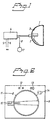
- Figure 1 illustrates an arrangement for controlling the full beam headlights of automotive vehicles, particularly cars, wherein headlights 1 are provided with light sources 2 of a dischargeable kind.
- the reference numeral 3 in Figure 1 identifies the headlight reflector.
- Such light sources are available commercially and marketed, among others, by PHILIPS under the trade name Micro Power-Light.
- Such light sources 2 are powered by a power means 4 which applies an alternating voltage across the light source.
- the voltage applied is normally a square-wave voltage.
- Such power means are also known and available commercially.
- the power means 4 When applied to a car or to some other automotive vehicle, the power means 4 is connected to the vehicle electrical system by cables 5, 6 which supply the power means with direct current voltage.
- the light source 2 is designed to produce a luminous flux which greatly exceeds the normal luminous flux of full-beam lighting when supplied with its nominal power.
- the power means 4 is designed to supply the light source 2 with lower power when in a first position such as to emit from the headlight 1 a full beam having a luminous flux which is normal for a full beam. Also provided is a means 7 with which the power means 4 can be switched selectively from said first position to a second position in which the power means will supply the light source 2 with its nominal power.
- this lower power is between 40% and 70% of the nominal or rated power, preferably about 50%.
- a full beam will normally have a luminous flux of 1,500 lumens for instance. This means that a preferred embodiment of the light source will generate a luminous flux of 3,000 lumens at nominal power.
- a discharge lamp of the aforesaid kind having a nominal power of 35 Watts.
- this light source will produce a luminous flux of 3,000 lumens when supplied with its nominal power.
- the light source When supplied with a power of 18 Watts, the light source will produce a luminous flux of 1,500 lumens.
- the means 7 includes a driver-operated switch, by means of which the power means can be switched between two said positions.
- the switch is connected by means of a cable 8 to an appropriate known control circuit which is conveniently integrated with the power means and which functions to control the power output of said power means by voltage-regulating the output voltage and/or output current of the power means.
- the beam When the driver alternates between full beam and dipped beam in a normal manner, the beam will be switched between dipped lighting with a predetermined luminous flux given by the light source for dipped lighting and a full beam with the lower power input when the switch is in its first position, i.e. a full beam with normal luminous flux.
- the switch When the switch is in its second position, the vehicle lighting will be switched between said dipped lighting and a full beam lighting having the higher power input, i.e. lighting which corresponds to full-beam lighting in combination with long-distance lighting.
- This embodiment can be applied irrespective of whether the dipped-beam headlights and the full-beam headlights are mutually separate or integrated in one and the same headlamp unit.
- the switch may be an integral part of the normal light switch in a car or some other automotive vehicle.
- Figure 2 illustrates an example of one such light switch 9.
- the reference numeral 10 identifies automatic activation of the vehicle lights when the vehicle is started, for instance activation of the vehicle side lights and dipped/full beam lighting. All lights are switched off in position 11. A position light or the like is ignited in position 12.
- Normal dipped lighting and normal full-beam lighting are activated in position 13. This enables the power means to drive the light source 2 at the lower power input.
- the driver alternates between dipped beam and full beam with the standard full beam switch, normally a lever placed on the steering wheel.
- Standard dipped lighting with the stronger full-beam lighting is activated in position 14. This enables the power means to drive the light source 2 at its nominal power input.
- the driver alternates between dipped lighting and full-beam lighting with the aid of the standard full-beam switch.
- the present invention obviates the need to fit extra lighting to the vehicle while still obtaining, when desired, the quality of light that an extra light would provide.
Landscapes
- Engineering & Computer Science (AREA)
- Mechanical Engineering (AREA)
- Lighting Device Outwards From Vehicle And Optical Signal (AREA)
Claims (5)
- Verfahren zum Steuern der Fahrlicht-Scheinwerfer von Kraftfahrzeugen, insbesondere von Personenkraftwagen, deren Scheinwerfer mit Entladungs-Lichtquellen versehen sind, wobei die der Lichtquelle zugeführte Leistung durch einen Schalter gesteuert wird, gekennzeichnet durch Wählen der Lichtquelle (2) so, daß, wenn die Lichtquelle mit ihrer Nominalleistung versorgt wird, sie einen Lichtstrom erzeugt, der einen für das Fahrlicht normalen Lichtstrom wesentlich übersteigt; durch Versorgen der Lichtquelle (2) mit einer niedrigeren Leistung derart, daß die Lichtquelle (2) veranlaßt wird, einen Lichtstrom zu erzeugen, der für das Fahrlicht normal ist; und durch das Bereitstellen von Einrichtungen (7; 10, 4), die es der Lichtquelle (2) ermöglichen, selektiv mit der niedrigeren Leistung oder mit ihrer Nominalleistung versorgt zu werden, wobei die Schalteinrichtung einen von einem Fahrer betätigten Schalter (7; 10) aufweist, durch den das Schalten der Einrichtung bewirkt wird, so daß in einer ersten Schaltung des Schalters (7; 10) der Fahrer, wenn er zwischen dem Fahrlicht und dem Abblendlicht schaltet, zwischen einem Abblendlicht mit einem vorbestimmten Lichtstrom und einem Fahrlicht mit der geringeren Leistung alterniert, und in einer anderen Stellung des Schalters (7; 10) zwischen dem Abblendlicht und dem Fahrlicht mit der höheren Leistung alterniert.
- Verfahren nach Anspruch 1, dadurch gekennzeichnet, daß die geringere Leistung zwischen 40% und 70% der Nominalleistung, vorzugsweise etwa 50%, ist
- Verfahren nach Anspruch 1 oder 2, dadurch gekennzeichnet, daß die Einrichtung (7; 10) veranlaßt wird, eine Leistungseinrichtung (4) für die Lichtquelle so einzustellen, daß sie die Lichtquelle mit einem der beiden Leistungszustände versorgt.
- Anordnung zum Steuern der Fahrlicht-Scheinwerfer von Kraftfahrzeugen, insbesondere von Personenkraftwagen, wobei die Scheinwerfer mit Entladungs-Lichtquellen versehen sind, die durch eine Leistungseinrichtung versorgt werden, die eine alternierende Spannung auf die Lichtquelle aufbringt, wobei die der Lichtquelle zugeführte Leistung durch einen Schalter gesteuert wird, dadurch gekennzeichnet, daß, wenn sie mit ihrer Nominalleistung versorgt wird, die Lichtquelle (2) so funktioniert, daß sie einen Lichtstrom erzeugt, der den normalen Lichtstrom des Fahrlichts wesentlich übersteigt; daß die Leistungseinrichtung (4) so konstruiert ist, daß, wenn sie sich in einem Zustand befindet, sie die Lichtquelle (2) mit einer geringeren Leistung versorgt, so daß der Scheinwerfer ein Fahrlicht mit einem Lichtstrom aussendet, der für das Fahrlicht normal ist; und daß die Anordnung eine Einrichtung (7; 10) zum selektiven Schalten der Leistungseinrichtung (4) von dem einen Zustand in einen anderen Zustand aufweist, in welchem anderen Zustand die Leistungseinrichtung (4) die Lichtquelle (2) mit ihrer Nominalleistung versorgt, daß der Schalter einen von einem Fahrer betätigten Schalter (7; 10) aufweist, durch den das Schalten der Einrichtung bewirkt wird, so daß in einer ersten Stellung des Schalters (7; 10) der Fahrer, wenn er zwischen Fahrlicht und Abblendlicht schaltet, zwischen Abblendlicht mit einem vorbestimmten Lichtstrom und Fahrlicht mit der geringeren Leistung alterniert, und so daß, wenn sich der Schalter (7; 10) in seiner zweiten Stellung befindet, der Fahrer zwischen dem Abblendlicht und einem Fahrlicht mit der höheren Leistung alterniert.
- Anordnung nach Ansprucn 4, dadurch gekennzeichnet, daß die geringere Leistung zwischen 40% und 70% der Nominalleistung, vorzugsweise 50%, ist.
Applications Claiming Priority (3)
| Application Number | Priority Date | Filing Date | Title |
|---|---|---|---|
| SE9500125A SE503989C2 (sv) | 1995-01-16 | 1995-01-16 | Förfarande och anordning för att reglera strålkastare för fordon |
| SE9500125 | 1995-01-16 | ||
| PCT/SE1996/000023 WO1996022194A1 (en) | 1995-01-16 | 1996-01-12 | A method and arrangement for controlling the headlights of automotive vehicles |
Publications (2)
| Publication Number | Publication Date |
|---|---|
| EP0805763A1 EP0805763A1 (de) | 1997-11-12 |
| EP0805763B1 true EP0805763B1 (de) | 2001-09-05 |
Family
ID=20396831
Family Applications (1)
| Application Number | Title | Priority Date | Filing Date |
|---|---|---|---|
| EP96901165A Expired - Lifetime EP0805763B1 (de) | 1995-01-16 | 1996-01-12 | Verfahren und einrichtung zur steuerung eines fahrzeugscheinwerfers |
Country Status (8)
| Country | Link |
|---|---|
| US (1) | US5900698A (de) |
| EP (1) | EP0805763B1 (de) |
| JP (1) | JPH10512209A (de) |
| KR (1) | KR19980701407A (de) |
| AU (1) | AU4498996A (de) |
| DE (1) | DE69614999T2 (de) |
| SE (1) | SE503989C2 (de) |
| WO (1) | WO1996022194A1 (de) |
Families Citing this family (2)
| Publication number | Priority date | Publication date | Assignee | Title |
|---|---|---|---|---|
| JP3878776B2 (ja) | 1999-09-10 | 2007-02-07 | 株式会社小糸製作所 | 車輌用放電灯装置 |
| US6552493B2 (en) * | 2001-08-20 | 2003-04-22 | Kuo-Pin Yen | High-low beam switching device for a headlight |
Family Cites Families (9)
| Publication number | Priority date | Publication date | Assignee | Title |
|---|---|---|---|---|
| US1971341A (en) * | 1930-11-01 | 1934-08-28 | Fred I Getty | Light and signal control for vehicles |
| US1954806A (en) * | 1931-05-23 | 1934-04-17 | Gen Motors Corp | Automobile headlighting system |
| US3621331A (en) * | 1969-01-08 | 1971-11-16 | Cox & Co Inc | Arrangement for igniting and operating gaseous discharge lamps |
| US3617795A (en) * | 1970-03-16 | 1971-11-02 | Sylvania Electric Prod | Automotive headlight system |
| DE3436391A1 (de) * | 1984-06-22 | 1986-01-02 | Herbert 6720 Speyer Kripp | Verfahren zur betaetigung der frontseitigen beleuchtungsanlage eines kraftfahrzeuges und schaltungsanordnung zur durchfuehrung des verfahrens |
| JPH0784154B2 (ja) * | 1989-02-16 | 1995-09-13 | 日産自動車株式会社 | 放電灯の制御装置 |
| JPH0741816B2 (ja) * | 1989-07-03 | 1995-05-10 | 株式会社小糸製作所 | 車輌用前照灯装置 |
| JP2745493B2 (ja) * | 1992-03-19 | 1998-04-28 | 矢崎総業株式会社 | 車両用前照灯制御装置 |
| US5463287A (en) * | 1993-10-06 | 1995-10-31 | Tdk Corporation | Discharge lamp lighting apparatus which can control a lighting process |
-
1995
- 1995-01-16 SE SE9500125A patent/SE503989C2/sv not_active IP Right Cessation
-
1996
- 1996-01-12 EP EP96901165A patent/EP0805763B1/de not_active Expired - Lifetime
- 1996-01-12 JP JP8522193A patent/JPH10512209A/ja active Pending
- 1996-01-12 DE DE69614999T patent/DE69614999T2/de not_active Expired - Lifetime
- 1996-01-12 WO PCT/SE1996/000023 patent/WO1996022194A1/en not_active Ceased
- 1996-01-12 AU AU44989/96A patent/AU4498996A/en not_active Abandoned
- 1996-01-12 KR KR1019970704796A patent/KR19980701407A/ko not_active Ceased
- 1996-01-12 US US08/875,007 patent/US5900698A/en not_active Expired - Lifetime
Also Published As
| Publication number | Publication date |
|---|---|
| KR19980701407A (ko) | 1998-05-15 |
| DE69614999D1 (de) | 2001-10-11 |
| SE9500125L (sv) | 1996-07-17 |
| US5900698A (en) | 1999-05-04 |
| EP0805763A1 (de) | 1997-11-12 |
| JPH10512209A (ja) | 1998-11-24 |
| SE9500125D0 (sv) | 1995-01-16 |
| WO1996022194A1 (en) | 1996-07-25 |
| AU4498996A (en) | 1996-08-07 |
| SE503989C2 (sv) | 1996-10-14 |
| DE69614999T2 (de) | 2002-04-11 |
Similar Documents
| Publication | Publication Date | Title |
|---|---|---|
| US6016035A (en) | Light assembly, preferably tail light assembly, of a vehicle, preferably a motor vehicle | |
| JP4286674B2 (ja) | 車両用灯体制御装置 | |
| JP5199798B2 (ja) | 車両用前照灯装置 | |
| US7959337B2 (en) | Vehicle light and method | |
| CN1175469C (zh) | 白炽灯 | |
| US20070091629A1 (en) | Vehicle Lighting Device | |
| KR0135320B1 (ko) | 색조정이 가능한 자동차용 등화장치 | |
| JP2009012553A (ja) | 車両用灯具 | |
| US5536975A (en) | Device for projecting scanning effects with standard automotive headlamps | |
| EP0805763B1 (de) | Verfahren und einrichtung zur steuerung eines fahrzeugscheinwerfers | |
| JPH1191437A (ja) | 車両用前照灯制御装置 | |
| KR101000183B1 (ko) | 주간 헤드 램프 점등 제어 장치 | |
| JP2019025964A (ja) | 車両用灯具 | |
| KR100581832B1 (ko) | 안개등 연동형 미등이 장착된 차량 | |
| JPH0512107Y2 (de) | ||
| KR920000537Y1 (ko) | 자동차용 전조등 조절회로 | |
| JP2959749B2 (ja) | 車両用ライト制御装置 | |
| KR0116398Y1 (ko) | 자동차의 안개등 | |
| Reif | Lighting technology | |
| JP2013054831A (ja) | 車両用灯具 | |
| JP2004284371A (ja) | 自動車における前照灯の減光装置 | |
| JP2004050876A (ja) | 車両用前照灯 | |
| JPH0367889B2 (de) | ||
| GB2233753A (en) | Angled driving lamps and activating circuit far vehicles | |
| KR20040080195A (ko) | 차량용 야간 조명 장치 |
Legal Events
| Date | Code | Title | Description |
|---|---|---|---|
| PUAI | Public reference made under article 153(3) epc to a published international application that has entered the european phase |
Free format text: ORIGINAL CODE: 0009012 |
|
| 17P | Request for examination filed |
Effective date: 19970802 |
|
| AK | Designated contracting states |
Kind code of ref document: A1 Designated state(s): DE ES FR GB IT NL SE |
|
| 17Q | First examination report despatched |
Effective date: 19990607 |
|
| GRAG | Despatch of communication of intention to grant |
Free format text: ORIGINAL CODE: EPIDOS AGRA |
|
| GRAG | Despatch of communication of intention to grant |
Free format text: ORIGINAL CODE: EPIDOS AGRA |
|
| GRAH | Despatch of communication of intention to grant a patent |
Free format text: ORIGINAL CODE: EPIDOS IGRA |
|
| GRAH | Despatch of communication of intention to grant a patent |
Free format text: ORIGINAL CODE: EPIDOS IGRA |
|
| GRAA | (expected) grant |
Free format text: ORIGINAL CODE: 0009210 |
|
| AK | Designated contracting states |
Kind code of ref document: B1 Designated state(s): DE ES FR GB IT NL SE |
|
| PG25 | Lapsed in a contracting state [announced via postgrant information from national office to epo] |
Ref country code: NL Free format text: LAPSE BECAUSE OF FAILURE TO SUBMIT A TRANSLATION OF THE DESCRIPTION OR TO PAY THE FEE WITHIN THE PRESCRIBED TIME-LIMIT Effective date: 20010905 Ref country code: IT Free format text: LAPSE BECAUSE OF FAILURE TO SUBMIT A TRANSLATION OF THE DESCRIPTION OR TO PAY THE FEE WITHIN THE PRE;WARNING: LAPSES OF ITALIAN PATENTS WITH EFFECTIVE DATE BEFORE 2007 MAY HAVE OCCURRED AT ANY TIME BEFORE 2007. THE CORRECT EFFECTIVE DATE MAY BE DIFFERENT FROM THE ONE RECORDED.SCRIBED TIME-LIMIT Effective date: 20010905 |
|
| REF | Corresponds to: |
Ref document number: 69614999 Country of ref document: DE Date of ref document: 20011011 |
|
| RAP2 | Party data changed (patent owner data changed or rights of a patent transferred) |
Owner name: VOLVO CAR CORPORATION |
|
| NLT2 | Nl: modifications (of names), taken from the european patent patent bulletin |
Owner name: VOLVO CAR CORPORATION |
|
| REG | Reference to a national code |
Ref country code: GB Ref legal event code: IF02 |
|
| NLV1 | Nl: lapsed or annulled due to failure to fulfill the requirements of art. 29p and 29m of the patents act | ||
| ET | Fr: translation filed | ||
| PG25 | Lapsed in a contracting state [announced via postgrant information from national office to epo] |
Ref country code: ES Free format text: LAPSE BECAUSE OF FAILURE TO SUBMIT A TRANSLATION OF THE DESCRIPTION OR TO PAY THE FEE WITHIN THE PRESCRIBED TIME-LIMIT Effective date: 20020326 |
|
| PLBE | No opposition filed within time limit |
Free format text: ORIGINAL CODE: 0009261 |
|
| STAA | Information on the status of an ep patent application or granted ep patent |
Free format text: STATUS: NO OPPOSITION FILED WITHIN TIME LIMIT |
|
| 26N | No opposition filed | ||
| PGFP | Annual fee paid to national office [announced via postgrant information from national office to epo] |
Ref country code: FR Payment date: 20040102 Year of fee payment: 9 |
|
| PG25 | Lapsed in a contracting state [announced via postgrant information from national office to epo] |
Ref country code: FR Free format text: LAPSE BECAUSE OF NON-PAYMENT OF DUE FEES Effective date: 20050930 |
|
| REG | Reference to a national code |
Ref country code: FR Ref legal event code: ST |
|
| PGFP | Annual fee paid to national office [announced via postgrant information from national office to epo] |
Ref country code: DE Payment date: 20150115 Year of fee payment: 20 |
|
| PGFP | Annual fee paid to national office [announced via postgrant information from national office to epo] |
Ref country code: SE Payment date: 20150123 Year of fee payment: 20 Ref country code: GB Payment date: 20150120 Year of fee payment: 20 |
|
| REG | Reference to a national code |
Ref country code: DE Ref legal event code: R071 Ref document number: 69614999 Country of ref document: DE |
|
| REG | Reference to a national code |
Ref country code: GB Ref legal event code: PE20 Expiry date: 20160111 |
|
| REG | Reference to a national code |
Ref country code: SE Ref legal event code: EUG |
|
| PG25 | Lapsed in a contracting state [announced via postgrant information from national office to epo] |
Ref country code: GB Free format text: LAPSE BECAUSE OF EXPIRATION OF PROTECTION Effective date: 20160111 |