EP0407547B1 - Brausekopf für eine spültischbatterie od. dgl. - Google Patents
Brausekopf für eine spültischbatterie od. dgl. Download PDFInfo
- Publication number
- EP0407547B1 EP0407547B1 EP90902218A EP90902218A EP0407547B1 EP 0407547 B1 EP0407547 B1 EP 0407547B1 EP 90902218 A EP90902218 A EP 90902218A EP 90902218 A EP90902218 A EP 90902218A EP 0407547 B1 EP0407547 B1 EP 0407547B1
- Authority
- EP
- European Patent Office
- Prior art keywords
- spray
- bypass line
- outlet
- normal
- shower
- Prior art date
- Legal status (The legal status is an assumption and is not a legal conclusion. Google has not performed a legal analysis and makes no representation as to the accuracy of the status listed.)
- Expired - Lifetime
Links
- 239000007921 spray Substances 0.000 title claims abstract description 33
- XLYOFNOQVPJJNP-UHFFFAOYSA-N water Substances O XLYOFNOQVPJJNP-UHFFFAOYSA-N 0.000 claims abstract description 42
- 230000009172 bursting Effects 0.000 claims abstract description 7
- 238000011144 upstream manufacturing Methods 0.000 claims abstract description 4
- 230000001419 dependent effect Effects 0.000 claims description 2
- 238000010276 construction Methods 0.000 description 1
- 230000000694 effects Effects 0.000 description 1
- 235000014366 other mixer Nutrition 0.000 description 1
- 238000007789 sealing Methods 0.000 description 1
- 230000035939 shock Effects 0.000 description 1
Images

Classifications
-
- B—PERFORMING OPERATIONS; TRANSPORTING
- B05—SPRAYING OR ATOMISING IN GENERAL; APPLYING FLUENT MATERIALS TO SURFACES, IN GENERAL
- B05B—SPRAYING APPARATUS; ATOMISING APPARATUS; NOZZLES
- B05B1/00—Nozzles, spray heads or other outlets, with or without auxiliary devices such as valves, heating means
- B05B1/14—Nozzles, spray heads or other outlets, with or without auxiliary devices such as valves, heating means with multiple outlet openings; with strainers in or outside the outlet opening
- B05B1/16—Nozzles, spray heads or other outlets, with or without auxiliary devices such as valves, heating means with multiple outlet openings; with strainers in or outside the outlet opening having selectively- effective outlets
- B05B1/1609—Nozzles, spray heads or other outlets, with or without auxiliary devices such as valves, heating means with multiple outlet openings; with strainers in or outside the outlet opening having selectively- effective outlets with a selecting mechanism comprising a lift valve
- B05B1/1618—Nozzles, spray heads or other outlets, with or without auxiliary devices such as valves, heating means with multiple outlet openings; with strainers in or outside the outlet opening having selectively- effective outlets with a selecting mechanism comprising a lift valve where said valve is a double-seat lift valve
-
- B—PERFORMING OPERATIONS; TRANSPORTING
- B05—SPRAYING OR ATOMISING IN GENERAL; APPLYING FLUENT MATERIALS TO SURFACES, IN GENERAL
- B05B—SPRAYING APPARATUS; ATOMISING APPARATUS; NOZZLES
- B05B1/00—Nozzles, spray heads or other outlets, with or without auxiliary devices such as valves, heating means
- B05B1/14—Nozzles, spray heads or other outlets, with or without auxiliary devices such as valves, heating means with multiple outlet openings; with strainers in or outside the outlet opening
- B05B1/18—Roses; Shower heads
-
- B—PERFORMING OPERATIONS; TRANSPORTING
- B05—SPRAYING OR ATOMISING IN GENERAL; APPLYING FLUENT MATERIALS TO SURFACES, IN GENERAL
- B05B—SPRAYING APPARATUS; ATOMISING APPARATUS; NOZZLES
- B05B15/00—Details of spraying plant or spraying apparatus not otherwise provided for; Accessories
- B05B15/60—Arrangements for mounting, supporting or holding spraying apparatus
- B05B15/62—Arrangements for supporting spraying apparatus, e.g. suction cups
Definitions
- the invention relates to a shower head for a sink mixer or the like, which is suitable for connection to a low-pressure store (open hot water tank), with a water inlet, a central jet outlet, in particular a centrally arranged outlet, and a shower outlet with a large number, in particular, concentrically surrounding the normal jet outlet small shower holes and a diverter valve, the diverter valve connecting the normal spray outlet with the water inlet in a normal position and separating the shower outlet from the water inlet and connecting the shower outlet with the water inlet in a shower position and separating the normal jet outlet from the water inlet.
- a low-pressure store open hot water tank
- the known shower head from which the invention is based (IDEAL STANDARD brochure "CERAMIX COMBI" W 538 2 S) is intended and suitable in particular for a sink mixer, but a corresponding design of a shower head can also be used on other batteries, in particular mixer taps Find. It is essential for such a shower head that it allows operation in two types of spray, namely on the one hand with a normal spray and on the other hand with a spray spray.
- the normal jet emerges at a normal jet outlet through a conventional turbulator or the like.
- the shower jet on the other hand, exits through a large number of small shower holes in a shower spout. In most cases, shower holes in the shower spout are arranged concentrically around the normal jet outlet.
- a bypass line which is effective in the shower position is provided between the water inlet and the normal jet outlet in the diverter valve and that the flow resistance of the bypass line is greater than the flow resistance of the shower outlet when not added shower holes, but the maximum dynamic pressure occurring upstream of the bypass line when shower holes are added is less than the burst pressure of an associated low-pressure accumulator. It goes without saying that such a shower head is fully suitable for connection to a low-pressure accumulator due to the design according to the invention, but it can also be used with differently connected sink batteries or the like.
- a first part of the invention lies in the knowledge that the bursting of a low-pressure accumulator when switching over to a shower head of the type in question can occur when the shower holes in the shower spout are completely or largely clogged by dirt or limescale deposits.
- the bypass line When switching from the normal position to the shower position in the case of clogged shower holes, the bypass line fluidically takes over the function of the shower outlet largely or entirely, even if, due to the higher flow resistance, at a higher pressure level than with non-clogged shower holes.
- the flow resistance of the bypass line is dimensioned in such a way that a pressure shock which becomes dangerous for the low-pressure accumulator cannot occur.
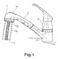
- the shower head 1 shown in FIGS. 1 and 2 is intended and suitable for a sink mixer 2, which can be a mixer tap, in particular a single-lever mixer tap, as shown, but which can also be a pure cold water or a pure hot water battery. Such a shower head can also be used for other fittings, in particular other mixer taps.
- the shower head 1 which can be seen in FIG. 1 has a handle 3 on which this shower head 1 can be handled.
- the handle 3 is followed by a hose, which cannot be seen here, which runs into the interior of the sink mixer 2, so that the shower head 1 can be handled relatively freely.
- the shower head 1 according to the invention is intended and suitable for a sink mixer 2 or the like, which is intended to be particularly suitable for connection to a low-pressure accumulator (open hot water accumulator).
- a low-pressure accumulator open hot water accumulator
- a shower head 1 according to the invention can also be used in conjunction with other water supply systems.
- the shower head initially has a water inlet 4 which receives water from a hose or other connection (not shown) via an inlet line 5 in the handle 3.
- the water inlet 4 opens into a receiving chamber 6 in the shower head 1, which is followed by a normal jet outlet 7 arranged approximately in the center of the shower head 1.
- This normal jet outlet 7 is followed by a usual turbulator 8.
- the normal jet outlet 7 concentrically surrounds a shower outlet 9 with a large number of small shower holes 10, which can also be seen in FIG. 1. 1 makes it clear that this shower head 1 can be switched over from operation with normal jet 11 to operation with shower jet 12.
- a changeover valve 13 is used for this changeover, which can again be clearly seen in FIG. 2.
- the changeover valve 13 In a normal position of the normal jet outlet 7, the changeover valve 13 connects to the water inlet 4 and separates the shower outlet 9 from the water inlet 4. This position is also shown in FIG. 2. In a shower position, however, the changeover valve 13 connects the shower spout 9 to the water inlet 4 and separates the normal jet outlet 7.
- a pushbutton 14 designed as a moisture-proof seal on the top of the shower head 1 is used to actuate the change-over valve 13 and, against the spring force of a spring element 15, is able to lower a valve body 16 in the axial direction when one presses this pushbutton 14.
- the valve body 16 is in the exemplary embodiment shown in FIG. 2, ie in the normal position, in sealing contact with an upper valve seat 17, so that there is a direct connection between the receiving chamber 6 and the normal jet outlet 7. If you press the push button 14, the valve body 16 is opposed the effect of the spring element 15 pressed down, thereby lifted from the valve seat 17 and brought sealingly to the valve seat 18.
- the valve body 16 is seated annularly on a piston rod 19, which can be axially displaced by the push button 14.
- this is only one possible exemplary embodiment for such a changeover valve 13.
- the changeover valve 13 is in the shower position, in which the receiving chamber 6 is connected directly to a shower chamber 20, which in turn is connected to the shower spout 9.
- bypass line 21 is integrated in detail in the changeover valve 13.
- the bypass line 21 can be arranged to a certain extent parallel to the changeover valve 13.
- the bypass line 21 is arranged in the valve body 16 of the changeover valve 13. This is shown in dashed lines here.
- This integrated design has the advantage that one the construction of the known shower head 1 as such can be left completely unchanged and only has to replace the valve body 16 in order to arrive at the shower head 1 according to the invention.
- the valve body 16 of the shower head 1 according to the invention in the exemplary embodiment shown here is, in a manner known per se, a seat valve body which can be displaced in the axial direction.
- the bypass line 21 is designed as a central, axial channel in the valve body 16.
- the design here is such that the valve body 16 is arranged on a piston rod 19 having the central axial channel and the piston rod 19 is open at the end at the end facing the normal spray outlet 7 and on the side facing the shower outlet 9 a side inlet opening 22 for has the channel forming the bypass line 21 or part of the bypass line.
- the teaching of the invention includes the measure to design the flow resistance of the bypass line 21 so that the maximum dynamic pressure occurring upstream of the bypass line 21 is less than the burst pressure of an associated low-pressure accumulator.
- a matching to different burst pressures is achieved in a particularly simple manner in that an insert which limits the effective flow resistance is interchangeably inserted in the bypass line.
- bypass line 21 is always open, so that the aforementioned slight leakage current can occur.
- a more complicated measure which, however, certainly precludes this leakage current when shower holes 10 are not clogged, is to arrange a pressure-dependent opening valve in the bypass line 21. This is not shown here.
Landscapes
- Nozzles (AREA)
- Bathtubs, Showers, And Their Attachments (AREA)
- Domestic Plumbing Installations (AREA)
- Compositions Of Oxide Ceramics (AREA)
- Sink And Installation For Waste Water (AREA)
- Safety Valves (AREA)
- Details Or Accessories Of Spraying Plant Or Apparatus (AREA)
- Massaging Devices (AREA)
- Devices For Medical Bathing And Washing (AREA)
- Bidet-Like Cleaning Device And Other Flush Toilet Accessories (AREA)
Description
- Die Erfindung betrifft einen Brausekopf für eine Spültischbatterie od. dgl., die für den Anschluß an einen Niederdruckspeicher (offener Heißwasserspeicher) geeignet ist, mit einem Wasserzulauf, einem, insbesondere mittig angeordneten Normalstrahlauslauf, einem, insbesondere den Normalstrahlauslauf konzentrisch umgebend angeordneten Brauseauslauf mit einer Vielzahl kleiner Brauselöcher und einem Umstellventil, wobei das Umstellventil in einer Normalstellung den Normalstrahlauslauf mit dem Wasserzulauf verbindet und den Brauseauslauf vom Wasserzulauf abtrennt und in einer Brausestellung den Brauseauslauf mit dem Wasserzulauf verbindet und den Normalstrahlauslauf vom Wasserzulauf abtrennt.
- Der bekannte Brausekopf, von dem die Erfindung ausgeht (IDEAL-STANDARD-Prospekt "CERAMIX COMBI" W 538 2 S), ist insbesondere für eine Spültischbatterie bestimmt und geeignet, eine entsprechende Konstruktion eines Brausekopfs kann aber auch an anderen Batterien, insbesondere Mischbatterien, Verwendung finden. Wesentlich für einen solchen Brausekopf ist dabei, daß er den Betrieb in zwei Strahlarten erlaubt, nämlich einerseits mit einem Normalstrahl, andererseits mit einem Brausestrahl. Der Normalstrahl tritt an einem Normalstrahlauslauf durch einen üblichen Turbulator od. dgl. aus. Der Brausestrahl hingegen tritt durch eine Vielzahl kleiner Brauselöcher eines Brauseauslaufs aus. In den meisten Fällen sind Brauselöcher des Brauseauslaufs konzentrisch um den Normalstrahlauslauf herum angeordnet.
- Ist ein zuvor erläuterter, bekannter Brausekopf an eine zentrale Kaltwasserversorgung und/oder Warmwasserversorgung angeschlossen, so ergeben sich keine größeren Anschlußprobleme. Das gleiche gilt bei Anschluß an einen Durchlauferhitzer. Bei Anschluß an einen Niederdruckspeicher, also einen offenen Heißwasserspeicher, muß man aber beachten, daß der Druck im Niederdruckspeicher keinesfalls so hoch steigen darf, daß ein Bersten des Niederdruckspeichers zu befürchten ist. Das hier angesprochene Berstproblem ist für Einhebelmischer allgemein erkannt worden und hat dazu geführt, daß man mit fest eingebauten Drosseln arbeitet, die den Wasserdurchfluß konstant halten, auch wenn sich der Wasserdruck ändert.
- Ungeachtet der Anwendung an sich bekannter Maßnahmen zur Verhinderung des Berstens eines Niederdruckspeichers hat es sich gezeigt, daß bei Einsatz des bekannten Brausekopfes nach wie vor eine Berstgefahr dann besteht, wenn bei maximaler Durchflußrate des Wassers von Normalstellung auf Brausestellung umgeschaltet wird. Dieses für diesen Brausekopf spezifische Berstproblem bedarf einer Lösung, so daß der Lehre der Erfindung die Aufgabe zugrundeliegt, einen für den Einsatz in Verbindung mit einem Niederdruckspeicher vollständig geeigneten Brausekopf anzugeben.
- Die zuvor aufgezeigte Aufgabe ist bei dem Brausekopf, von dem die Erfindung ausgeht, dadurch gelöst, daß im Umstellventil eine in Brausestellung wirksame Bypassleitung zwischen dem Wasserzulauf und dem Normalstrahlauslauf vorgesehen ist und daß der Strömungswiderstand der Bypassleitung größer ist als der Strömungswiderstand des Brauseauslaufs bei nicht zugesetzten Brauselöchern, aber der vor der Bypassleitung bei zugesetzten Brauselöchern betriebsmäßig maximal auftretende Staudruck kleiner ist als der Berstdruck eines zugeordneten Niederdruckspeichers. Es versteht sich von selbst, daß ein solcher Brausekopf durch die erfindungsgemäße Ausgestaltung in vollem Umfange für den Anschluß an einen Niederdruckspeicher geeignet ist, aber ebenso auch mit anders angeschlossenen Spültischbatterien od. dgl. eingesetzt werden kann. Ein erster Teil der Erfindung liegt in der Erkenntnis, daß das Bersten eines Niederdruckspeichers bei dem oben erläuterten Umschalten an einem Brausekopf der in Rede stehenden Art dann auftreten kann, wenn die Brauselöcher des Brauseauslaufs vollständig oder zum großen Teil durch Schmutz oder Kalkansatz zugesetzt sind. Beim Umschalten aus der Normalstellung mit geringem Strömungswiderstand in die Brausestellung ergibt sich in diesem Fall ein starker Druckschlag, da die Wasserströmung praktisch plötzlich blockiert wird. Ob eine solche Situation auftritt oder nicht, ist vom Hersteller nicht mehr zu beeinflussen, hängt vielmehr nur von der Sorgfalt ab, mit der der Benutzer die Brauselöcher des Brauseauslaufs offen hält. Als zweiter Teil der Erfindung ist nun, entgegen dem eigentlichen Wunsch, eine wirksame Umschaltung zwischen Normalstellung und Brausestellung zu realisieren, für die Brausestellung ein weiterer Strömungsweg geschaffen worden, der immer geöffnet ist und der sich auch mit Schmutz oder Kalkablagerungen normalerweise kaum zusetzen kann. Durch die Abstimmung des Strömungswiderstands dieser Bypassleitung bezogen auf den Strömungswiderstand des Brauseauslaufs bei nicht zugesetzten Brauselöchern wird erfindungsgemäß erreicht, daß normalerweise allenfalls eine geringfügige Leckströmung durch die Bypassleitung in den Normalstrahlauslauf strömt. Diese Leckströmung ist, selbst wenn sie auftreten sollte,in der Praxis nicht störend. Bei Umschaltung aus der Normalstellung in die Brausestellung im Falle zugesetzter Brauselöcher übernimmt aber die Bypassleitung strömungstechnisch die Funktion des Brauseauslaufs weitgehend oder gänzlich, wenn auch, wegen des höheren Strömungswiderstandes, auf einem höheren Druckniveau als bei nicht zugesetzten Brauselöchern. Der Strömungswiderstand der Bypassleitung ist dabei so bemessen, daß ein für den Niederdruckspeicher druckmäßig gefährlich werdender Druckschlag nicht auftreten kann.
- Es gibt nun verschiedene Möglichkeiten, die Lehre der Erfindung auszugestalten und weiterzubilden, wozu auf die dem Anspruch 1 nachgeordneten Ansprüche verwiesen werden darf. Im übrigen wird verwiesen auf die nachfolgende Erläuterung eines Ausführungsbeispiels anhand der Zeichnung. In der Zeichnung zeigt
- Fig. 1 in perspektivischer Ansicht eine Spültischbatterie mit daran angeord netem Brausekopf und
- Fig. 2 den Brausekopf aus Fig. 1 in einem Schnitt.
- Der in Fig. 1 und Fig. 2 dargestellte Brausekopf 1 ist bestimmt und geeignet für eine Spültischbatterie 2, die eine Mischbatterie, insbesondere eine Einhebel-Mischbatterie sein kann, wie dargestellt, die aber auch eine reine Kaltwasser oder eine reine Warmwasserbatterie sein kann. Auch für andere Armaturen, insbesondere andere Mischbatterien ist ein solcher Brausekopf einsetzbar. Der in Fig. 1 erkennbare Brausekopf 1 weist einen Handgriff 3 auf, an dem man diesen Brausekopf 1 handhaben kann. An den Handgriff 3 schließt sich ein in das Innere der Spültischbatterie 2 hinein verlaufender, hier nicht erkennbarer Schlauch an, so daß der Brausekopf 1 relativ frei gehandhabt werden kann.
- Wie im allgemeinen Teil der Beschreibung schon ausgeführt worden ist, ist der erfindungsgemäße Brausekopf 1 für eine Spültischbatterie 2 od. dgl. bestimmt und geeignet, die insbesondere für den Anschluß an einen Niederdruckspeicher (offener Heißwasserspeicher) geeignet sein soll. In Verbindung mit einem Niederdruckspeicher stellt sich das der Lehre zugrundeliegende Problem. Gleichwohl ist ein erfindungsgemäßer Brausekopf 1 auch in Verbindung mit anderen Wasserzulaufsystemen einsetzbar.
- Der Brausekopf 1 weist, wie Fig. 2 erkennen läßt, zunächst einen Wasserzulauf 4 auf, der über eine Zulaufleitung 5 im Handgriff 3 Wasser aus einem nicht dargestellten Schlauch oder einem anderen Anschluß erhält. Der Wasserzulauf 4 mündet in einer Aufnahmekammer 6 im Brausekopf 1, an die sich ein etwa mittig im Brausekopf 1 angeordneter Normalstrahlauslauf 7 anschließt. Diesem Normalstrahlauslauf 7 ist hier ein üblicher Turbulator 8 nachgeordnet. Im hier dargestellten Ausführungsbeispiel umgibt den Normalstrahlauslauf 7 konzentrisch ein Brauseauslauf 9 mit einer Vielzahl kleiner Brauselöcher 10, die auch in Fig. 1 erkennbar sind. Fig. 1 macht dabei deutlich, daß dieser Brausekopf 1 vom Betrieb mit Normalstrahl 11 in den betrieb mit Brausestrahl 12 umschaltbar ist. Zu dieser Umschaltung dient ein Umstellventil 13, das nun wiederum in Fig. 2 gut zu erkennen ist. Das Umstellventil 13 verbindet in einer Normalstellung des Normalstrahlauslaufs 7 mit dem Wasserzulauf 4 und trennt den Brauseauslauf 9 vom Wasserzulauf 4 ab. Diese Stellung zeigt gerade auch Fig. 2. In einer Brausestellung hingegen verbindet das Umstellventil 13 den Brauseauslauf 9 mit dem Wasserzulauf 4 und trennt den Normalstrahlauslauf 7 ab.
- Zur Betätigung des Umstellventils 13 dient eine als Feuchtraumdichtung ausgeführte Drucktaste 14 an der Oberseite des Brausekopfes 1, die entgegen der Federkraft eines Federelements 15 einen Ventilkörper 16 in axialer Richtung abzusenken vermag, wenn man auf diese Drucktaste 14 drückt. Der Ventilkörper 16 befindet sich im in Fig. 2 dargestellten Ausführungsbeispiel, also in Normalstellung, in abdichtender Anlage an einem oberen Ventilsitz 17, so daß sich eine direkte Verbindung der Aufnahmekammer 6 mit dem Normalstrahlauslauf 7 ergibt. Drückt man auf die Drucktaste 14, so wird der Ventilkörper 16 entgegen der Wirkung des Federelements 15 nach unten gedrückt, dabei vom Ventilsitz 17 abgehoben und abdichtend am Ventilsitz 18 zur Anlage gebracht. Der Ventilkörper 16 sitzt hier im übrigen ringförmig auf einer Kolbenstange 19, die von der Drucktaste 14 her axial verschoben werden kann. Das ist aber nur ein mögliches Ausführungsbeispiel für ein solches Umstellventil 13.
- In der zuvor an zweiter Stelle erläuterten Funktionsstellung, die in Fig. 2 nicht dargestellt ist, befindet sich das Umstellventil 13 in Brausestellung, in der die Aufnahmekammer 6 direkt mit einer Brausekammer 20 verbunden ist, die ihrerseits mit dem Brauseauslauf 9 verbunden ist.
- Im Grundsatz ist es natürlich anzustreben und bei dem Brausekopf 1, von dem die Erfindung ausgeht, auch realisiert, daß alles durch den Wasserzulauf 4 zulaufende Wasser in Normalstellung durch den Normalstrahlauslauf 7 strömt und in Brausestellung durch die Brauselöcher 10 des Brauseauslaufs 9. Das Umstellventil 13 muß also insoweit als echtes Umschaltventil wirken. Von diesem grundlegenden, im Stand der Technik verwirklichten Konzept wendet sich die Erfindung ein klein wenig ab, um den erwünschten Berstschutz eines Niederdruckspeichers zu erreichen. Erfindungsgemäß gilt nämlich nun, daß im Umstellventil 13 eine in Brausestellung wirksame Bypassleitung 21 zwischen dem Wasserzulauf 4 und dem Normalstrahlauslauf 7 vorgesehen ist und daß der Strömungswiderstand der Bypassleitung 21 größer ist als der Strömungswiderstand des Brauseauslaufs 9 bei nicht zugesetzten Brauselöchern 10, aber der vor der Bypassleitung 21 bei zugesetzten Brauselöchern 10 betriebsmäßig maximal auftretende Staudruck kleiner ist als der Berstdruck eines zugeordneten Niederdruckspeichers. Damit werden die weiter oben erläuterten Vorteile erreicht.
- Wie die Bypassleitung 21 im einzelnen im Umstellventil 13 integriert wird, ist einer Vielzahl von Variationen offen. Beispielsweise kann die Bypassleitung 21 zum Umstellventil 13 gewissermaßen parallel angeordnet sein. Im dargestellten und insoweit bevorzugten Ausführungsbeispielgilt nun aber, daß die Bypassleitung 21 im Ventilkörper 16 des Umstellventils 13 angeordnet ist. Das ist hier gestrichelt dargestellt. Diese integrierte Gestaltung hat den Vorteil, daß man die Konstruktion des bekannten Brausekopfes 1 als solche völlig unverändert lassen kann und nur den Ventilkörper 16 auswechseln muß, um zu dem erfindungsgemäßen Brausekopf 1 zu gelangen.
- Wie zuvor schon erläutert worden ist, handelt es sich beim Ventilkörper 16 des erfindungsgemäßen Brausekopfes 1 im hier dargestellten Ausführungsbeispiel in an sich bekannter Weise um einen in axialer Richtung verschiebbaren Sitzventilkörper. Hierbei gilt nun, daß die Bypassleitung 21 als mittiger, axialer Kanal in dem Ventilkörper 16 ausgeführt ist. Konkret ist die Gestaltung hier so getroffen, daß der Ventilkörper 16 auf einer den mittigen axialen Kanal aufweisenden Kolbenstange 19 angeordnet ist und die Kolbenstange 19 an dem dem Normalstrahlauslauf 7 zugewandten Ende stirnseitig offen ist und auf der dem Brauseauslauf 9 zugewandten Seite eine seitliche Eintrittsöffnung 22 für den die Bypassleitung 21 bzw. einen Teil der Bypassleitung bildenden Kanal aufweist.
- Die Lehre der Erfindung beinhaltet die Maßnahme, den Strömungswiderstand der Bypassleitung 21 so zu gestalten, daß der vor der Bypassleitung 21 betriebsmäßig maximal auftretende Staudruck kleiner ist als der Berstdruck eines zugeordneten Niederdruckspeichers. Eine Abstimmung auf unterschiedliche Berstdrücke gelingt auf ganz besonders einfacher Weise dadurch, daß in der Bypassleitung ein den wirksamen Strömungswiderstand begrenzender Einsatz auswechselbar eingesetzt ist.
- Im hier dargestellten und bevorzugten Ausführungsbeispiel ist die Bypassleitung 21 stets geöffnet, so daß sich der zuvor erwähnte geringfügige Leckstrom einstellen kann. Eine kompliziertere, aber diesen Leckstrom bei nicht zugesetzten Brauselöchern 10 mit Sicherheit ausschließende Maßnahme besteht darin, in der Bypassleitung 21 ein druckabhängig öffnendes Ventil anzuordnen. Das ist hier nicht dargestellt.
Claims (6)
Priority Applications (1)
| Application Number | Priority Date | Filing Date | Title |
|---|---|---|---|
| AT90902218T ATE76786T1 (de) | 1989-01-28 | 1990-01-24 | Brausekopf fuer eine spueltischbatterie od. dgl. |
Applications Claiming Priority (2)
| Application Number | Priority Date | Filing Date | Title |
|---|---|---|---|
| DE3902588 | 1989-01-28 | ||
| DE3902588A DE3902588C1 (de) | 1989-01-28 | 1989-01-28 |
Publications (2)
| Publication Number | Publication Date |
|---|---|
| EP0407547A1 EP0407547A1 (de) | 1991-01-16 |
| EP0407547B1 true EP0407547B1 (de) | 1992-06-03 |
Family
ID=6373008
Family Applications (1)
| Application Number | Title | Priority Date | Filing Date |
|---|---|---|---|
| EP90902218A Expired - Lifetime EP0407547B1 (de) | 1989-01-28 | 1990-01-24 | Brausekopf für eine spültischbatterie od. dgl. |
Country Status (11)
| Country | Link |
|---|---|
| US (1) | US5145114A (de) |
| EP (1) | EP0407547B1 (de) |
| JP (1) | JPH0815576B2 (de) |
| KR (1) | KR950004144B1 (de) |
| AT (1) | ATE76786T1 (de) |
| AU (1) | AU4964190A (de) |
| BR (1) | BR9004924A (de) |
| DE (2) | DE3902588C1 (de) |
| DK (1) | DK0407547T3 (de) |
| ES (1) | ES2033167T3 (de) |
| WO (1) | WO1990008598A1 (de) |
Families Citing this family (119)
| Publication number | Priority date | Publication date | Assignee | Title |
|---|---|---|---|---|
| GB2259029B (en) * | 1991-08-29 | 1995-04-26 | Hozelock Ltd | Water spray gun |
| DE9314443U1 (de) * | 1993-09-24 | 1993-12-02 | H. Weidmann Ag, Rapperswil, St. Gallen | Wasserauslauf für eine Sanitärarmatur |
| IT232026Y1 (it) * | 1993-12-20 | 1999-08-10 | Amfag Srl | Corpo di doccia |
| DE19509659C1 (de) * | 1995-03-17 | 1996-11-21 | Hansa Metallwerke Ag | Mehrfunktions-Handbrause |
| DE19509661C2 (de) * | 1995-03-17 | 1999-02-04 | Hansa Metallwerke Ag | Mehrfunktions-Handbrause |
| DE19527232A1 (de) * | 1995-07-26 | 1997-01-30 | Grohe Armaturen Friedrich | Auslaufarmatur |
| US5722595A (en) * | 1995-10-30 | 1998-03-03 | Component Hardware Group, Inc. | Grip assembly |
| US5735467A (en) * | 1996-09-05 | 1998-04-07 | Lee; Cheng-Chung | Three-way adjustable shower device |
| US5971299A (en) * | 1997-01-21 | 1999-10-26 | Moen Incorporated | Kitchen faucet side spray |
| US5806771A (en) * | 1997-01-21 | 1998-09-15 | Moen Incorporated | Kitchen faucet side spray |
| IT242829Y1 (it) * | 1997-07-15 | 2002-02-04 | Amfag Spa | Corpo di doccia |
| USD392027S (en) | 1997-08-08 | 1998-03-10 | Emhart Inc. | Spout |
| USD403751S (en) * | 1997-10-23 | 1999-01-05 | Emhart Inc. | Spout |
| USD399931S (en) | 1997-12-02 | 1998-10-20 | Emhart Inc. | Spout |
| DE19803554A1 (de) * | 1998-01-30 | 1999-08-05 | Grohe Armaturen Friedrich | Wasserausflußarmatur |
| DE19815956A1 (de) * | 1998-04-09 | 1999-10-14 | Scheffer Ohg Franz | Handbrause mit wasserführendem Steckinnenrohr |
| US6186414B1 (en) * | 1998-09-09 | 2001-02-13 | Moen Incorporated | Fluid delivery from a spray head having a moving nozzle |
| IT248221Y1 (it) * | 1999-03-22 | 2002-12-16 | Amfag Spa | Disco di uscita del getto d'acqua in doccia da cucina |
| US6151729A (en) * | 1999-10-28 | 2000-11-28 | Chya Ye Industrial Co., Ltd. | Switch valve for use in a rinsing shower head mounted to a kitchen sink |
| US6290147B1 (en) | 2000-09-19 | 2001-09-18 | Moen Incorporated | Pullout faucet wand button mechanism |
| WO2002047765A1 (en) | 2000-12-12 | 2002-06-20 | Water Pik, Inc. | Shower head assembly |
| CA2343678C (en) * | 2001-04-11 | 2005-05-31 | Globe Union Industrial Corp. | Water spraying gun |
| ITMN20010026A1 (it) * | 2001-06-04 | 2002-12-04 | Fabrizio Nobili | Testata di erogazione dell'acqua in doccia |
| US20020185553A1 (en) * | 2001-06-08 | 2002-12-12 | Benstead Evan A. | Spray head |
| USD485887S1 (en) | 2002-12-10 | 2004-01-27 | Water Pik, Inc. | Pan head style shower head |
| US7114666B2 (en) | 2002-12-10 | 2006-10-03 | Water Pik, Inc. | Dual massage shower head |
| US6938837B2 (en) * | 2003-01-23 | 2005-09-06 | Masco Corporation Of Indiana | Faucet spray head assembly |
| US7070125B2 (en) * | 2003-05-16 | 2006-07-04 | Newfrey Llc | Multi-pattern pull-out spray head |
| US7533906B2 (en) | 2003-10-14 | 2009-05-19 | Water Pik, Inc. | Rotatable and pivotable connector |
| ITMN20030043A1 (it) * | 2003-11-14 | 2005-05-15 | Amfag Spa | Doccetta per lavello |
| ITMN20030042A1 (it) * | 2003-11-14 | 2005-05-15 | Amfag Spa | Doccetta apri-chiudi |
| EP1557501A1 (de) * | 2004-01-26 | 2005-07-27 | Fabrizio Nobili | Einrichtung zur Abgabe von aufbereitetem Wasser, Hahn und Versorgungsrohr dafür |
| GB2428990B (en) * | 2004-05-07 | 2007-08-29 | Newfrey Llc | Docking collar for a pull-out spray head |
| ATE535309T1 (de) * | 2004-07-16 | 2011-12-15 | Weidmann Plastics Tech Ag | Brause |
| ITMI20041472A1 (it) * | 2004-07-21 | 2004-10-21 | Fabrizio Nobili | Doccetta per docce in genere ed in particolare per docce manuali per lavelli e simili |
| USD527440S1 (en) | 2004-09-01 | 2006-08-29 | Water Pik, Inc. | Drenching shower head |
| US7740186B2 (en) | 2004-09-01 | 2010-06-22 | Water Pik, Inc. | Drenching shower head |
| USD533253S1 (en) | 2004-11-03 | 2006-12-05 | Water Pik, Inc. | Elliptical shower head |
| US7343930B2 (en) | 2004-12-03 | 2008-03-18 | Masco Corporation Of Indiana | Sprayer with non-faucet control |
| DE502006002331D1 (de) * | 2005-03-11 | 2009-01-22 | Weidmann Plastics Tech Ag | Brausekopf |
| US20060219822A1 (en) * | 2005-03-17 | 2006-10-05 | Alsons Corporation | Dual volume shower head system |
| USD555763S1 (en) | 2005-04-25 | 2007-11-20 | Fabrizio Nobili | Shower head |
| USD555768S1 (en) | 2005-04-25 | 2007-11-20 | Fabrizio Nobili | Shower head |
| US11267003B2 (en) | 2005-05-13 | 2022-03-08 | Delta Faucet Company | Power sprayer |
| CN101180132B (zh) | 2005-05-13 | 2010-11-24 | 印第安纳马斯科公司 | 动力喷水器 |
| US7909061B2 (en) | 2005-06-17 | 2011-03-22 | Masco Corporation Of Indiana | Magnetic coupling for sprayheads |
| US7753079B2 (en) | 2005-06-17 | 2010-07-13 | Masco Corporation Of Indiana | Magnetic coupling for sprayheads |
| US20060289680A1 (en) * | 2005-06-22 | 2006-12-28 | Chung-I Huang | Shower |
| EP1736695B1 (de) | 2005-06-24 | 2008-07-09 | Weidmann Plastics Technology AG | Ventil, insbesondere für eine Sanitärarmatur |
| ITMI20051252A1 (it) * | 2005-07-01 | 2007-01-02 | Fabrizio Nobili | Gruppo per l'erogazione differenziabile di acqua trattata e di acqua di rete |
| ITMI20051405A1 (it) * | 2005-07-21 | 2007-01-22 | Fabrizio Nobili | Doccetta per l'erogazione differeenziata di acqua trattata e di acqua di rete |
| USD572801S1 (en) | 2005-12-14 | 2008-07-08 | Moen Incorporated | Spout |
| US7871020B2 (en) | 2006-01-26 | 2011-01-18 | Masco Corporation Of Indiana | Faucet spray head with volume control |
| US8424781B2 (en) | 2006-02-06 | 2013-04-23 | Masco Corporation Of Indiana | Power sprayer |
| ITMI20060357A1 (it) * | 2006-02-28 | 2007-09-01 | Fabrizio Nobili | Doccetta per lavello con variazione del getto di erogazione e regolazione della portata |
| ITMI20060358A1 (it) * | 2006-02-28 | 2007-09-01 | Fabrizio Nobili | Doccetta per lavello con variazione del getto di erogazione e regolazione della portata |
| ITMI20060511A1 (it) * | 2006-03-21 | 2007-09-22 | Fabrizio Nobili | Doccetta ad azionamento semplificato particolarmente per lavelli da cucina |
| WO2007124455A2 (en) | 2006-04-20 | 2007-11-01 | Water Pik, Inc. | Converging spray showerhead |
| US20080006707A1 (en) * | 2006-07-06 | 2008-01-10 | Fabrizio Nobili | Showerhead with simplified actuator |
| EP1884693A1 (de) * | 2006-08-03 | 2008-02-06 | Fabrizio Nobili | Wasserhahn |
| US7909269B2 (en) * | 2006-09-19 | 2011-03-22 | Kohler Co. | Faucet spray control assembly |
| US8152078B2 (en) | 2006-10-25 | 2012-04-10 | Masco Corporation Of Indiana | Faucet spray head |
| US7789326B2 (en) | 2006-12-29 | 2010-09-07 | Water Pik, Inc. | Handheld showerhead with mode control and method of selecting a handheld showerhead mode |
| US8020787B2 (en) | 2006-11-29 | 2011-09-20 | Water Pik, Inc. | Showerhead system |
| USD577793S1 (en) | 2006-11-29 | 2008-09-30 | Water Pik, Inc. | Showerhead assembly |
| USD577099S1 (en) | 2006-11-29 | 2008-09-16 | Water Pik, Inc. | Showerhead assembly |
| US8366024B2 (en) | 2006-12-28 | 2013-02-05 | Water Pik, Inc. | Low speed pulsating showerhead |
| US7770822B2 (en) | 2006-12-28 | 2010-08-10 | Water Pik, Inc. | Hand shower with an extendable handle |
| US8794543B2 (en) | 2006-12-28 | 2014-08-05 | Water Pik, Inc. | Low-speed pulsating showerhead |
| US8371618B2 (en) | 2007-05-04 | 2013-02-12 | Water Pik, Inc. | Hidden pivot attachment for showers and method of making same |
| US20090032610A1 (en) * | 2007-07-30 | 2009-02-05 | Michael Scot Rosko | Anti-Drip fluid delivery device |
| USD590048S1 (en) | 2007-12-20 | 2009-04-07 | Water Pik, Inc. | Hand shower |
| USD603935S1 (en) | 2007-12-20 | 2009-11-10 | Water Pik, Inc. | Hand shower |
| USD580012S1 (en) | 2007-12-20 | 2008-11-04 | Water Pik, Inc. | Showerhead |
| USD592278S1 (en) | 2007-12-20 | 2009-05-12 | Water Pik, Inc. | Showerhead |
| USD580513S1 (en) | 2007-12-20 | 2008-11-11 | Water Pik, Inc. | Hand shower |
| USD581014S1 (en) | 2007-12-20 | 2008-11-18 | Water Pik, Inc. | Hand shower |
| USD605731S1 (en) | 2007-12-26 | 2009-12-08 | Water Pik, Inc. | Bracket for hand shower |
| US7766260B2 (en) * | 2008-02-12 | 2010-08-03 | Wen-Yi Lin | Showerhead |
| US9272295B2 (en) * | 2008-02-12 | 2016-03-01 | Kohler Co. | Sprayer assembly |
| FR2930167B1 (fr) * | 2008-04-17 | 2010-05-07 | Inst Francais Du Petrole | Dispositif portable d'extinction d'incendie |
| USD624156S1 (en) | 2008-04-30 | 2010-09-21 | Water Pik, Inc. | Pivot ball attachment |
| EP2156897A1 (de) * | 2008-08-18 | 2010-02-24 | Shower Pro S.r.L. | Multifunktionsbrausekopf |
| CA2678769C (en) | 2008-09-15 | 2014-07-29 | Water Pik, Inc. | Shower assembly with radial mode changer |
| USD600777S1 (en) | 2008-09-29 | 2009-09-22 | Water Pik, Inc. | Showerhead assembly |
| USD616061S1 (en) | 2008-09-29 | 2010-05-18 | Water Pik, Inc. | Showerhead assembly |
| USD606623S1 (en) | 2008-09-29 | 2009-12-22 | Water Pik, Inc. | Hand shower |
| USD625776S1 (en) | 2009-10-05 | 2010-10-19 | Water Pik, Inc. | Showerhead |
| US8448667B2 (en) | 2009-10-19 | 2013-05-28 | Masco Corporation Of Indiana | Multi-function pull-out wand |
| US8616470B2 (en) | 2010-08-25 | 2013-12-31 | Water Pik, Inc. | Mode control valve in showerhead connector |
| USD678467S1 (en) | 2012-01-27 | 2013-03-19 | Water Pik, Inc. | Ring-shaped handheld showerhead |
| USD678463S1 (en) | 2012-01-27 | 2013-03-19 | Water Pik, Inc. | Ring-shaped wall mount showerhead |
| CA2976867C (en) | 2012-06-22 | 2021-03-02 | Water Pik, Inc. | Bracket for showerhead with integral flow control |
| US9259743B2 (en) | 2013-03-14 | 2016-02-16 | Kohler Co. | Splashless spray head |
| US9545639B2 (en) | 2013-03-15 | 2017-01-17 | Delta Faucet Company | Multi-function wand assembly |
| CN111790529B (zh) | 2013-06-13 | 2024-06-11 | 洁碧有限公司 | 具有引擎释放的花洒 |
| USD744614S1 (en) | 2014-06-13 | 2015-12-01 | Water Pik, Inc. | Wall mount showerhead |
| USD744065S1 (en) | 2014-06-13 | 2015-11-24 | Water Pik, Inc. | Handheld showerhead |
| USD744066S1 (en) | 2014-06-13 | 2015-11-24 | Water Pik, Inc. | Wall mount showerhead |
| USD744612S1 (en) | 2014-06-13 | 2015-12-01 | Water Pik, Inc. | Handheld showerhead |
| USD744064S1 (en) | 2014-06-13 | 2015-11-24 | Water Pik, Inc. | Handheld showerhead |
| USD745111S1 (en) | 2014-06-13 | 2015-12-08 | Water Pik, Inc. | Wall mount showerhead |
| USD744611S1 (en) | 2014-06-13 | 2015-12-01 | Water Pik, Inc. | Handheld showerhead |
| JP6656842B2 (ja) * | 2015-08-13 | 2020-03-04 | 株式会社Kvk | 水栓の吐水切換機構 |
| US9550195B1 (en) * | 2015-09-16 | 2017-01-24 | Xiamen Solex High-Tech Industries Co., Ltd. | Shower head |
| US9707572B2 (en) * | 2015-12-18 | 2017-07-18 | Kohler Co. | Multi-function splashless sprayhead |
| EP3411155B1 (de) | 2016-02-01 | 2020-03-25 | Water Pik, Inc. | Tragbarer sprühstab für haustiere |
| USD803981S1 (en) | 2016-02-01 | 2017-11-28 | Water Pik, Inc. | Handheld spray nozzle |
| USD970684S1 (en) | 2016-04-15 | 2022-11-22 | Water Pik, Inc. | Showerhead |
| US10265710B2 (en) | 2016-04-15 | 2019-04-23 | Water Pik, Inc. | Showerhead with dual oscillating massage |
| CN106000689B (zh) * | 2016-07-28 | 2018-12-25 | 厦门建霖健康家居股份有限公司 | 双按钮花洒及其工作方法 |
| EP3509754B1 (de) | 2016-09-08 | 2021-06-30 | Water Pik, Inc. | Pausenanordnung für duschköpfe |
| USD843549S1 (en) | 2017-07-19 | 2019-03-19 | Water Pik, Inc. | Handheld spray nozzle |
| USD872227S1 (en) | 2018-04-20 | 2020-01-07 | Water Pik, Inc. | Handheld spray device |
| USD944925S1 (en) * | 2020-08-13 | 2022-03-01 | Delta Faucet Company | Faucet sprayhead |
| CN213176885U (zh) * | 2020-09-10 | 2021-05-11 | 厦门洁淋卫浴科技有限公司 | 一种密封切换机构 |
| USD940275S1 (en) * | 2020-09-22 | 2022-01-04 | Xinrui Zhang | Shower head |
| USD940274S1 (en) * | 2020-09-22 | 2022-01-04 | Xinrui Zhang | Shower head |
| USD957571S1 (en) * | 2020-10-16 | 2022-07-12 | Kohler Co. | Handshower |
Family Cites Families (9)
| Publication number | Priority date | Publication date | Assignee | Title |
|---|---|---|---|---|
| US165111A (en) * | 1875-06-29 | Improvement in waterxsprinklin | ||
| US2329087A (en) * | 1941-08-30 | 1943-09-07 | Eaton Mfg Co | Valve construction |
| CA1092793A (en) * | 1978-07-03 | 1981-01-06 | Wendel G. Brown | Method for manufacturing silicone carbide bodies |
| US4221337A (en) * | 1979-01-17 | 1980-09-09 | Shames Sidney J | Aerator and spray combination |
| CH646499A5 (de) * | 1980-05-08 | 1984-11-30 | Karrer Weber & Cie Ag | Sanitaer-wasserauslaufarmatur zum umstellen von strahl auf brause. |
| DE3047336C2 (de) * | 1980-12-16 | 1986-05-28 | Friedrich Grohe Armaturenfabrik Gmbh & Co, 5870 Hemer | Brauseeinrichtung |
| DE8204732U1 (de) * | 1982-02-20 | 1982-05-19 | Hans Grohe Gmbh & Co Kg, 7622 Schiltach | Brausekopf |
| DE3413552A1 (de) * | 1984-04-11 | 1985-10-24 | Hansa Metallwerke Ag, 7000 Stuttgart | Brause |
| JPH0689945B2 (ja) * | 1987-03-19 | 1994-11-14 | 松下電器産業株式会社 | 給湯器 |
-
1989
- 1989-01-28 DE DE3902588A patent/DE3902588C1/de not_active Expired - Fee Related
-
1990
- 1990-01-24 ES ES199090902218T patent/ES2033167T3/es not_active Expired - Lifetime
- 1990-01-24 BR BR909004924A patent/BR9004924A/pt not_active IP Right Cessation
- 1990-01-24 KR KR1019900702189A patent/KR950004144B1/ko not_active Expired - Fee Related
- 1990-01-24 AT AT90902218T patent/ATE76786T1/de active
- 1990-01-24 WO PCT/EP1990/000132 patent/WO1990008598A1/de not_active Ceased
- 1990-01-24 DE DE9090902218T patent/DE59000145D1/de not_active Expired - Fee Related
- 1990-01-24 DK DK90902218.8T patent/DK0407547T3/da active
- 1990-01-24 JP JP2502587A patent/JPH0815576B2/ja not_active Expired - Fee Related
- 1990-01-24 EP EP90902218A patent/EP0407547B1/de not_active Expired - Lifetime
- 1990-01-24 US US07/585,116 patent/US5145114A/en not_active Expired - Lifetime
- 1990-01-24 AU AU49641/90A patent/AU4964190A/en not_active Abandoned
Also Published As
| Publication number | Publication date |
|---|---|
| KR950004144B1 (ko) | 1995-04-27 |
| DE59000145D1 (de) | 1992-07-09 |
| WO1990008598A1 (de) | 1990-08-09 |
| AU4964190A (en) | 1990-08-24 |
| KR910700101A (ko) | 1991-03-13 |
| ATE76786T1 (de) | 1992-06-15 |
| DK0407547T3 (da) | 1992-07-20 |
| BR9004924A (pt) | 1991-08-06 |
| JPH0815576B2 (ja) | 1996-02-21 |
| JPH03504823A (ja) | 1991-10-24 |
| ES2033167T3 (es) | 1993-03-01 |
| EP0407547A1 (de) | 1991-01-16 |
| DE3902588C1 (de) | 1990-03-15 |
| US5145114A (en) | 1992-09-08 |
Similar Documents
| Publication | Publication Date | Title |
|---|---|---|
| EP0407547B1 (de) | Brausekopf für eine spültischbatterie od. dgl. | |
| DE69408058T2 (de) | Umstellventilkartusche | |
| EP3172634B1 (de) | Regelarmatur | |
| DE69613590T2 (de) | Umschaltventil | |
| DE4328200A1 (de) | Kontrollventileinrichtung, insbesondere für Duschen | |
| DE3109617A1 (de) | Ventil fuer eine sanitaere wassermischarmatur | |
| DE1932994A1 (de) | Stromregelventil | |
| DE102013107762A1 (de) | Durchflussregelventil | |
| DE3333518A1 (de) | Dreiwege-kugelhahn | |
| DE1600733A1 (de) | Druckminderer | |
| DE3039677A1 (de) | Druckknopf-wasserhahn | |
| DE10305394B4 (de) | Flüssigkeitsventil für Heiz- und/oder Kühlanlagen | |
| DE2716831C2 (de) | Mischventil | |
| DE102005006790A1 (de) | Ventilanordnung mit druckabhängig gesteuertem Ventil | |
| DE202608C (de) | ||
| DE2020075A1 (de) | Mischventil,insbesondere fuer Wasser und Wasserdampf | |
| DE19813296A1 (de) | Mischbatterie | |
| EP0927580A1 (de) | Handbrause | |
| DE19850810B4 (de) | Anschlussarmatur mit einem Heizölfilter für Heizungsanlagen | |
| DE4409498B4 (de) | Wassermischventil | |
| DE2012827C3 (de) | Ventilaufsatz | |
| DE2110559A1 (de) | Thermostatisch gesteuerte Mischarmatur fuer einen Durchlauferhitzer | |
| EP2644789B1 (de) | Modularer Bausatz für Rohrtrenneranordnungen | |
| DE2408208A1 (de) | Mischbatterie fuer kalt- und warmwasser mit zwei drucktastenventilen | |
| DE4141172B4 (de) | Vorrichtung zum Umstellen eines Ventilgliedes an einer Sanitärarmatur |
Legal Events
| Date | Code | Title | Description |
|---|---|---|---|
| PUAI | Public reference made under article 153(3) epc to a published international application that has entered the european phase |
Free format text: ORIGINAL CODE: 0009012 |
|
| 17P | Request for examination filed |
Effective date: 19900908 |
|
| AK | Designated contracting states |
Kind code of ref document: A1 Designated state(s): AT BE CH DE DK ES FR GB IT LI LU NL SE |
|
| 17Q | First examination report despatched |
Effective date: 19911111 |
|
| GRAA | (expected) grant |
Free format text: ORIGINAL CODE: 0009210 |
|
| AK | Designated contracting states |
Kind code of ref document: B1 Designated state(s): AT BE CH DE DK ES FR GB IT LI LU NL SE |
|
| REF | Corresponds to: |
Ref document number: 76786 Country of ref document: AT Date of ref document: 19920615 Kind code of ref document: T |
|
| ITF | It: translation for a ep patent filed | ||
| REF | Corresponds to: |
Ref document number: 59000145 Country of ref document: DE Date of ref document: 19920709 |
|
| GBT | Gb: translation of ep patent filed (gb section 77(6)(a)/1977) | ||
| REG | Reference to a national code |
Ref country code: DK Ref legal event code: T3 |
|
| ET | Fr: translation filed | ||
| PGFP | Annual fee paid to national office [announced via postgrant information from national office to epo] |
Ref country code: LU Payment date: 19930121 Year of fee payment: 4 |
|
| REG | Reference to a national code |
Ref country code: ES Ref legal event code: FG2A Ref document number: 2033167 Country of ref document: ES Kind code of ref document: T3 |
|
| PLBE | No opposition filed within time limit |
Free format text: ORIGINAL CODE: 0009261 |
|
| STAA | Information on the status of an ep patent application or granted ep patent |
Free format text: STATUS: NO OPPOSITION FILED WITHIN TIME LIMIT |
|
| EPTA | Lu: last paid annual fee | ||
| 26N | No opposition filed | ||
| PG25 | Lapsed in a contracting state [announced via postgrant information from national office to epo] |
Ref country code: LU Free format text: LAPSE BECAUSE OF NON-PAYMENT OF DUE FEES Effective date: 19940124 |
|
| PGFP | Annual fee paid to national office [announced via postgrant information from national office to epo] |
Ref country code: FR Payment date: 19941228 Year of fee payment: 6 |
|
| PGFP | Annual fee paid to national office [announced via postgrant information from national office to epo] |
Ref country code: GB Payment date: 19941229 Year of fee payment: 6 |
|
| PGFP | Annual fee paid to national office [announced via postgrant information from national office to epo] |
Ref country code: BE Payment date: 19941230 Year of fee payment: 6 |
|
| PGFP | Annual fee paid to national office [announced via postgrant information from national office to epo] |
Ref country code: ES Payment date: 19950105 Year of fee payment: 6 |
|
| PGFP | Annual fee paid to national office [announced via postgrant information from national office to epo] |
Ref country code: DK Payment date: 19950117 Year of fee payment: 6 |
|
| PGFP | Annual fee paid to national office [announced via postgrant information from national office to epo] |
Ref country code: AT Payment date: 19950118 Year of fee payment: 6 |
|
| PGFP | Annual fee paid to national office [announced via postgrant information from national office to epo] |
Ref country code: CH Payment date: 19950126 Year of fee payment: 6 |
|
| EAL | Se: european patent in force in sweden |
Ref document number: 90902218.8 |
|
| PGFP | Annual fee paid to national office [announced via postgrant information from national office to epo] |
Ref country code: SE Payment date: 19950131 Year of fee payment: 6 Ref country code: NL Payment date: 19950131 Year of fee payment: 6 |
|
| PG25 | Lapsed in a contracting state [announced via postgrant information from national office to epo] |
Ref country code: GB Effective date: 19960124 Ref country code: DK Effective date: 19960124 Ref country code: AT Effective date: 19960124 |
|
| REG | Reference to a national code |
Ref country code: DK Ref legal event code: EBP |
|
| PG25 | Lapsed in a contracting state [announced via postgrant information from national office to epo] |
Ref country code: SE Effective date: 19960125 Ref country code: ES Free format text: LAPSE BECAUSE OF NON-PAYMENT OF DUE FEES Effective date: 19960125 |
|
| PG25 | Lapsed in a contracting state [announced via postgrant information from national office to epo] |
Ref country code: LI Effective date: 19960131 Ref country code: CH Effective date: 19960131 Ref country code: BE Effective date: 19960131 |
|
| BERE | Be: lapsed |
Owner name: IDEAL-STANDARD G.M.B.H. Effective date: 19960131 |
|
| PG25 | Lapsed in a contracting state [announced via postgrant information from national office to epo] |
Ref country code: NL Effective date: 19960801 |
|
| GBPC | Gb: european patent ceased through non-payment of renewal fee |
Effective date: 19960124 |
|
| REG | Reference to a national code |
Ref country code: CH Ref legal event code: PL |
|
| PG25 | Lapsed in a contracting state [announced via postgrant information from national office to epo] |
Ref country code: FR Effective date: 19960930 |
|
| NLV4 | Nl: lapsed or anulled due to non-payment of the annual fee |
Effective date: 19960801 |
|
| EUG | Se: european patent has lapsed |
Ref document number: 90902218.8 |
|
| REG | Reference to a national code |
Ref country code: FR Ref legal event code: ST |
|
| REG | Reference to a national code |
Ref country code: ES Ref legal event code: FD2A Effective date: 19990503 |
|
| PGFP | Annual fee paid to national office [announced via postgrant information from national office to epo] |
Ref country code: DE Payment date: 20041228 Year of fee payment: 16 |
|
| PGFP | Annual fee paid to national office [announced via postgrant information from national office to epo] |
Ref country code: IT Payment date: 20060131 Year of fee payment: 17 |
|
| PG25 | Lapsed in a contracting state [announced via postgrant information from national office to epo] |
Ref country code: DE Free format text: LAPSE BECAUSE OF NON-PAYMENT OF DUE FEES Effective date: 20060801 |
|
| PG25 | Lapsed in a contracting state [announced via postgrant information from national office to epo] |
Ref country code: IT Free format text: LAPSE BECAUSE OF NON-PAYMENT OF DUE FEES Effective date: 20070124 |