EP0405948A2 - Elektromagnetisches Rührverfahren in Kokillen zum Stranggiessen von Brammen - Google Patents
Elektromagnetisches Rührverfahren in Kokillen zum Stranggiessen von Brammen Download PDFInfo
- Publication number
- EP0405948A2 EP0405948A2 EP90307038A EP90307038A EP0405948A2 EP 0405948 A2 EP0405948 A2 EP 0405948A2 EP 90307038 A EP90307038 A EP 90307038A EP 90307038 A EP90307038 A EP 90307038A EP 0405948 A2 EP0405948 A2 EP 0405948A2
- Authority
- EP
- European Patent Office
- Prior art keywords
- slab
- electromagnetic
- electromagnetic agitating
- casting mold
- mold
- Prior art date
- Legal status (The legal status is an assumption and is not a legal conclusion. Google has not performed a legal analysis and makes no representation as to the accuracy of the status listed.)
- Withdrawn
Links
- 238000000034 method Methods 0.000 title claims abstract description 18
- 238000009749 continuous casting Methods 0.000 title claims abstract description 16
- 238000005266 casting Methods 0.000 claims abstract description 40
- 229910000831 Steel Inorganic materials 0.000 claims abstract description 32
- 239000010959 steel Substances 0.000 claims abstract description 32
- 238000013019 agitation Methods 0.000 claims abstract description 8
- 238000005452 bending Methods 0.000 claims abstract description 8
- XKRFYHLGVUSROY-UHFFFAOYSA-N Argon Chemical compound [Ar] XKRFYHLGVUSROY-UHFFFAOYSA-N 0.000 description 14
- 229910052786 argon Inorganic materials 0.000 description 7
- 239000007789 gas Substances 0.000 description 7
- 230000000694 effects Effects 0.000 description 6
- 229910000655 Killed steel Inorganic materials 0.000 description 3
- 238000007599 discharging Methods 0.000 description 3
- 238000007654 immersion Methods 0.000 description 3
- 229910052782 aluminium Inorganic materials 0.000 description 2
- RQMIWLMVTCKXAQ-UHFFFAOYSA-N [AlH3].[C] Chemical compound [AlH3].[C] RQMIWLMVTCKXAQ-UHFFFAOYSA-N 0.000 description 1
- 230000007547 defect Effects 0.000 description 1
- 230000004907 flux Effects 0.000 description 1
- 239000000203 mixture Substances 0.000 description 1
- 238000005096 rolling process Methods 0.000 description 1
Images


Classifications
-
- B—PERFORMING OPERATIONS; TRANSPORTING
- B22—CASTING; POWDER METALLURGY
- B22D—CASTING OF METALS; CASTING OF OTHER SUBSTANCES BY THE SAME PROCESSES OR DEVICES
- B22D11/00—Continuous casting of metals, i.e. casting in indefinite lengths
- B22D11/10—Supplying or treating molten metal
- B22D11/11—Treating the molten metal
- B22D11/114—Treating the molten metal by using agitating or vibrating means
- B22D11/115—Treating the molten metal by using agitating or vibrating means by using magnetic fields
Definitions
- This invention relates to an electromagnetic agitating method in a mold of a continuous casing of slab.
- a continuous casting of slab is carried out by a method wherein molten steel poured into a mold from a tundish through an immersed nozzle is cooled from its surrounding part by a wall of the mold and then a solidified shell is pulled while forming and growing in the mold.
- the molten steel fed from the tundish (not shown) into the mold is flowed out through a discharging hole 16 of the immersed nozzle 15, the molten steel stream 17 may strike against a narrow surface part 18 of the mold M to generate a descending flow 19 and then this descending flow 19 may deeply immerse into a slab S as a major flow of the molten steel flow.
- Jap.Pat.Laid-Open No.Sho 60-37251 describes a method for improving quality of casted piece by a method wherein two electromagnetic agitating devices are separately arranged within a wide surface of the mold at right and left sides, and agitating force directions of the separated electromagnetic agitating devices are changed over for their operation.
- the electromagnetic agitating devices are separately arranged at right and left sides within a wide surface of the mold, so that this method has an advantage that the number of agitating patterns of the molten steel is increased and the agitating flows may be selected in response to the type of steel and a casting condition.
- these agitating flows may improve quality of what type of casted pieces and further the descending flow 19 immersed deeply into the aforesaid slab S is not restricted, so that it has a problem that obstacles or bubbles such as argon gas enclosed in the descending flow 19 are not reduced.
- the present applicant has studied earnestly in order to resolve this problem and found that the accumulated band of the obstacles could be improved by arranging the electromagnetic agitating device for generating a thrusting force in a slab pulling direction within a wide surface of the mold and then by applying a thrust force of electromagnetic agitation in the same direction as the pulling direction of the slab and then the applicant has filed a previous application (Jap.Pat.Appln.No.Sho 63-243639).
- the applicant found that the accumulated band of obstacles was not improved sometimes even by applying the electromagnetic agitating method of this prior application and in particular, during use of a variable mold, it was not improved for the sake of a certain slab size.
- the present invention has been completed in view of the foregoing circumstances, wherein a distribution of the agitating thrust force in a direction of slab wide surface width of the electromagnetic agitating device is varied in response to the slab width so as to restrict a descending flow deeply immersing into the slab.
- Its gist consists in that an electromagnetic agitating device generating a thrust force in a pulling direction of the slab is arranged in at least an inner surface of both outer and inner wide surfaces of the mold for slab in a bending mold continuous casting machine and at the same time a thrust force in the pulling direction to be applied to the molten steel within the mold given by the electromagnetic agitating device is substantially applied to a range except a predetermined length toward a central part from a narrow surface of the mold so as to perform an electromagnetic agitation of the molten steel.
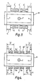
- the present invention is operated such that as shown in Figs.1 to 3, the electromagnetic agitating device 2 for use in generating a thrust force in a pulling direction of the slab S arranged at an inner wide surface 1 of a bending arc of the slab mold M in the bending type continuous casting machine is applied or both the electromagnetic agitating device 2 and an electromagnetic agitating device 2′ for use in generating a thrust force in the pulling direction of the slab S are applied, and the thrust force in the thrusting direction applied to the molten steel 5 by these electromagnetic agitating devices 2 and 2′ is substantially applied to range except a predetermined length L from the right and left side ends (narrow surfaces) 4 of the slab wide surface 3 to be casted toward the centeral part.
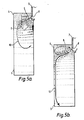
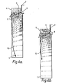
- an application of the thrust force up to the narrow surface 4 of the slab S causes an immersion depth of the molten steel flow 10 immersing into the slab S along the narrow surface 4 of the slab mold M to be further increased if the electromagnetic agitating device 2 is arranged in the slab mold M (fig.6(a)) as compared with the case in which the electromagnetic agitating device 2 is not arranged in the slab mold M, resulting in that the obstacles or bubbles such as argon gas enclosed in the molten steel flow 10 immerse deeply into the slab.
- a predetermined length L where the thrust force in the pulling direction of the aforesaid electromagnetic agitating device 2 may not apply is 50 mm or more and preferably 100 mm or more. If this length is less than 100 mm, an immersion depth of the molten steel flow 10 is not sufficiently restrcited and an effect of reducing obstacles in the slab or bubbles such as argon gas is eliminated.
- Figs.5 and 6 are symmetrical views as viewed from the wide surface, so that only their half sides will be illustrated.
- a total number of four units of linear motor type electromagnetic agitating devices 2 and 2′ are arranged at both sides of the inner wide surface 1 and the outer wide surface 1′ of the mold M at their symmetrial positions in width direction as shown in Fig.3 by applying a bending type continuous casting machine having a slab mold M of which width size can be varied in a thickness of 230 mm x a width of 800 to 1630 mm.
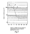
- Fig.7 shows a result in which obstacles of more than a size of 100 ⁇ m present between a position of 22 mm and a position of 52 mm from inside surface the slabs manufactured in this way were surveyed over an entire width of the slab.
- Fig. 7 11 denotes a rigid line showing a level of the number of typical obstacles in case of not applying the thrust force of the electromagnetic agitating device.
- 12 denotes a point for indicating the actual measured number of obstacles for every value L in case that the thrust force of the agitating device.
- a total number of eight linear motor tape electromagnetic agitating devices 2a, 2b, 2a′ and 2b′ were installed at both sides of the inner wide surface 1 and the outer wide surface 1′ of the casting mold M and at the right and left symmetrical positions in width direction by applying a bending type continuous casting machine having the slab casting mold with variable width of the same size as that of Example 1.
- the electromagnetic agitating devices 2a and 2a′ positioned at the casting mold narrow surface 4 sides in the width direction were positioned at a place from about 300 mm from the narrow surface under the maximum width (1630 mm) of the casting mold, and the electromagnetic agitating devices 2b and 2b′ positioned at the center of the casting mold were arranged at a position spaced apart by about 500 mm from the narrow surface thereof.
- this preferred embodiment means that even in case that a width of the casting mold is widely varied, if the electromagnetic agitating devices are divided into a plurality of segments at the narrow surface side and the central side of mold, these electromagnetic agitating devices are separately used in response to the width of the casting mold during casting operation to enable the thrust force applied in the drawing direction to be always acted upon except the predetermined range of the narrow surface side of the casting mold (in this case L ⁇ 50 mm).
- the electromagnetic agitating device 2 is divided into a plurality of segments 2a and 2b, and an immersing depth of the molten steel flow 10 immersing into the slab S can be positively restricted in correspondence with a wide width of the slab S to be casted by the casting mold M, thereby the number of obstacles in the slab can be positively reduced.
- Fig.8 is a right and left symmetrical view as viewed from a wide surface, so that only the left half of it is shown and illustrated.
- the present invention is not limited to the above-mentioned preferred embodiments, but a shielding plate is arranged between the electromagnetic agitating device 2 and the wall surface of the casting mold in such a way as it may be moved in rightward or leftward direction so as to control a thrust force of the electromagnetic agitating device 2 acting against the slab S.
- a total number of four linear motor type electromagnetic agitating devices 2 and 2′ were arranged at the right and left symmetrical positions in width directions of the inner and outer wide surfaces 1 and 1′ of the casting mold M by using a bending type continuous casting machine having a slab casting mold of a thickness of 230 mm x a width of 1230 mm.
- Each of the electromagnetic agitating devices was arranged such that a distance L between these side ends and the narrow surface of the casting mold equals to 130 mm and a thrust force in the drawing direction applied by these electromagnetic agitating devices (F) was varied to show various values, a low carbon aluminum killed steel (C: 0.04 to 0.05 %, Mn: 0.15 to 0.25 %, Al: 0.030 to 0.050 %) was casted into a slab having a width of 1230 mm under a drawing speed of 1.0 to 1.45 m/min.
- F B2 (N/m3) where, ⁇ : pole pitch (mm) ⁇ : specific resistance of molten steel ( ⁇ cm) f : frequency (Herz) B : magnetic flux density (Gauss)
- ⁇ pole pitch
- ⁇ cm specific resistance of molten steel
- f frequency
- B magnetic flux density (Gauss)
- Fig. 11 is a graph for showing a relation between a thrust force (F) and the number of obstacles in reference to a result of surveying the obstacles.
- the number of obstacles an index number expressed by a ratio in respect to the number when the agitation was not carried out was used.
- the thrust force (F) should be set within a range of 2500 to 11000 N/m3 and preferably 4500 to 9000 N/m3, and further most preferably, 5500 to 8000 N/m3 for the operation.
- the thrust force in the drawing direction of the electromagnetic agitating devices arranged at the inner wide surface or both inner and outer wide surfaces of the slab casting mold is acted toward the central part of the mold from the narrow surface of the casting mold in a range except the predetermined length, so that an immersing depth of the molten steel flow immersing into the slab along the narrow surface of the casting mold is restricted, the obstacles or bubbles such as argon gas are prevented from deeply immersing into the slab, resulting in that a high quality slab can be attained.
Landscapes
- Engineering & Computer Science (AREA)
- Mechanical Engineering (AREA)
- Continuous Casting (AREA)
Applications Claiming Priority (2)
| Application Number | Priority Date | Filing Date | Title |
|---|---|---|---|
| JP16487589 | 1989-06-27 | ||
| JP164875/89 | 1989-06-27 |
Publications (2)
| Publication Number | Publication Date |
|---|---|
| EP0405948A2 true EP0405948A2 (de) | 1991-01-02 |
| EP0405948A3 EP0405948A3 (en) | 1991-11-21 |
Family
ID=15801578
Family Applications (1)
| Application Number | Title | Priority Date | Filing Date |
|---|---|---|---|
| EP19900307038 Withdrawn EP0405948A3 (en) | 1989-06-27 | 1990-06-27 | Electromagnetic agitating method in mold of continuous casting of slab |
Country Status (4)
| Country | Link |
|---|---|
| US (1) | US5095969A (de) |
| EP (1) | EP0405948A3 (de) |
| JP (1) | JPH0390257A (de) |
| CA (1) | CA2019891A1 (de) |
Cited By (2)
| Publication number | Priority date | Publication date | Assignee | Title |
|---|---|---|---|---|
| EP0550785A1 (de) * | 1992-01-08 | 1993-07-14 | Nkk Corporation | Verfahren zum Stranggiessen |
| CN115194113A (zh) * | 2022-06-21 | 2022-10-18 | 首钢集团有限公司 | 一种板坯结晶器的调整方法 |
Families Citing this family (6)
| Publication number | Priority date | Publication date | Assignee | Title |
|---|---|---|---|---|
| DE69230666T2 (de) * | 1991-09-25 | 2000-06-08 | Kawasaki Steel Corp., Kobe | Verfahren zum stranggiessen von stahl unter verwendung von magnetfeldern |
| DE10158295B4 (de) * | 2001-11-23 | 2005-11-24 | Bramble-Trading Internacional Lda, Funchal | Strömungskörper |
| KR100376504B1 (ko) * | 1998-08-04 | 2004-12-14 | 주식회사 포스코 | 연속주조방법및이에이용되는연속주조장치 |
| JP4660038B2 (ja) * | 2001-09-27 | 2011-03-30 | 新日本製鐵株式会社 | 薄板用鋼板の溶製方法およびその鋳片 |
| JP5310205B2 (ja) * | 2009-04-06 | 2013-10-09 | 新日鐵住金株式会社 | 連続鋳造設備における鋳型内の溶鋼流動制御方法 |
| CN104128588B (zh) * | 2014-06-25 | 2016-02-24 | 西安交通大学 | 一种复合轴瓦的半固态连铸与电磁成形连接装置 |
Family Cites Families (4)
| Publication number | Priority date | Publication date | Assignee | Title |
|---|---|---|---|---|
| JPS6037251A (ja) * | 1983-08-11 | 1985-02-26 | Kawasaki Steel Corp | 連続鋳造鋳型内溶鋼の電磁撹拌方法 |
| JPS61255749A (ja) * | 1985-05-08 | 1986-11-13 | Kawasaki Steel Corp | スラブ連続鋳造鋳片内の非金属介在物の減少方法 |
| JPS63119959A (ja) * | 1986-11-06 | 1988-05-24 | Kawasaki Steel Corp | 連続鋳造用浸漬ノズルの吐出流制御装置 |
| JPS63154246A (ja) * | 1986-12-18 | 1988-06-27 | Kawasaki Steel Corp | 静磁場を用いる鋼の連続鋳造方法 |
-
1990
- 1990-06-22 JP JP2164685A patent/JPH0390257A/ja active Pending
- 1990-06-26 CA CA002019891A patent/CA2019891A1/en not_active Abandoned
- 1990-06-27 US US07/544,668 patent/US5095969A/en not_active Expired - Fee Related
- 1990-06-27 EP EP19900307038 patent/EP0405948A3/en not_active Withdrawn
Cited By (3)
| Publication number | Priority date | Publication date | Assignee | Title |
|---|---|---|---|---|
| EP0550785A1 (de) * | 1992-01-08 | 1993-07-14 | Nkk Corporation | Verfahren zum Stranggiessen |
| CN115194113A (zh) * | 2022-06-21 | 2022-10-18 | 首钢集团有限公司 | 一种板坯结晶器的调整方法 |
| CN115194113B (zh) * | 2022-06-21 | 2023-10-13 | 首钢集团有限公司 | 一种板坯结晶器的调整方法 |
Also Published As
| Publication number | Publication date |
|---|---|
| JPH0390257A (ja) | 1991-04-16 |
| EP0405948A3 (en) | 1991-11-21 |
| CA2019891A1 (en) | 1990-12-27 |
| US5095969A (en) | 1992-03-17 |
Similar Documents
| Publication | Publication Date | Title |
|---|---|---|
| EP0321206A1 (de) | Tauchrohr zum Stranggiessen | |
| EP0550785B1 (de) | Verfahren zum Stranggiessen | |
| EP0405948A2 (de) | Elektromagnetisches Rührverfahren in Kokillen zum Stranggiessen von Brammen | |
| EP3760337A1 (de) | Einrichtung zum formgiessen | |
| EP0707909B1 (de) | Verfahren zur steuerung des flusses in einer giessform mittels dc-magnetischen feldern | |
| EP0265235B1 (de) | Stranggiessen von Verbundmetall | |
| DE69605608T2 (de) | Verfahren und Vorrichtung zum Erzeugen von Schwingungen in einer Metallschmelze beim Stranggiessen mittels Doppelwalzen | |
| EP0445328B1 (de) | Verfahren für das Stranggiessen von Stahl | |
| JPS6328702B2 (de) | ||
| JPH0555220B2 (de) | ||
| US4529030A (en) | Electromagnetic stirring method in horizontal continuous casting process | |
| JP3300619B2 (ja) | 介在物の少ない鋳片の連続鋳造方法 | |
| JP2633764B2 (ja) | 連続鋳造モールド内溶鋼流動制御方法 | |
| JPS5976647A (ja) | 連続鋳造における鋳込み溶鋼の撹拌方法および装置 | |
| JP3408374B2 (ja) | 連続鋳造方法 | |
| JP2607335B2 (ja) | 連続鋳造鋳型内溶鋼の流動制御装置 | |
| JP2607334B2 (ja) | 連続鋳造鋳型内溶鋼の流動制御装置 | |
| SU1428181A3 (ru) | Способ электромагнитного перемешивани расплавленной стали при непрерывном литье пр моугольных заготовок | |
| JP3399627B2 (ja) | 直流磁界による鋳型内溶鋼の流動制御方法 | |
| JPH06606A (ja) | 連続鋳造鋳型内溶鋼の流動制御装置 | |
| GB2041803A (en) | Electromagnetic casting apparatus and process | |
| JP2633769B2 (ja) | 連続鋳造モールド内溶鋼流動制御方法 | |
| JP2607333B2 (ja) | 連続鋳造鋳型内溶鋼の流動制御装置 | |
| JP2633765B2 (ja) | 連続鋳造モールド内溶鋼流動制御方法 | |
| KR960003711B1 (ko) | 연속 슬랩 주조방법 |
Legal Events
| Date | Code | Title | Description |
|---|---|---|---|
| PUAI | Public reference made under article 153(3) epc to a published international application that has entered the european phase |
Free format text: ORIGINAL CODE: 0009012 |
|
| 17P | Request for examination filed |
Effective date: 19900717 |
|
| AK | Designated contracting states |
Kind code of ref document: A2 Designated state(s): AT DE FR GB |
|
| PUAL | Search report despatched |
Free format text: ORIGINAL CODE: 0009013 |
|
| AK | Designated contracting states |
Kind code of ref document: A3 Designated state(s): AT DE FR GB |
|
| 17Q | First examination report despatched |
Effective date: 19930810 |
|
| STAA | Information on the status of an ep patent application or granted ep patent |
Free format text: STATUS: THE APPLICATION IS DEEMED TO BE WITHDRAWN |
|
| 18D | Application deemed to be withdrawn |
Effective date: 19931221 |