EP0405083A1 - Endquerdichtung für eine durchbiegungssteuerbare Walze - Google Patents
Endquerdichtung für eine durchbiegungssteuerbare Walze Download PDFInfo
- Publication number
- EP0405083A1 EP0405083A1 EP90107602A EP90107602A EP0405083A1 EP 0405083 A1 EP0405083 A1 EP 0405083A1 EP 90107602 A EP90107602 A EP 90107602A EP 90107602 A EP90107602 A EP 90107602A EP 0405083 A1 EP0405083 A1 EP 0405083A1
- Authority
- EP
- European Patent Office
- Prior art keywords
- crosshead
- ring
- end cross
- sliding
- roller
- Prior art date
- Legal status (The legal status is an assumption and is not a legal conclusion. Google has not performed a legal analysis and makes no representation as to the accuracy of the status listed.)
- Granted
Links
- 239000012530 fluid Substances 0.000 claims abstract description 10
- -1 polytetrafluoroethylene Polymers 0.000 claims description 3
- 229920001343 polytetrafluoroethylene Polymers 0.000 claims description 3
- 239000004810 polytetrafluoroethylene Substances 0.000 claims description 3
- 239000000463 material Substances 0.000 claims description 2
- 230000002093 peripheral effect Effects 0.000 claims description 2
- 230000000149 penetrating effect Effects 0.000 abstract description 2
- 238000007789 sealing Methods 0.000 description 6
- 230000000694 effects Effects 0.000 description 2
- 239000007788 liquid Substances 0.000 description 2
- 230000006835 compression Effects 0.000 description 1
- 238000007906 compression Methods 0.000 description 1
- 239000000256 polyoxyethylene sorbitan monolaurate Substances 0.000 description 1
Images
Classifications
-
- B—PERFORMING OPERATIONS; TRANSPORTING
- B21—MECHANICAL METAL-WORKING WITHOUT ESSENTIALLY REMOVING MATERIAL; PUNCHING METAL
- B21B—ROLLING OF METAL
- B21B27/00—Rolls, roll alloys or roll fabrication; Lubricating, cooling or heating rolls while in use
- B21B27/02—Shape or construction of rolls
- B21B27/03—Sleeved rolls
- B21B27/05—Sleeved rolls with deflectable sleeves
- B21B27/055—Sleeved rolls with deflectable sleeves with sleeves radially deflectable on a stationary beam by means of hydraulic supports
-
- B—PERFORMING OPERATIONS; TRANSPORTING
- B65—CONVEYING; PACKING; STORING; HANDLING THIN OR FILAMENTARY MATERIAL
- B65H—HANDLING THIN OR FILAMENTARY MATERIAL, e.g. SHEETS, WEBS, CABLES
- B65H27/00—Special constructions, e.g. surface features, of feed or guide rollers for webs
-
- D—TEXTILES; PAPER
- D21—PAPER-MAKING; PRODUCTION OF CELLULOSE
- D21G—CALENDERS; ACCESSORIES FOR PAPER-MAKING MACHINES
- D21G1/00—Calenders; Smoothing apparatus
- D21G1/02—Rolls; Their bearings
- D21G1/0206—Controlled deflection rolls
- D21G1/0213—Controlled deflection rolls with deflection compensation means acting between the roller shell and its supporting member
- D21G1/022—Controlled deflection rolls with deflection compensation means acting between the roller shell and its supporting member the means using fluid pressure
-
- F—MECHANICAL ENGINEERING; LIGHTING; HEATING; WEAPONS; BLASTING
- F16—ENGINEERING ELEMENTS AND UNITS; GENERAL MEASURES FOR PRODUCING AND MAINTAINING EFFECTIVE FUNCTIONING OF MACHINES OR INSTALLATIONS; THERMAL INSULATION IN GENERAL
- F16C—SHAFTS; FLEXIBLE SHAFTS; ELEMENTS OR CRANKSHAFT MECHANISMS; ROTARY BODIES OTHER THAN GEARING ELEMENTS; BEARINGS
- F16C13/00—Rolls, drums, discs, or the like; Bearings or mountings therefor
- F16C13/02—Bearings
- F16C13/022—Bearings supporting a hollow roll mantle rotating with respect to a yoke or axle
- F16C13/024—Bearings supporting a hollow roll mantle rotating with respect to a yoke or axle adjustable for positioning, e.g. radial movable bearings for controlling the deflection along the length of the roll mantle
- F16C13/026—Bearings supporting a hollow roll mantle rotating with respect to a yoke or axle adjustable for positioning, e.g. radial movable bearings for controlling the deflection along the length of the roll mantle by fluid pressure
-
- F—MECHANICAL ENGINEERING; LIGHTING; HEATING; WEAPONS; BLASTING
- F16—ENGINEERING ELEMENTS AND UNITS; GENERAL MEASURES FOR PRODUCING AND MAINTAINING EFFECTIVE FUNCTIONING OF MACHINES OR INSTALLATIONS; THERMAL INSULATION IN GENERAL
- F16J—PISTONS; CYLINDERS; SEALINGS
- F16J15/00—Sealings
- F16J15/16—Sealings between relatively-moving surfaces
- F16J15/34—Sealings between relatively-moving surfaces with slip-ring pressed against a more or less radial face on one member
- F16J15/3404—Sealings between relatively-moving surfaces with slip-ring pressed against a more or less radial face on one member and characterised by parts or details relating to lubrication, cooling or venting of the seal
- F16J15/3408—Sealings between relatively-moving surfaces with slip-ring pressed against a more or less radial face on one member and characterised by parts or details relating to lubrication, cooling or venting of the seal at least one ring having an uneven slipping surface
- F16J15/3412—Sealings between relatively-moving surfaces with slip-ring pressed against a more or less radial face on one member and characterised by parts or details relating to lubrication, cooling or venting of the seal at least one ring having an uneven slipping surface with cavities
- F16J15/342—Sealings between relatively-moving surfaces with slip-ring pressed against a more or less radial face on one member and characterised by parts or details relating to lubrication, cooling or venting of the seal at least one ring having an uneven slipping surface with cavities with means for feeding fluid directly to the face
-
- B—PERFORMING OPERATIONS; TRANSPORTING
- B65—CONVEYING; PACKING; STORING; HANDLING THIN OR FILAMENTARY MATERIAL
- B65H—HANDLING THIN OR FILAMENTARY MATERIAL, e.g. SHEETS, WEBS, CABLES
- B65H2404/00—Parts for transporting or guiding the handled material
- B65H2404/10—Rollers
- B65H2404/13—Details of longitudinal profile
- B65H2404/137—Means for varying longitudinal profiles
- B65H2404/1372—Means for varying longitudinal profiles anti-deflection
Definitions
- the invention relates to an end cross seal of the type corresponding to the preamble of claim 1.
- Such an end cross seal serves to seal the space between the rotating hollow roller and the fixed crosshead in the axial direction to the outside against an internal pressure.
- the internal pressure can occur if the hydraulic support device consists of a semi-cylindrical shell-shaped chamber filled with hydraulic fluid, which is separated from the remaining space by the end cross seals and longitudinal seals attached to both sides of the cross head, as is the case with the JP-GM-AS on which the preamble is based 62-17520 is the case.
- a similar end cross seal is also shown in DE-PS 20 25 777.
- the transverse end seal limited by a partitioned longitudinal seals semi-cylindrical cup-shaped so-called S-roll chamber
- the transverse end seal extends over approximately 180 ° in the circumferential direction.
- the pressure in the S-roll chamber is modified by sealing members which omit zones of lower pressure.
- the pressure against which the end cross seal is to seal is several 10 bar.
- the peripheral speed on the abutting sliding surfaces can be up to 1000 m / min, and finally the hydraulic pressure fluid can have a temperature of 250 o C or more. It has been found that under these difficult conditions, the pressure fluid on the pressure side tends to penetrate radially from the outside from the sliding ring and to lift it off the stationary counter ring, which naturally impairs the sealing effect.
- the invention has for its object to suppress this phenomenon. This object is achieved by the invention reproduced in claim 1.
- the slide ring can be designed and sealed in detail in the manner that can be taken from claim 2. It has been found that a perfect seal of the slide ring against the crosshead, in contrast to which it must be displaceable in the event of deflections of the hollow roller and in particular the crosshead, can be achieved in this way.
- the ring which rests against the approach of the slide ring from the inside, can in particular consist of polytetrafluoroethylene, because this is a material which is easy to slide and at the same time to a certain extent conformable.
- connection of the groove to the low-pressure side can be formed in this embodiment according to claim 4 by a channel which passes essentially axially through the slide ring, generally through a corresponding bore.
- the chamber is divided into several individual chambers in the circumferential direction and gaps remain between them, there is another possibility of establishing a connection between the groove and the low-pressure side, in the design reproduced in claim 5.
- Channels leading radially inwards from a groove of an end transverse seal are known per se from DE-OS 38 13 596, which belongs to the prior art but is not prepublished. However, this is not a mechanical seal in which an axial pressure takes place.
- the seal known from DE-OS 38 13 596 is rather hydraulically pressed radially against the inner circumference of the hollow roller, and the radial channels serve to branch off the pressure required for hydraulic relief of the sliding surfaces.
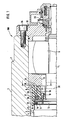
- the roller designated 100 as a whole in FIG. 1 comprises an non-rotatable crosshead 1, around which a hollow roller 2 rotates, which forms the working roller periphery 3 and which leaves its inner periphery 4 at a distance from the outer periphery 5 of the crosshead.
- the hollow roller 2 is supported at the ends on spherical roller bearings 6 on the crosshead 1.
- a counter ring 8 is clamped, which rotates with the hollow roller 2, surrounds the crosshead 1 and, on the side facing inwards, provides a sliding surface 9 perpendicular to the axis of the hollow roller 2 which rests on the crosshead 1, which is movable relative to it within a certain range but is otherwise stationary, in a sealing manner.
- the slide ring 10 has a substantially rectangular cross section and is arranged in front of a diameter step 11 of the crosshead. It overlaps the diameter step 11 with an externally provided axial shoulder 12. In the area in which the shoulder 12 overlaps the diameter step 11, a radially outwardly open circumferential groove 13 is provided in the groove, on the bottom of which an O-ring 14 and above Ring 15 of substantially rectangular cross-section made of polytetrafluoroethylene are arranged.
- the ring 15 lies with its outer side sealingly against the inner circumference 16 of the shoulder 12. There is little play between the inner circumference 16 and the adjacent outer circumference of the crosshead 1, so that the sliding ring 10 can shift somewhat relative to the crosshead 1 in order to take account of the deflection of the crosshead 1 when the roller 100 is loaded.
- the slide ring 10 is pressed against the counter ring 8 by axial helical compression springs 17 lying in front of the diameter step 11 and prevented from rotating by screws 18 distributed over the circumference.
- the sliding ring 10 On the side facing the sliding surface, the sliding ring 10 has a plurality of chambers 19, which together take up almost the entire circumference, and which, with the high-pressure space 20 between the inner circumference 4 of the hollow roller 2 and the outer circumference 5 of the crosshead 1, each have one in Fig. 1 are only schematically indicated throttled channel 21 in connection.
- the channel 21 consists of an axially extending bore 22 which opens into the chamber 19 and is closed at the other end by a plug 24. Between the stopper 24 and the chamber 19 there is a radial bore 23 which communicates with the pressurized intermediate space 20 and which brings in the pressure fluid which passes throttled into the chamber 19 through a throttle insert 25 provided in the bore 22.
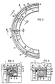
- FIG. 2 in the exemplary embodiment there are six chambers 19 distributed over the circumference, each of which is connected to the intermediate space 20 by a channel 21.
- a 360 ° continuous narrow groove 30 of, for example, 3 mm depth and width is attached, which has a or several channels 26 only indicated in FIG. 1 and shown in detail in FIG. 4 is connected to the low-pressure side, ie in the exemplary embodiment to the other end face 36 of the slide ring 10 which is remote from the sliding surface 9 and which is separated from the intermediate space carrying the high pressure 20 is separated by the pair of sealing rings 14, 15.
- the end face 36 has an axial distance from the diameter step 11.
- the inner circumference 37 of the slide ring 10 has a radial distance from the adjacent area of the crosshead 1. Hydraulic fluid passing through the channel 26 can therefore flow through these spacing spaces. In this way, at the point 27 in FIG. 4, hydraulic fluid penetrating into the intermediate space 20 under the high pressure is immediately drained off before it can lift the sliding ring 10 off the sliding surface 9, as a result of which the perfect sealing and sliding effect on the sliding ring 10 in the region the chambers 19 remains unaffected.
- the leakage liquid which has passed from the high-pressure space 20 on the sliding surface 9 and on the seal 15 can be sucked off through a channel 28.
- FIG. 2 An alternative to the channels 26 is indicated in FIG. 2, which is, however, only possible if the chamber 19 does not pass over the circumference, but rather individual chambers 19 are present, each of which occupy only one segment of the circumference and a spacing space 31 between them leave.
- a radial groove 32 which is open towards the sliding surface 9, can be carried out from the circumferential groove 30 to the inside, which is also able to relieve the pressure in the groove 30 by providing access to the low-pressure side .
- the adjacent chambers 19 must not be cut, i.e. they must be closed in all directions in the sliding plane 9, otherwise they cannot perform their function.
- the hollow roller 2 is closed at the end by a cover 33 which is connected to the hollow roller 2 by means of screws 34.
- the cover 33 which rotates with the hollow roller 2, is sealed off from the crosshead 1 by a further mechanical seal 35, which, however, does not have to seal against particularly high pressure, but is only intended to prevent pressure fluid from escaping from the roller.
Landscapes
- Engineering & Computer Science (AREA)
- General Engineering & Computer Science (AREA)
- Physics & Mathematics (AREA)
- Mechanical Engineering (AREA)
- Fluid Mechanics (AREA)
- Geometry (AREA)
- Rolls And Other Rotary Bodies (AREA)
- Sealing With Elastic Sealing Lips (AREA)
- Mechanical Sealing (AREA)
- Sealing Devices (AREA)
Abstract
Description
- Die Erfindung bezieht sich auf eine Endquerdichtung der dem Oberbegriff des Anspruchs 1 entsprechenden Art.
- Eine solche Endquerdichtung dient dazu, den Zwischenraum zwischen der umlaufenden Hohlwalze und dem feststehenden Querhaupt in Achsrichtung nach außen gegen einen Innendruck abzudichten. Der Innendruck kann zustande kommen, wenn die hydraulische Stützeinrichtung aus einer mit Druckflüssigkeit gefüllten halbzylinderschalenförmigen Kammer besteht, die durch die Endquerdichtungen und zu beiden Seiten des Querhaupts angebrachte Längsdichtungen von dem übrigen Zwischenraum abgeteilt ist, wie es bei der dem Oberbegriff zugrundeliegenden JP-GM-AS 62-17520 der Fall ist. Eine ähnliche Endquerdichtung ist auch in der DE-PS 20 25 777 wiedergegeben. In den vorgenannten Fällen, in denen die Endquerdichtung eine durch Längsdichtungen abgeteilte halbzylinderschalenförmige sogenannte S-Walzenkammer begrenzt, erstreckt sich die Endquerdichtung über etwa 180o in Umfangsrichtung. Dies gilt auch für den Fall der DE-PS 30 03 395, in der der Druck in der S-Walzenkammer durch Dichtungsglieder modifiziert wird, die Zonen niedrigeren Drucks aussparen.
- Es gibt aber auch Fälle, in denen der gesamte Zwischenraum zwischen Hohlwalze und Querhaupt über 360o mit Druckflüssigkeit ausgefüllt ist, wie es in der DE-OS 36 40 902 dargestellt ist. In diesen Fällen erstreckt sich natürlich auch die Endquerdichtung über 360o.
- In vielen Fällen beträgt der Druck, gegen den die Endquerdichtung abdichten soll, mehrere 10 bar. Die Umfangsgeschwindigkeit an den aneinander anliegenden Gleitflächen kann bis zu 1000 m/min betragen, und es kann schließlich die hydraulische Druckflüssigkeit eine Temperatur von 250oC oder mehr aufweisen. Es wurde gefunden, daß unter diesen erschwerten Bedingungen die Druckflüssigkeit auf der Druckseite die Tendenz hat, den Gleitring radial von außen zu unterwandern und von dem feststehenden Gegenring abzuheben, wodurch die Dichtwirkung naturgemäß beeinträchtigt wird.
- Der Erfindung liegt die Aufgabe zugrunde, diese Erscheinung zu unterdrücken. Diese Aufgabe wird durch die in Anspruch 1 wiedergegebene Erfindung gelöst.
- Es ist hierdurch erreicht, daß die an der Gleitfläche von der Druckseite her radial von außen eingedrungenen Flüssigkeitsmengen sogleich zu Niederdruckseite abgeleitet werden und sich in der Gleitfläche kein abhebender Druck mehr aufbauen kann. Der Gleitring liegt zu beiden Seiten der Kammer, die zur Entlastung des unter dem hohen Druck auf der Überdruckseite gegen die Gleitfläche angepreßten Gleitrings dient, einwandfrei an und vermag so seine Dichtfunktion einwandfrei auszuüben.
- Der Gleitring kann im einzelnen in der aus Anspruch 2 entnehmbaren Weise ausgebildet und abgedichtet sein. Es wurde gefunden, daß sich auf diese Weise eine einwandreie Abdichtung des Gleitrings gegen das Querhaupt, demgegenüber er ja bei Durchbiegungen der Hohlwalze und insbesondere des Querhaupts verlagerbar sein muß, zu erzielen ist.
- Der gegen den Ansatz des Gleitrings von innen anliegende Ring kann insbesonders aus Polytetrafluoräthylen bestehen, weil dies ein gleitgünstiges und gleichzeitig noch in einem gewissen Grade anschmiegsames Material ist.
- Die Verbindung der Nut mit der Niederdruckseite kann bei dieser Ausführungsform gemäß Anspruch 4 durch einen Kanal gebildet sein, der im wesentlichen axial durch den Gleitring hindurchführt, im allgemeinen also durch eine entsprechende Bohrung.
- Wenn die Kammer in Umfangsrichtung in mehrere Einzelkammern unterteilt ist und dazwischen Zwischenräume verbleiben, besteht eine andere Möglichkeit, eine Verbindung der Nut mit der Niederdruckseite herzustellen, in der in Anspruch 5 wiedergegebenen Gestaltung.
- Radial von einer Nut einer Endquerdichtung nach innen führende Kanäle sind für sich genommen aus der zum Stand der Technik gehörenden, jedoch nicht vorveröffentlichten DE-OS 38 13 596 bekannt. Hierbei handelt es sich aber nicht um eine Gleitringdichtung, bei der eine axiale Anpressung stattfindet. Die aus der DE-OS 38 13 596 bekannte Dichtung wird vielmehr hydraulisch radial gegen den Innenumfang der Hohlwalze angepreßt, und die radialen Kanäle dienen dazu, den für eine hydraulische Entlastung der Gleitflächen notwendigen Druck abzuzweigen.
- In der Zeichnung sind Ausführungsbeispiele der Erfindung dargestellt.
- Fig. 1 zeigt einen Teillängsschnitt durch das rechte Ende einer durchbiegungssteuerbaren Walze mit der erfindungsgemäßen Endquerdichtung;
- Fig. 2 zeigt eine Teilansicht eines über 180o gehenden Bereichs der Endquerdichtung gemäß der Linie II-II in Fig. 1;
- Fig. 3 und 4 zeigen Schnittansichten nach den Linien III-III und IV-IV in Fig. 2.
- Die in Fig. 1 als Ganzes mit 100 bezeichnete Walze umfaßt ein undrehbares Querhaupt 1, um welches eine Hohlwalze 2 umläuft, die den arbeitenden Walzenumfang 3 bildet und die mit ihrem Innenumfang 4 Abstand von dem Außenumfang 5 des Querhauptes beläßt. Die Hohlwalze 2 ist an den Enden über Pendelrollenlager 6 auf dem Querhaupt 1 gelagert. Zwischen dem Pendelrollenlager 6 und einer Stufe 7 am Innenumfang 4 der Hohlwalze 2 ist ein Gegenring 8 eingespannt, der mit der Hohlwalze 2 umläuft, das Querhaupt 1 umgibt und an der nach innen gewandten Seite eine zur Achse der Hohlwalze 2 senkrechte Gleitfläche 9 darbietet, gegen die ein am Querhaupt 1 abgestützter, gegenüber diesem in einem gewissen Rahmen beweglicher,ansonsten aber feststehender Gleitring 10 dichtend anliegt.
- Der Gleitring 10 hat einen im wesentlichen rechteckigen Querschnitt und ist vor einer Durchmesserstufe 11 des Querhauptes angeordnet. Er übergreift mit einem außen vorgesehenen axialen Ansatz 12 die Durchmesserstufe 11. In dem Bereich, in dem der Ansatz 12 die Durchmesserstufe 11 übergreift, ist in dieser eine radial nach außen offene Umfangsnut 13 angebracht, auf deren Grund ein O-Ring 14 und darüber ein Ring 15 von im wesentlichen rechteckigem Querschnitt aus Polytetrafluoräthylen angeordnet sind. Der Ring 15 liegt mit seiner Außenseite dichtend am Innenumfang 16 des Ansatzes 12 an. Zwischen dem Innenumfang 16 und dem benachbarten Außenumfang des Querhauptes 1 besteht ein geringes Spiel, so daß sich der Gleitring 10 gegenüber dem Querhaupt 1 etwas verlagern kann, um der Durchbiegung des Querhaupts 1 bei Belastung der Walze 100 Rechnung zu tragen.
- Der Gleitring 10 wird durch axiale, sich vor die Durchmesserstufe 11 legende Schraubendruckfedern 17 gegen den Gegenring 8 angedrückt und durch über den Umfang verteilte Schrauben 18 an einer Drehung gehindert.
- Auf der der Gleitfläche , zugewandten Seite weist der Gleitring 10 mehrere, zusammen fast den ganzen Umfang einnehmende Kammern 19 auf, die mit dem einen hohen Druck führenden Zwischenraum 20 zwischen dem Innenumfang 4 der Hohlwalze 2 und dem Außenumfang 5 des Querhauptes 1 über jeweils einen in Fig. 1 nur schematisch angedeuteten gedrosselten Kanal 21 in Verbindung stehen.
- Die Ausführung im einzelnen ist aus den Fig. 2 und 3 ersichtlich. Der Kanal 21 besteht aus einer in Achsrichtung verlaufenden Bohrung 22, die in die Kammer 19 mündet und am anderen Ende durch einen Stopfen 24 verschlossen ist. Zwischen dem Stopfen 24 und der Kammer 19 ist eine radiale Bohrung 23 angebracht, die mit dem unter Druck stehenden Zwischenraum 20 in Verbindung steht und die Druckflüssigkeit heranführt, die durch einen in der Bohrung 22 angebrachten Drosseleinsatz 25 gedrosselt in die Kammer 19 übertritt.
- Wie aus Fig. 2 ersichtlich ist, sind in dem Ausführungsbeispiel sechs über den Umfang verteilte Kammern 19 vorhanden, die durch jeweils einen Kanal 21 mit dem Zwischenraum 20 in Verbindung stehen.
- Radial außerhalb der Kammern 19 ist in einer der Gleitfläche 9 zugewandten Stirnfläche des Gleitringes 10 nahe dem äußeren Rand der Gleitfläche 9 und nur wenige Millimeter von diesem entfernt eine über 360o durchgehende schmale Nut 30 von beispielsweise 3 mm Tiefe und Breite angebracht, die über einen oder mehrere in Fig. 1 nur angedeutete und in Fig. 4 im einzelnen ersichtliche Kanäle 26 mit der Niederdruckseite in Verbindung steht, d.h. in dem Ausführungsbeispiel mit der der Gleitfläche 9 abgelegenen anderen Stirnseite 36 des Gleitrings 10, die von dem den hohen Druck führenden Zwischenraum 20 durch das Dichtungsringpaar 14,15 getrennt ist. Die Stirnfläche 36 hat axialen Abstand von der Durchmesserstufe 11. Ebenso hat der Innenumfang 37 des Gleitrings 10 radialen Abstand von dem benachbarten Bereich des Querhaupts 1. Durch den Kanal 26 übertretende Druckflüssigkeit kann also durch diese Abstandsräume abströmen. Auf diese Weise wird an der Stelle 27 in Fig. 4 unter dem hohen Druck in den Zwischenraum 20 eindringende Druckflüssigkeit sogleich abgeleitet, bevor sie den Gleitring 10 von der Gleitfläche 9 abheben kann, wodurch die einwandfreie Dicht- und Gleitwirkung am dem Gleitring 10 im Bereich der Kammern 19 unbeeinträchtigt bleibt.
- Die an der Gleitfläche 9 und an der Dichtung 15 aus dem unter hohem Druck stehenden Zwischenraum 20 übergetretene Leckageflüssigkeit kann durch einen Kanal 28 abgesaugt werden.
- In Fig. 2 ist eine Alternative zu den Kanälen 26 angedeutet, die allerdings nur möglich ist, wenn die Kammer 19 nicht über den Umfang durchgeht, sondern einzelne Kammern 19 vorhanden sind, die jeweils nur ein Segment des Umfangs einnehmen und zwischen sich einen Abstandsraum 31 belassen. Durch diesen Abstandsraum kann eine radiale Nut 32, die gegen die Gleitfläche 9 hin offen ist, von der Umfangsnut 30 ausgehend bis nach innen durchgeführt sein, die ebenfalls den Druck in der Nut 30 abzubauen in der Lage ist, indem sie einen Zugang zur Niederdruckseite schafft. Die benachbarten Kammern 19 dürfen aber nicht angeschnitten werden, d.h. sie müssen in der Gleitebene 9 in allen Richtungen geschlossen sein, da sie sonst ihre Funktion nicht ausüben können.
- Die Hohlwalze 2 ist am Ende durch einen Deckel 33 abgeschlossen, der mittels Schrauben 34 mit der Hohlwalze 2 verbunden ist. Der Deckel 33, der mit der Hohlwalze 2 umläuft, ist gegenüber dem Querhaupt 1 durch eine weitere Gleitringdichtung 35 abgedichtet, die aber nicht gegen besonders hohen Druck abdichten muß, sondern nur den Austritt von Druckflüssigkeit aus der Walze verhindern soll.
Claims (5)
mit einer den arbeitenden Walzenumfang bildenden umlaufenden Hohlwalze und einem diese der Länge nach durchgreifenden, rundum Abstand vom Innenumfang der Hohlwalze belassenden undrehbaren Querhaupt
und mit einer gegen den Innenumfang der Hohlwalze wirkenden, am Querhaupt angeordneten hydraulischen Stützeinrichtung,
wobei die Endquerdichtung jeweils an einem Ende der Hohlwalze angeordnet ist und den Zwischenraum zwischen Hohlwalze und Querhaupt gegen den dort herrschenden Druck nach außen abdichtet
und durch eine Gleitringdichtung gebildet ist, deren in einer zur Achse der Walze senkrechten Gleitebene angeordneter, in Richtung der Achse beweglicher Gleitring mindestens eine gegen die Gleitfläche offene, in Umfangsrichtung verlaufende, in jeder zur Gleitebene parallelen Richtung geschlossene Kammer aufweist, zu der Druckflüssigkeit aus dem Zwischenraum zwischen Hohlwalze und Querhaupt Zutritt hat,
dadurch gekennzeichnet,
daß radial außerhalb der Kammer (19) eine über die Erstreckung der Endquerdichtung (8,10) in Umfangsrichtung verlaufende, gegen die Gleitfläche (9) offene Nut (30) vorgesehen ist, die mit der Niederdruckseite in Verbindung steht.
Applications Claiming Priority (2)
| Application Number | Priority Date | Filing Date | Title |
|---|---|---|---|
| DE3919208A DE3919208C1 (de) | 1989-06-13 | 1989-06-13 | |
| DE3919208 | 1989-06-13 |
Publications (2)
| Publication Number | Publication Date |
|---|---|
| EP0405083A1 true EP0405083A1 (de) | 1991-01-02 |
| EP0405083B1 EP0405083B1 (de) | 1993-08-25 |
Family
ID=6382625
Family Applications (1)
| Application Number | Title | Priority Date | Filing Date |
|---|---|---|---|
| EP90107602A Expired - Lifetime EP0405083B1 (de) | 1989-06-13 | 1990-04-21 | Endquerdichtung für eine durchbiegungssteuerbare Walze |
Country Status (10)
| Country | Link |
|---|---|
| US (1) | US5119542A (de) |
| EP (1) | EP0405083B1 (de) |
| JP (1) | JPH0646045B2 (de) |
| CN (1) | CN1017178B (de) |
| BR (1) | BR9002517A (de) |
| CA (1) | CA2018765C (de) |
| DD (1) | DD295214A5 (de) |
| DE (2) | DE3919208C1 (de) |
| FI (1) | FI107637B (de) |
| RU (1) | RU1838683C (de) |
Cited By (2)
| Publication number | Priority date | Publication date | Assignee | Title |
|---|---|---|---|---|
| EP0503381A1 (de) * | 1991-03-08 | 1992-09-16 | Voith Sulzer Finishing GmbH | Durchbiegungssteuerbare und beheizbare Walze |
| EP2362122A3 (de) * | 2010-02-24 | 2011-10-12 | KSB Aktiengesellschaft | Gleitringdichtung und Verfahren zur Optimierung von deren Betriebsverhalten |
Families Citing this family (10)
| Publication number | Priority date | Publication date | Assignee | Title |
|---|---|---|---|---|
| JP3160397B2 (ja) * | 1991-11-08 | 2001-04-25 | ヨット・エム・フォイト・ゲーエムベーハー | 別体をなす外皮及びロールコアを有するロール |
| US5242361A (en) * | 1992-11-17 | 1993-09-07 | Beloit Technologies, Inc. | Roller mechanism for axially locating the shell of a self-loading controlled deflection roll |
| JPH07176484A (ja) * | 1993-06-28 | 1995-07-14 | Applied Materials Inc | 窒化アルミニューム面を有するサセプタをサセプタの浄化後珪化タングステンで処理することによって半導体ウエハ上に珪化タングステンを一様に堆積する方法 |
| DE19705638A1 (de) * | 1997-02-14 | 1998-09-03 | Kuesters Eduard Maschf | Walzvorrichtung für die Druckbehandlung von Warenbahnen |
| US6004249A (en) * | 1998-07-13 | 1999-12-21 | Valmet Corporation | Slide disc seal arrangement for a roll of a paper making or finishing machine or the like |
| JP3790161B2 (ja) | 1999-07-13 | 2006-06-28 | 株式会社アマダエンジニアリングセンター | 板金曲げシステム及びその制御データ作成方法 |
| DE102006024832B4 (de) * | 2006-05-24 | 2013-07-18 | Andritz Küsters Gmbh | Durchbiegungssteuerbare Walze |
| CN101158405B (zh) * | 2007-06-21 | 2010-04-21 | 丹东克隆集团有限责任公司 | 径向双端面机械密封装置 |
| DE102010024291B4 (de) * | 2010-04-23 | 2013-04-18 | Carl Freudenberg Kg | Gleitringdichtung mit rotierendem Gegenring mit exakt definierter Einspannung |
| DE102019205894A1 (de) * | 2019-04-25 | 2020-10-29 | Robert Bosch Gmbh | Ventildeckel für ein Mehr-Wege-Einbauventil, insbesondere für ein 2-Wege-Einbauventil |
Citations (3)
| Publication number | Priority date | Publication date | Assignee | Title |
|---|---|---|---|---|
| DE2025777A1 (de) * | 1969-06-03 | 1970-12-17 | Usm Corp., Flemington, N.J. Und Boston, Mass. (V.St.A.) | Deflektionsrolle mit hydrostatischer Gleitflächendichtung |
| DE3128140C2 (de) * | 1981-07-16 | 1983-12-15 | Küsters, Eduard, 4150 Krefeld | Walze |
| DE3843434C1 (de) * | 1988-12-23 | 1990-04-19 | Eduard Kuesters, Maschinenfabrik, Gmbh & Co Kg, 4150 Krefeld, De |
Family Cites Families (14)
| Publication number | Priority date | Publication date | Assignee | Title |
|---|---|---|---|---|
| CA904372A (en) * | 1972-07-04 | Samuel S. Board, Jr. | Hydrostatic bearing type seal for a controlled deflection roll | |
| US3093382A (en) * | 1956-07-10 | 1963-06-11 | Macks Elmer Fred | Seal |
| US4026564A (en) * | 1975-12-23 | 1977-05-31 | Atomic Energy Of Canada Limited | Rotary shaft face seal |
| SU586288A2 (ru) * | 1976-08-02 | 1977-12-30 | Предприятие П/Я М-5192 | Торцовое уплотнение с регулируемой утечкой |
| SU717456A2 (ru) * | 1978-03-07 | 1980-02-25 | Peredrij Nikolaj V | Торцовое уплотнение с регулируемой утечкой |
| SU723277A2 (ru) * | 1978-03-24 | 1980-03-25 | Peredrij Nikolaj V | Торцовое уплотнение с регулируемой утечкой |
| DE3003395C2 (de) * | 1980-01-31 | 1983-04-07 | Küsters, Eduard, 4150 Krefeld | Verfahren zur Steuerung der Liniendruckverteilung einer Walze und entsprechende Walze |
| EP0096233B1 (de) * | 1982-06-05 | 1986-12-30 | Man Gutehoffnungshütte Gmbh | Wellendichtung mit aktiv-magnetisch geregeltem Dichtspalt |
| DE3223703C2 (de) * | 1982-06-25 | 1984-05-30 | M.A.N. Maschinenfabrik Augsburg-Nürnberg AG, 4200 Oberhausen | Gasgesperrte Wellendichtung mit radialem Dichtspalt |
| JPS5961300U (ja) * | 1982-09-13 | 1984-04-21 | 株式会社淀川製鋼所 | ロ−ルにおけるシ−ル装置 |
| DE3329595C2 (de) * | 1983-08-16 | 1993-02-18 | Küsters, Eduard, 4150 Krefeld | Walze für einen Folienziehkalander |
| JPS6217520A (ja) * | 1985-07-15 | 1987-01-26 | Ngk Spark Plug Co Ltd | 自己制御型グロ−プラグ |
| DE3640902A1 (de) * | 1986-11-29 | 1988-06-16 | Kuesters Eduard Maschf | Walze mit steuerbarem liniendruck |
| JP3175370B2 (ja) * | 1993-01-13 | 2001-06-11 | 松下電工株式会社 | リニアモータ |
-
1989
- 1989-06-13 DE DE3919208A patent/DE3919208C1/de not_active Expired - Fee Related
-
1990
- 1990-04-21 DE DE90107602T patent/DE59002446D1/de not_active Expired - Lifetime
- 1990-04-21 EP EP90107602A patent/EP0405083B1/de not_active Expired - Lifetime
- 1990-05-29 BR BR909002517A patent/BR9002517A/pt unknown
- 1990-06-07 US US07/534,743 patent/US5119542A/en not_active Expired - Lifetime
- 1990-06-11 CN CN90104243A patent/CN1017178B/zh not_active Expired
- 1990-06-11 FI FI902897A patent/FI107637B/fi active IP Right Grant
- 1990-06-11 RU SU904830081A patent/RU1838683C/ru active
- 1990-06-11 DD DD90341531A patent/DD295214A5/de not_active IP Right Cessation
- 1990-06-12 CA CA002018765A patent/CA2018765C/en not_active Expired - Fee Related
- 1990-06-12 JP JP2151767A patent/JPH0646045B2/ja not_active Expired - Fee Related
Patent Citations (3)
| Publication number | Priority date | Publication date | Assignee | Title |
|---|---|---|---|---|
| DE2025777A1 (de) * | 1969-06-03 | 1970-12-17 | Usm Corp., Flemington, N.J. Und Boston, Mass. (V.St.A.) | Deflektionsrolle mit hydrostatischer Gleitflächendichtung |
| DE3128140C2 (de) * | 1981-07-16 | 1983-12-15 | Küsters, Eduard, 4150 Krefeld | Walze |
| DE3843434C1 (de) * | 1988-12-23 | 1990-04-19 | Eduard Kuesters, Maschinenfabrik, Gmbh & Co Kg, 4150 Krefeld, De |
Cited By (4)
| Publication number | Priority date | Publication date | Assignee | Title |
|---|---|---|---|---|
| EP0503381A1 (de) * | 1991-03-08 | 1992-09-16 | Voith Sulzer Finishing GmbH | Durchbiegungssteuerbare und beheizbare Walze |
| US5208956A (en) * | 1991-03-08 | 1993-05-11 | Kleinewefers Gmbh | Roll for use in calenders and like machines |
| EP2362122A3 (de) * | 2010-02-24 | 2011-10-12 | KSB Aktiengesellschaft | Gleitringdichtung und Verfahren zur Optimierung von deren Betriebsverhalten |
| EP2515013A1 (de) | 2010-02-24 | 2012-10-24 | KSB Aktiengesellschaft | Gleitringdichtung |
Also Published As
| Publication number | Publication date |
|---|---|
| CA2018765A1 (en) | 1990-12-13 |
| FI902897A0 (fi) | 1990-06-11 |
| CA2018765C (en) | 1994-05-03 |
| JPH0646045B2 (ja) | 1994-06-15 |
| DE59002446D1 (de) | 1993-09-30 |
| CN1017178B (zh) | 1992-06-24 |
| CN1048083A (zh) | 1990-12-26 |
| JPH0324313A (ja) | 1991-02-01 |
| EP0405083B1 (de) | 1993-08-25 |
| RU1838683C (ru) | 1993-08-30 |
| FI107637B (fi) | 2001-09-14 |
| BR9002517A (pt) | 1991-08-13 |
| US5119542A (en) | 1992-06-09 |
| DD295214A5 (de) | 1991-10-24 |
| DE3919208C1 (de) | 1990-10-31 |
Similar Documents
| Publication | Publication Date | Title |
|---|---|---|
| DE2052305A1 (de) | ||
| EP0405083B1 (de) | Endquerdichtung für eine durchbiegungssteuerbare Walze | |
| DE2135344B2 (de) | Vorrichtung zur Dichtung und Lagerung der ein Maschinengehäuse durchdringenden Welle | |
| DE1074346B (de) | Kolbenschieber | |
| DE1425437A1 (de) | Dichtungsanordnung | |
| EP0236699B1 (de) | Walze | |
| DE2550270A1 (de) | Durchbiegungsausgleichswalze | |
| DE4017036A1 (de) | Dichtungsanordnung | |
| DE1703077C3 (de) | Hydraulische Zahnradpumpe oder hydraulischer Zahnradmotor mit AuBeneingriffszahnrädern | |
| DE2119389C3 (de) | Baukastensystem für den Aufbau beliebiger Ständeranordnungen von Walzenmaschinen, insbesondere Kalandern | |
| EP0737610A2 (de) | Hydraulische Zahnstangenlenkung | |
| DE2257665A1 (de) | In gerader linie arbeitender betaetiger | |
| DE1935019C3 (de) | Vorrichtung zum Festklemmen der Werkzeugspindel einer Werkzeugmaschine | |
| DE3017952C2 (de) | Durch periodische Druckspitzen belastetes Lager | |
| DE2510852B2 (de) | Scheibenraffineur zum Zerfasern von Fasermaterial | |
| DE3204303C2 (de) | ||
| DE2717353C3 (de) | Hydraulisch betätigte Schaltvorrichtung | |
| DE4317483A1 (de) | Kolben, insbesondere für den Servozylinder einer Hilfskraftlenkanlage | |
| DE3814194A1 (de) | Einrichtung zur zufuehrung eines druckmediums | |
| DE2604455A1 (de) | Kolbenpumpe | |
| DE2639407A1 (de) | Spaltring-dichtung fuer eine hochdruckwellenabdichtung | |
| DE3942775A1 (de) | Hydraulischer schwenkmotor | |
| EP0368086B1 (de) | Wechselseitig wirkende Dichtungsanordnung und Dichtung dafür | |
| DE925752C (de) | Hochdruckfluessigkeits-Zahnradpumpe | |
| DE1921081A1 (de) | Zahnradpumpe |
Legal Events
| Date | Code | Title | Description |
|---|---|---|---|
| PUAI | Public reference made under article 153(3) epc to a published international application that has entered the european phase |
Free format text: ORIGINAL CODE: 0009012 |
|
| AK | Designated contracting states |
Kind code of ref document: A1 Designated state(s): CH DE FR GB IT LI SE |
|
| 17P | Request for examination filed |
Effective date: 19910628 |
|
| 17Q | First examination report despatched |
Effective date: 19920807 |
|
| GRAA | (expected) grant |
Free format text: ORIGINAL CODE: 0009210 |
|
| AK | Designated contracting states |
Kind code of ref document: B1 Designated state(s): CH DE FR GB IT LI SE |
|
| ITF | It: translation for a ep patent filed | ||
| GBT | Gb: translation of ep patent filed (gb section 77(6)(a)/1977) |
Effective date: 19930820 |
|
| ET | Fr: translation filed | ||
| REF | Corresponds to: |
Ref document number: 59002446 Country of ref document: DE Date of ref document: 19930930 |
|
| PLBE | No opposition filed within time limit |
Free format text: ORIGINAL CODE: 0009261 |
|
| STAA | Information on the status of an ep patent application or granted ep patent |
Free format text: STATUS: NO OPPOSITION FILED WITHIN TIME LIMIT |
|
| 26N | No opposition filed | ||
| EAL | Se: european patent in force in sweden |
Ref document number: 90107602.6 |
|
| REG | Reference to a national code |
Ref country code: GB Ref legal event code: IF02 |
|
| PGFP | Annual fee paid to national office [announced via postgrant information from national office to epo] |
Ref country code: SE Payment date: 20060406 Year of fee payment: 17 |
|
| PGFP | Annual fee paid to national office [announced via postgrant information from national office to epo] |
Ref country code: CH Payment date: 20060427 Year of fee payment: 17 |
|
| PGFP | Annual fee paid to national office [announced via postgrant information from national office to epo] |
Ref country code: GB Payment date: 20070418 Year of fee payment: 18 |
|
| REG | Reference to a national code |
Ref country code: CH Ref legal event code: PL |
|
| PG25 | Lapsed in a contracting state [announced via postgrant information from national office to epo] |
Ref country code: LI Free format text: LAPSE BECAUSE OF NON-PAYMENT OF DUE FEES Effective date: 20070430 Ref country code: CH Free format text: LAPSE BECAUSE OF NON-PAYMENT OF DUE FEES Effective date: 20070430 |
|
| PG25 | Lapsed in a contracting state [announced via postgrant information from national office to epo] |
Ref country code: SE Free format text: LAPSE BECAUSE OF NON-PAYMENT OF DUE FEES Effective date: 20070422 |
|
| GBPC | Gb: european patent ceased through non-payment of renewal fee |
Effective date: 20080421 |
|
| PG25 | Lapsed in a contracting state [announced via postgrant information from national office to epo] |
Ref country code: GB Free format text: LAPSE BECAUSE OF NON-PAYMENT OF DUE FEES Effective date: 20080421 |
|
| PGFP | Annual fee paid to national office [announced via postgrant information from national office to epo] |
Ref country code: IT Payment date: 20090422 Year of fee payment: 20 Ref country code: FR Payment date: 20090417 Year of fee payment: 20 Ref country code: DE Payment date: 20090430 Year of fee payment: 20 |
|
| PG25 | Lapsed in a contracting state [announced via postgrant information from national office to epo] |
Ref country code: DE Free format text: LAPSE BECAUSE OF EXPIRATION OF PROTECTION Effective date: 20100421 |