EP0402584A1 - Zieleinrichtung für Lithotripter - Google Patents
Zieleinrichtung für Lithotripter Download PDFInfo
- Publication number
- EP0402584A1 EP0402584A1 EP90106214A EP90106214A EP0402584A1 EP 0402584 A1 EP0402584 A1 EP 0402584A1 EP 90106214 A EP90106214 A EP 90106214A EP 90106214 A EP90106214 A EP 90106214A EP 0402584 A1 EP0402584 A1 EP 0402584A1
- Authority
- EP
- European Patent Office
- Prior art keywords
- ray
- reference points
- shock wave
- straight line
- aiming device
- Prior art date
- Legal status (The legal status is an assumption and is not a legal conclusion. Google has not performed a legal analysis and makes no representation as to the accuracy of the status listed.)
- Granted
Links
- 238000002686 lithotriptor Methods 0.000 title abstract 2
- 230000035939 shock Effects 0.000 claims abstract description 20
- 239000000463 material Substances 0.000 claims abstract description 8
- 230000004807 localization Effects 0.000 claims 1
- 239000004575 stone Substances 0.000 description 17
- 238000011156 evaluation Methods 0.000 description 4
- 238000002604 ultrasonography Methods 0.000 description 3
- 229920004943 Delrin® Polymers 0.000 description 1
- 229910000831 Steel Inorganic materials 0.000 description 1
- 230000009286 beneficial effect Effects 0.000 description 1
- 238000010276 construction Methods 0.000 description 1
- 238000006073 displacement reaction Methods 0.000 description 1
- 230000005484 gravity Effects 0.000 description 1
- 238000003384 imaging method Methods 0.000 description 1
- 229910052751 metal Inorganic materials 0.000 description 1
- 239000002184 metal Substances 0.000 description 1
- 150000002739 metals Chemical class 0.000 description 1
- 238000000034 method Methods 0.000 description 1
- 230000005855 radiation Effects 0.000 description 1
- 238000010079 rubber tapping Methods 0.000 description 1
- 229910000679 solder Inorganic materials 0.000 description 1
- 239000010959 steel Substances 0.000 description 1
Images

Classifications
-
- A—HUMAN NECESSITIES
- A61—MEDICAL OR VETERINARY SCIENCE; HYGIENE
- A61B—DIAGNOSIS; SURGERY; IDENTIFICATION
- A61B17/00—Surgical instruments, devices or methods
- A61B17/22—Implements for squeezing-off ulcers or the like on inner organs of the body; Implements for scraping-out cavities of body organs, e.g. bones; for invasive removal or destruction of calculus using mechanical vibrations; for removing obstructions in blood vessels, not otherwise provided for
- A61B17/225—Implements for squeezing-off ulcers or the like on inner organs of the body; Implements for scraping-out cavities of body organs, e.g. bones; for invasive removal or destruction of calculus using mechanical vibrations; for removing obstructions in blood vessels, not otherwise provided for for extracorporeal shock wave lithotripsy [ESWL], e.g. by using ultrasonic waves
- A61B17/2255—Means for positioning patient, shock wave apparatus or locating means, e.g. mechanical aspects, patient beds, support arms or aiming means
-
- A—HUMAN NECESSITIES
- A61—MEDICAL OR VETERINARY SCIENCE; HYGIENE
- A61B—DIAGNOSIS; SURGERY; IDENTIFICATION
- A61B6/00—Apparatus or devices for radiation diagnosis; Apparatus or devices for radiation diagnosis combined with radiation therapy equipment
- A61B6/12—Arrangements for detecting or locating foreign bodies
-
- A—HUMAN NECESSITIES
- A61—MEDICAL OR VETERINARY SCIENCE; HYGIENE
- A61B—DIAGNOSIS; SURGERY; IDENTIFICATION
- A61B17/00—Surgical instruments, devices or methods
- A61B2017/00831—Material properties
- A61B2017/00902—Material properties transparent or translucent
-
- A—HUMAN NECESSITIES
- A61—MEDICAL OR VETERINARY SCIENCE; HYGIENE
- A61B—DIAGNOSIS; SURGERY; IDENTIFICATION
- A61B90/00—Instruments, implements or accessories specially adapted for surgery or diagnosis and not covered by any of the groups A61B1/00 - A61B50/00, e.g. for luxation treatment or for protecting wound edges
- A61B90/39—Markers, e.g. radio-opaque or breast lesions markers
Definitions
- the invention relates to a target device for X-ray location in extracorporeal treatment of the patient with focused shock waves, in particular for a lithotripter.
- the non-invasive stone crushing with focused shock waves requires precise location of the stone and exact positioning of the patient in relation to the focal point where the shock waves meet.
- the target device contains at least four X-ray positive reference points, at least two of which lie on a straight line that goes through the shock wave focus, and at least two further reference points that lie on another straight line that also runs through the focus point.
- the stone location can be found and positioned from two positions of the X-ray C-arm.
- the evaluation takes place according to the "rear sight" principle and can also be carried out by auxiliary staff on the monitor.
- the angle between the two straight lines is preferably between 15 and 45 °, in particular in the range of 30 °.
- the distance between two reference points on a straight line is in the range between 5 and 20 cm, in particular 10 cm.
- An X-ray negative material such as the plastic Delrin, is suitable for the wearer. If possible, the wearer should not be visible on the screen.
- the mass distribution perpendicular to the direction of radiation should be as homogeneous as possible.
- a hollow body construction is also possible.
- the outer contour should be body-friendly on the side facing the patient, that is to say have no sharp edges.
- the carrier should be as simple as possible to attach to and remove from the shock wave source and should be so stable that the target device deforms only to such an extent under a load of approx. 30 kg that there is still a shift in the home straight in the mm range. Such a stress can be caused by the target device hitting the patient's body.
- the reference points should consist of X-ray-positive material, if possible, which is shown on the screen in high contrast. All metals with a high atomic number can be considered as materials, such as steel, lead or solder with a high proportion of lead.
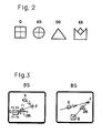
- the shape of the reference points can be selected as required. In the simplest case, these can be two balls. Versions such as rear sight and front sight, a square, a triangle, a circle or any other geometrical figure are also possible, which can be designed with crosshairs or without crosshairs. It is beneficial if there are two different geometric figures (e.g. a square and a triangle) on each line of sight.
- a pinhole can also be provided on the target device, which can be fixed in both positions.
- Two panels are also possible.
- the free diaphragm diameter is 20 mm
- the diaphragms are aligned concentrically with the home straight
- the outer diameters are larger than 10 cm
- 3 mm thick lead could be used as the diaphragm material.
- the panel is preferably designed to be folded away or simply removable.
- Figure 1 shows a patient's body, which is arranged within an X-ray C-arm on a couch, not shown.
- the X-ray C-arm contains an X-ray tube RR at the bottom and an image intensifier BV at the top, which are arranged colinearly.
- the X-ray C-arm can be pivoted about an axis which is approximately parallel to the longitudinal axis of the patient's body, so that the position of the X-ray tube RR and image intensifier BV shown in FIG. 1 can be reached.
- the shock wave source SQ is located on the patient's body PK, which is closed at the front with an elastic, flexible bellows.
- the shock wave source SQ generates shock waves, focuses them and directs them to the focus point F.
- the target device Z contains a carrier T by means of which it can be attached to the shock wave source SQ and, in this embodiment, four reference points R.
- the two left reference points R lie on the Straight line G1, which runs through the focus point F
- the two right reference points R lie on the straight line G2, which also runs through the focus point F.
- the procedure for X-ray location is now as follows:
- the shock wave source SQ is brought into the treatment position and the target device Z is clamped on.
- the couch with the patient's body PK is swung in and after the patient has been appropriately positioned, the shock wave source is coupled.
- the X-ray C-arm is provided free of charge.
- markings can be applied on which it is to be positioned.
- the beam direction is roughly predetermined by the target device, by the two left reference points R.
- the central beam is approximately aligned in this straight line (devices RR and BV drawn with a solid line).
- the two reference points R are now shown completely on top of each other or side by side on the screen.
- the position of the beam bundle relative to the shock wave source is defined from the position of the reference points in the image and the corresponding magnification of the image.
- the position and direction of the x-rays with respect to the reference system can thus be calculated from the known position of the shock wave source.
- the stone S is also visible on the screen.
- the patient's body PK is now moved so that the stone S with the focus F comes to cover. This can be checked through control recordings.
- the stone is now on a straight line that goes through the focus point F.
- the X-ray C-arm is tilted by a fixed angle (e.g. 30 °).
- the line of sight of the X-ray device roughly corresponds to the line defined by the two right reference points R.
- the picture shows the two reference points R and the stone again.
- the focus can be inferred from the position of the reference points R.
- the stone can be positioned on the focus F by moving the patient's body PK again. The success of the positioning can be checked by further recordings. Since the stone in the second projection lies on a known straight line that leads through F, the amount can be calculated from this recording around which the stone (the paitent) must be moved on this straight line.
- FIG. 2 shows four possible versions of reference points, namely a square Q, a circle KR, a triangle DR or a version with a rear sight and a grain KK.
- a crosshair made of X-ray-positive material is inserted in the square Q and in the circle KR. The positioning can also be carried out with figures (reference points) without crosshairs.
- Figure 3 shows two screens on the basis of which the location can be explained again.
- the left screen BS shows a picture from a first position, in which the X-ray tube and image intensifier are in the vicinity of the position shown in solid lines in FIG.
- a square Q and a triangle DR are provided as reference points R.
- the picture shows the two bodies, the square Q and the triangle DR.
- the focal point F can be calculated from their position, in particular from the mutual position of the focal points of the figures. This lies on a straight line that leads through the two focal points of the figures Q and DR.
- the stone S can also be seen in the picture. The treating doctor can now move the patient so that the stone S coincides with the focal point F.
- a possible evaluation can take place, for example, by providing a light pen with which the doctor taps the corner points of the square P1, P2, P3 and P4 and the corner points of the triangle P5, P6 and P7.
- a computer can form the centers of gravity from these seven coordinates, create a straight line through these points on the screen and generate the position of the focal point F.
- the table can also be moved automatically by the doctor after tapping the figures Q and DR also taps the stone S.
- a routine can then move the table to the fictional location of the focus point on the monitor.
- FIG. 3 shows on the right on the screen BS a picture which was taken from the subsequent second position of the X-ray C-arm (in the vicinity of the position shown in dashed lines in FIG. 1).
- the figures Q and DR as well as the stone S can be recognized again.
- the computer can in turn calculate the focal point F from the two figures Q and DR. Since the stone S is already on a defined straight line through the focus F, the displacement of the stone S into the focus point F can now also take place automatically.
- Another evaluation option, in which there is no need to enter points P1 to P7, is to call an image recognition routine, which recognizes the figures Q and DR, from the mutual position and the size of the figures, the imaging scale and the position of the focal point F can calculate.
Landscapes
- Health & Medical Sciences (AREA)
- Life Sciences & Earth Sciences (AREA)
- Medical Informatics (AREA)
- Engineering & Computer Science (AREA)
- Surgery (AREA)
- General Health & Medical Sciences (AREA)
- Veterinary Medicine (AREA)
- Biomedical Technology (AREA)
- Heart & Thoracic Surgery (AREA)
- Nuclear Medicine, Radiotherapy & Molecular Imaging (AREA)
- Molecular Biology (AREA)
- Animal Behavior & Ethology (AREA)
- Public Health (AREA)
- Orthopedic Medicine & Surgery (AREA)
- Vascular Medicine (AREA)
- Physics & Mathematics (AREA)
- Biophysics (AREA)
- High Energy & Nuclear Physics (AREA)
- Optics & Photonics (AREA)
- Pathology (AREA)
- Radiology & Medical Imaging (AREA)
- Apparatus For Radiation Diagnosis (AREA)
- Surgical Instruments (AREA)
- Radiation-Therapy Devices (AREA)
Abstract
Description
- Die Erfindung betrifft eine Zieleinrichtung zur Röntgenortung bei der extrakorporalen Behandlung vom Patienten mit fokussierten Stosswellen, insbesondere für einen Lithotripter.
- Die nicht invasive Steinzerkleinerung mit fokussierten Stosswellen erfordert eine genaue Ortung des Steines und eine genaue Positionierung des Patienten gegenüber dem Fokuspunkt, in dem sich die Stosswellen treffen.
- Angewandt werden bisher die Röntgenortung und die Ortung mit Ultraschallgeräten. Während die Ultraschallortung kontinuierlich durchführbar ist, scheidet ein permanentes "Röntgen-Filmen" wegen der Strahlenbelastung aus. Auf der anderen Seite lassen sich nicht alle Steinsorten vom Ultraschallgerät ausreichend abbilden.
- Es ist daher Aufgabe der Erfindung, ein Hilfsgerät anzubieten, mit dem eine Röntgenortung und Positionierung mit wenigen Röntgenbildern möglich ist.
- Diese Aufgabe wird von einer Zieleinrichtung mit den Merkmalen des Anspruchs 1 gelöst. Ausführungen der Erfindung sind Gegenstände von Unteransprüchen.
- Mit der erfindungsgemäßen Zieleinrichtung kann eine Positionierung mit Hilfe eines Röntgen-C-Bogens, der eine Röntgenröhre und ihr gegenüber einen Bildverstärker enthält, mit wenigen Bildern - das heißt mit geringer Strahlenbelastung - erreicht werden. Die Zieleinrichtung enthält auf einem röntgennegativen Material mindestens vier röntgenpositive Referenzpunkte, von denen mindestens zwei auf einer Geraden liegen, die durch den Stosswellenfokus geht, und mindestens zwei weitere Referenzpunkte, die auf einer anderen Geraden, die ebenfalls durch den Fokuspunkt verläuft, liegen. Mit Hilfe dieser vier Punkte lässt sich aus zwei Positionen des Röntgen-C-Bogens der Steinort finden und positionieren. Die Auswertung erfolgt nach dem "Kimme und Korn" Prinzip und kann auch von Hilfskräften am Monitor durchgeführt werden.
- Der Winkel zwischen den beiden Geraden, die in etwa den Visierlinien entsprechen, liegt bevorzugt zwischen 15 und 45°, insbesondere im Bereich von 30°. Der Abstand zweier Referenzpunkte auf einer Geraden liegt im Bereich zwischen 5 und 20 cm, insbesondere bei 10 cm.
- Für den Träger kommt ein röntgennegatives Material, wie zum Beispiel der Kunststoff Delrin, in Betracht. Der Träger soll möglichst nicht auf dem Bildschirm sichtbar werden. Die Massenverteilung senkrecht zur Durchstrahlungsrichtung sollte möglichst homogen sein. Eine Hohlkörperkonstruktion ist ebenso möglich. Die Aussenkontur sollte auf der dem Patienten zugewandten Seite körperfreundlich sein, das heißt keine scharfen Kanten aufweisen. Der Träger sollte möglichst einfach an der Stosswellenquelle befestigbar und wieder abnehmbar sein und so stabil, dass sich die Zieleinrichtung unter einer Last von ca. 30 kg nur soweit verformt, dass eine Verschiebung der Zielgeraden im mm-Bereich bleibt. Eine solche Belastung kann durch Anstossen des Zielgeräts an den Patientenkörper erfolgen.
- Die Referenzpunkte sollten aus möglichst röntgenpositivem Material bestehen, das sich kontrastreich auf dem Bildschirm darstellt. Als Material kommen alle Metalle mit hoher Ordnungszahl in betracht, wie zum Beispiel Stahl, Blei oder Lötzinn mit hohem Bleianteil.
- Die Form der Referenzpunkte ist beliebig wählbar. Im einfachsten Fall können dies zwei Kugeln sein. Möglich sind auch Ausführungen wie Kimme und Korn, ein Quadrat, ein Dreieck, ein Kreis oder irgend eine andere geometrische Figur, die mit Fadenkreuz oder ohne Fadenkreuz ausgeführt sein können. Günstig ist es, wenn sich auf einer Visierlinie jeweils zwei unterschiedliche geometrische Figuren (z.B. ein Quadrat und ein Dreieck) befinden.
- Zur nochmaligen Reduzierung der Strahlenbelastung beim Einrichten des Röntgen-C-Bogens kann auch eine Lochblende an der Zieleinrichtung vorgesehen sein, die in beiden Positionen fixierbar ist. Möglich sind ebenso zwei Blenden. In einer Ausführungsform beträgt der freie Blendendurchmesser 20 mm, die Blenden sind konzentrisch zu den Zielgeraden ausgerichtet, die Aussendurchmesser sind grösser 10 cm, als Blendenmaterial könnte 3 mm dickes Blei verwendet werden. Die Blende ist bevorzugt wegklappbar oder einfach abnehmbar ausgebildet.
- Die Erfindung wird anhand von drei Figuren näher erläutert.
- Es zeigen:
- Figur 1 eine erfindungsgemässe Zieleinrichtung,
- Figur 2 Ausführungen von Referenzpunkten und
- Figur 3 ein Auswerteverfahren anhand zweier Bildschirmdarstellungen.
- Figur 1 zeigt einen Patientenkörper, der innerhalb eines Röntgen-C-Bogens auf einer nicht gezeigten Liege angeordnet ist. Der Röntgen-C-Bogen enthält unten eine Röntgenröhre RR und oben einen Bildverstärker BV, die kolinear angeordnet sind. Der Röntgen-C-Bogen ist um eine Achse, die ungefähr parallel zur Längsachse des Patientenkörpers liegt, verschwenkbar, so dass die in Figur 1 gestrichelte Position von Röntgenröhre RR und Bildverstärker BV erreichbar ist. Am Patientenkörper PK befindet sich die Stosswellenquelle SQ, die hier an ihrer Vorderseite mit einem elastischen, flexiblem Balg abgeschlossen ist. Die Stosswellenquelle SQ erzeugt Stosswellen, fokussiert diese und leitet sie zum Fokuspunkt F. Die erfindungsgemässe Zieleinrichtung Z enthält einen Träger T, mittels dessen sie an der Stosswellenquelle SQ befestigt werden kann und in dieser Ausführung vier Referenzpunkte R. Die beiden linken Referenzpunkte R liegen auf der Geraden G1, die durch den Fokuspunkt F läuft, die beiden rechten Referenzpunkte R liegen auf der Geraden G2, die ebenfalls durch den Fokuspunkt F läuft.
- Zur Röntgenortung wird nun wie folgt vorgegangen:
Die Stosswellenquelle SQ wird etwa in die Behandlungsstellung gebracht und die Zieleinrichtung Z angeklemmt. Die Liege mit dem Patientenkörper PK wird eingeschwenkt und nach entsprechender Lagerung des Patienten wird die Stosswellenquelle angekoppelt. Der Röntgen-C-Bogen wird frei beigestellt. Auf dem Boden des Behandlungsraumes können zum Beispiel Markierungen aufgetragen sein, auf die er positioniert werden soll. Die Strahlrichtung ist durch die Zieleinrichtung, durch die beiden linken Referenzpunkte R, grob vorgegeben. In diese Gerade wird der Zentralstrahl ungefähr ausgerichtet (durchgezogen gezeichnete Geräte RR und BV). - Beim Aufnehmen eines Röntgenfotos sind nun die beiden Referenzpunkt R aufeinander oder nebeneinander vollständig auf dem Bildschirm dargestellt. Aus der Lage der Referenzpunkte im Bild und der entsprechenden Abbildungsvergrösserung ist die Lage des Strahlbüschels zur Stosswellenquelle definiert. Aus der bekannten Stellung der Stosswellenquelle ist somit die Lage und Richtung der Röntgenstrahlung bezüglich des Referenzsystems errechenbar. Auf dem Bildschirm ist auch der Stein S sichtbar. Der Patientenkörper PK wird nun so verschoben, dass der Stein S mit dem Fokus F zur Deckung kommt. Dies ist durch Kontrollaufnahmen nachprüfbar. Der Stein liegt jetzt auf einer Geraden, die durch den Fokuspunkt F geht.
- Im zweiten Schritt wird der Röntgen-C-Bogen um einen festen Winkel (z.B. 30°) gekippt. Die Visierlinie des Röntgengeräts entspricht in etwa der Linie, die von den beiden rechten Referenzpunkten R definiert wird. Bei einer Aufnahme zeigt das Bild nun wieder die beiden Referenzpunkte R und den Stein. Aus der Lage der Referenzpunkte R kann auf den Fokus geschlossen werden. Der Stein kann durch nochmaliges Verschieben des Patientenkörpers PK auf den Fokus F positioniert werden. Durch weitere Aufnahmen kann der Erfolg der Positionierung kontrolliert werden. Da der Stein in der zweiten Projektion auf einer bekannten Geraden, die durch F führt, liegt, kann aus dieser Aufnahme der Betrag errechnet werden, um den der Stein (der Paitent) auf dieser Geraden bewegt werden muß.
- Figur 2 zeigt vier mögliche Ausführungen von Referenzpunkten, nämlich ein Quadrat Q, einen Kreis KR, ein Dreieck DR oder eine Ausführung mit Kimme und Korn KK. In dem Quadrat Q und im Kreis KR ist jeweils ein Fadenkreuz aus röntenpositivem Material eingebracht. Durchführbar sind die Positionierungen aber auch mit Figuren (Referenzpunkten) ohne Fadenkreuz.
- Figur 3 zeigt zwei Bildschirme, anhand derer die Ortung nochmals erklärt werden kann. Der linke Bildschirm BS zeigt eine Aufnahme aus einer ersten Position, bei der Röntgenröhre und Bildverstärker in der Nähe der in Figur 1 durchgezogen gezeichneten Position stehen. Als Referenzpunkte R sind hier ein Quadrat Q und ein Dreieck DR vorgesehen. Das Bild zeigt die beiden Körper, das Quadrat Q und das Dreieck DR. Aus deren Lage, insbesondere aus der gegenseitigen Lage der Schwerpunkte der Figuren lässt sich der Brennpunkt F berechnen. Dieser liegt auf einer Geraden, die durch die beiden Schwerpunkte der Figuren Q und DR führt. Auf dem Bild ist auch der Stein S zu sehen. Der behandelnde Arzt kann nun den Patienten so verschieben, dass der Stein S mit dem Brennpunkt F zusammenfällt. Eine mögliche Auswertung kann zum Beispiel dadurch erfolgen, dass ein Light pen vorgesehen ist, mit dem der Arzt die Eckpunkte des Quadrates P1, P2, P3 und P4 sowie die Eckpunkte des Dreiecks P5, P6 und P7 antippt. Ein Rechner kann aus diesen sieben Koordinaten die Schwerpunkte bilden, eine Gerade durch diese Punkte im Bildschirm erzeugen und die Lage des Brennpunkts F generieren. Auch das Verfahren des Tisches kann automatisch erfolgen, indem der Arzt nach Antippen der Figuren Q und DR auch den Stein S antippt. Eine Routine kann den Tisch dann entsprechend zu dem fiktiven Ort des Fokuspunktes auf dem Monitor verfahren.
- Figur 3 zeigt rechts auf dem Bildschirm BS eine Aufnahme, die aus der anschliessenden zweiten Position des Röntgen-C-Bogens (in der Nähe der in Figur 1 gestrichelt gezeigten Position) aufgenommen wurde. Zu erkennen sind wieder die Figuren Q und DR, sowie der Stein S. Aus den beiden Figuren Q und DR kann der Rechner wiederum den Brennpunkt F berechnen. Da der Stein S bereits auf einer definierten Geraden durch den Fokus F liegt, kann auch jetzt die Verschiebung des Steins S in den Fokuspunkt F automatisch erfolgen.
- Eine andere Möglichkeit der Auswertung, bei der auf die Eingabe der Punkte P1 bis P7 verzichtet werden kann, ist das Aufrufen einer Bilderkennungsroutine, welche die Figuren Q und DR erkennt, aus der gegenseitigen Lage und der Grösse der Figuren den Abbildungsmaßstab und die Lage des Brennpunkts F berechnen kann.
Claims (5)
Applications Claiming Priority (2)
| Application Number | Priority Date | Filing Date | Title |
|---|---|---|---|
| DE3919083A DE3919083C1 (de) | 1989-06-10 | 1989-06-10 | |
| DE3919083 | 1989-06-10 |
Publications (2)
| Publication Number | Publication Date |
|---|---|
| EP0402584A1 true EP0402584A1 (de) | 1990-12-19 |
| EP0402584B1 EP0402584B1 (de) | 1994-11-02 |
Family
ID=6382553
Family Applications (1)
| Application Number | Title | Priority Date | Filing Date |
|---|---|---|---|
| EP90106214A Expired - Lifetime EP0402584B1 (de) | 1989-06-10 | 1990-03-31 | Zieleinrichtung für Lithotripter |
Country Status (5)
| Country | Link |
|---|---|
| US (1) | US5070861A (de) |
| EP (1) | EP0402584B1 (de) |
| JP (1) | JPH0691887B2 (de) |
| DE (1) | DE3919083C1 (de) |
| ES (1) | ES2066030T3 (de) |
Cited By (4)
| Publication number | Priority date | Publication date | Assignee | Title |
|---|---|---|---|---|
| DE4135328A1 (de) * | 1991-10-25 | 1993-04-29 | Wolf Gmbh Richard | Extrakorporales therapiegeraet |
| FR2686258A1 (fr) * | 1992-01-21 | 1993-07-23 | Edap Int | Procede de visee d'une cible anatomique en vue de son traitement par ondes elastiques focalisees et appareil faisant application de ce procede au traitement de la prostate par hyperthermie. |
| DE4300740C1 (de) * | 1993-01-14 | 1994-03-17 | Wolf Gmbh Richard | Extrakorpolares Therapiegerät |
| DE102005031118A1 (de) * | 2005-07-04 | 2007-01-11 | Siemens Ag | Verfahren und Einrichtung zur Ausrichtung eines Fokuspunktes einer Ultraschallstoßwelle auf ein Ziel in einem Patienten |
Families Citing this family (41)
| Publication number | Priority date | Publication date | Assignee | Title |
|---|---|---|---|---|
| DE3835318C1 (de) * | 1988-10-17 | 1990-06-28 | Storz Medical Ag, Kreuzlingen, Ch | |
| FR2665545B1 (fr) * | 1990-08-06 | 1993-09-24 | Technomed Int Sa | Procede et appareil de determination de la position d'une cible par rapport a un repere de reference de coordonnees connues sans connaitre a priori la position d'une source de rayonnement. |
| EP0502069A1 (de) * | 1989-11-24 | 1992-09-09 | Technomed International | Verfahren und vorrichtung zur feststellung der position eines ziels in bezug auf bekannte koordinaten |
| JPH0745206Y2 (ja) * | 1989-12-30 | 1995-10-18 | 株式会社島津製作所 | 結石破砕治療システム |
| DE4003350C1 (en) * | 1990-02-05 | 1991-04-25 | Dornier Medizintechnik Gmbh, 8000 Muenchen, De | C-bow X=ray appts. setter for lithotriptor - uses metal sphere on support as reference element for position of therapy focus |
| DE4033439C1 (de) * | 1990-10-20 | 1991-11-28 | Dornier Medizintechnik Gmbh, 8000 Muenchen, De | |
| DE4100653C1 (en) * | 1991-01-11 | 1992-05-14 | Dornier Medizintechnik Gmbh, 8000 Muenchen, De | Targetting arrangement for locating X=ray - has sight on impact wave source providing at least four reference points in single plane |
| DE4101469C1 (en) * | 1991-01-19 | 1992-06-17 | Dornier Medizintechnik Gmbh, 8000 Muenchen, De | Lithotripsy equipment spatially locating and positioning calculi - has optical collimating lens between optical cross hair sights and X=ray absorbing cross hair, central point being in ultrasonic image plane |
| DE4106370C1 (en) * | 1991-02-28 | 1992-06-17 | Dornier Medizintechnik Gmbh, 8000 Muenchen, De | C-arch X=ray appts. adjuster for lithotripsy - has deflector unit directing light beams projected onto focus point of X=ray tube to point marked on projection screen |
| DE4109558A1 (de) * | 1991-03-24 | 1992-10-01 | Storz Medical Ag | Vorrichtung zur erzeugung von fokussierten akustischen druck- oder stosswellen fuer therapeutische anwenduungen mit einer roentgen-ortungseinrichtung |
| FR2680578B1 (fr) * | 1991-08-21 | 1994-04-15 | Technomed International | Procede et dispositif pour determiner la position exacte d'une cible (c) par alignement de moyens de reperage avec la cible et utilisation dans le cadre d'un appareil de traitement de ladite cible, de preference a ondes de pression. |
| DE4143540C2 (de) * | 1991-10-24 | 1996-08-08 | Siemens Ag | Therapieeinrichtung zur Behandlung eines Patienten mit fokussierten akustischen Wellen |
| US5306271A (en) * | 1992-03-09 | 1994-04-26 | Izi Corporation | Radiation therapy skin markers |
| DE4211274C1 (en) * | 1992-04-03 | 1993-04-15 | Siemens Ag, 8000 Muenchen, De | Medical treatment unit e.g. for bone fractures - produces marking on monitor to indicate different positions of radiation beam in region to be treated |
| US5372132A (en) * | 1992-07-09 | 1994-12-13 | Biomagnetic Technologies, Inc. | Sensor positioning aid and method |
| DE4306460C2 (de) * | 1993-03-02 | 1995-04-20 | Siemens Ag | Therapieeinrichtung zur Behandlung mit fokussierten akustischen Wellen |
| DE4306459C1 (de) * | 1993-03-02 | 1994-04-28 | Siemens Ag | Therapieeinrichtung zur Behandlung mit fokussierten akustischen Wellen |
| US5595178A (en) * | 1994-10-02 | 1997-01-21 | Hmt High Medical Technologies Gmbh | System, method and apparatus for treatment of degenerative bone |
| US7189209B1 (en) | 1996-03-29 | 2007-03-13 | Sanuwave, Inc. | Method for using acoustic shock waves in the treatment of a diabetic foot ulcer or a pressure sore |
| US6390995B1 (en) | 1997-02-12 | 2002-05-21 | Healthtronics Surgical Services, Inc. | Method for using acoustic shock waves in the treatment of medical conditions |
| US5967982A (en) * | 1997-12-09 | 1999-10-19 | The Cleveland Clinic Foundation | Non-invasive spine and bone registration for frameless stereotaxy |
| US6036696A (en) * | 1997-12-19 | 2000-03-14 | Stryker Technologies Corporation | Guide-pin placement device and method of use |
| DE19822793C2 (de) * | 1998-05-20 | 2000-05-31 | Siemens Ag | Vorrichtung zur Kennzeichnung der Lage des Fokus einer Stoßwellenquelle |
| FR2799109A1 (fr) * | 1999-10-01 | 2001-04-06 | Internova Int Innovation | Procede de reperage par rayons x d'une anomalie anatomique interne |
| US6656189B1 (en) | 2000-05-25 | 2003-12-02 | Synthes (Usa) | Radiolucent aiming guide |
| DE10062749C1 (de) * | 2000-12-15 | 2002-04-04 | Dornier Medtech Holding Int Gmbh | Koppelbalg zur Stoßwellentherapie |
| DE10158519B4 (de) * | 2001-11-29 | 2005-01-13 | Dornier Medtech Holding International Gmbh | Stoß- und Druckwellen-Therapiegerät |
| DE10234144A1 (de) * | 2002-07-26 | 2004-02-05 | Dornier Medtech Gmbh | Lithotripter |
| EP1493389A1 (de) * | 2003-07-01 | 2005-01-05 | Siemens Aktiengesellschaft | Verfahren und Einrichtung zum Erzeugen eines Röntgenbildes aus der Fokusregion eines Lithotripters |
| DE102004006021A1 (de) * | 2004-02-06 | 2005-09-01 | Dornier Medtech Systems Gmbh | Verfahren und Vorrichtung zum Positionieren des Fokuspunkts einer Wellenquelle zu einem Zielobjekt außerhalb des Isozentrums |
| DE102004010005B4 (de) * | 2004-03-01 | 2009-07-23 | Siemens Ag | Anlage zur bildgestützten Stoßwellenbehandllung |
| DE102004038848B4 (de) * | 2004-08-10 | 2009-10-08 | Siemens Ag | Stoßwellenkopf mit einer Einrichtung zur Kontrolle der Lage seines Fokus |
| US7481815B2 (en) | 2004-09-23 | 2009-01-27 | Synthes (U.S.A.) | Coplanar X-ray guided aiming arm for locking of intramedullary nails |
| DE602005019367D1 (de) | 2004-12-15 | 2010-04-01 | Dornier Medtech Systems Gmbh | Verbesserte Zelltherapie und Gewebsregeneration mittels Stosswellen bei Patienten mit kardiovaskulären and neurologischen Krankheiten |
| AU2006227622A1 (en) * | 2005-03-17 | 2006-09-28 | Smith & Nephew, Inc. | Medical securing member placement system |
| DE102005037043C5 (de) | 2005-08-05 | 2017-12-14 | Dornier Medtech Systems Gmbh | Stoßwellentherapiegerät mit Bildgewinnung |
| US9192398B2 (en) * | 2005-09-19 | 2015-11-24 | DePuy Synthes Products, Inc. | Orthopedic implant insertion handle and aiming guide |
| DE102006002273A1 (de) * | 2006-01-17 | 2007-07-26 | Dornier Medtech Systems Gmbh | Behandlungseinrichtung |
| US8979776B2 (en) * | 2008-05-02 | 2015-03-17 | Daniel Gelbart | Lithotripsy system with automatic 3D tracking |
| CN102068294B (zh) * | 2011-01-27 | 2012-06-13 | 华中科技大学 | 冲击波碎石机辅助定位系统 |
| DE102011082680B4 (de) * | 2011-09-14 | 2019-12-24 | Siemens Healthcare Gmbh | Anlage |
Citations (4)
| Publication number | Priority date | Publication date | Assignee | Title |
|---|---|---|---|---|
| US3711712A (en) * | 1970-12-28 | 1973-01-16 | Laren R Mc | Method and device for locating a foreign body in human eye |
| EP0018166A1 (de) * | 1979-04-13 | 1980-10-29 | Pfizer Inc. | Apparat zur Verwendung in der stereotaktischen Chirurgie |
| EP0257429A1 (de) * | 1986-08-22 | 1988-03-02 | Siemens Aktiengesellschaft | Lithotripsie-Arbeitsplatz |
| US4764944A (en) * | 1986-06-18 | 1988-08-16 | University Of Florida | Methods for positioning an internal portion of a body relative to an extracorporeal referent |
Family Cites Families (4)
| Publication number | Priority date | Publication date | Assignee | Title |
|---|---|---|---|---|
| US3609358A (en) * | 1970-04-09 | 1971-09-28 | Benedict J Salesi | Hand held x-ray guide |
| US3991310A (en) * | 1970-08-03 | 1976-11-09 | Morrison Richard A | Biplane radiographic localization of target center for radiotherapy |
| DE3426398C1 (de) * | 1984-07-18 | 1987-11-12 | Dornier System Gmbh, 7990 Friedrichshafen | Vorrichtung zum räumlichen Orten und Positionieren von Konkrementen |
| US4930509A (en) * | 1989-01-23 | 1990-06-05 | Northgate Research, Inc. | X-ray aiming fixture |
-
1989
- 1989-06-10 DE DE3919083A patent/DE3919083C1/de not_active Expired - Fee Related
-
1990
- 1990-03-31 EP EP90106214A patent/EP0402584B1/de not_active Expired - Lifetime
- 1990-03-31 ES ES90106214T patent/ES2066030T3/es not_active Expired - Lifetime
- 1990-05-14 JP JP2123990A patent/JPH0691887B2/ja not_active Expired - Lifetime
- 1990-06-11 US US07/535,719 patent/US5070861A/en not_active Expired - Fee Related
Patent Citations (4)
| Publication number | Priority date | Publication date | Assignee | Title |
|---|---|---|---|---|
| US3711712A (en) * | 1970-12-28 | 1973-01-16 | Laren R Mc | Method and device for locating a foreign body in human eye |
| EP0018166A1 (de) * | 1979-04-13 | 1980-10-29 | Pfizer Inc. | Apparat zur Verwendung in der stereotaktischen Chirurgie |
| US4764944A (en) * | 1986-06-18 | 1988-08-16 | University Of Florida | Methods for positioning an internal portion of a body relative to an extracorporeal referent |
| EP0257429A1 (de) * | 1986-08-22 | 1988-03-02 | Siemens Aktiengesellschaft | Lithotripsie-Arbeitsplatz |
Cited By (6)
| Publication number | Priority date | Publication date | Assignee | Title |
|---|---|---|---|---|
| DE4135328A1 (de) * | 1991-10-25 | 1993-04-29 | Wolf Gmbh Richard | Extrakorporales therapiegeraet |
| FR2686258A1 (fr) * | 1992-01-21 | 1993-07-23 | Edap Int | Procede de visee d'une cible anatomique en vue de son traitement par ondes elastiques focalisees et appareil faisant application de ce procede au traitement de la prostate par hyperthermie. |
| EP0552995A1 (de) * | 1992-01-21 | 1993-07-28 | Edap International | Verfahren zum Anvisieren eines anatomischen Ziels zu seiner Behandlung mit fokussierten elastischen Wellen und Verwendung dieses Verfahrens zur Hyperthermiebehandlung der Prostata |
| DE4300740C1 (de) * | 1993-01-14 | 1994-03-17 | Wolf Gmbh Richard | Extrakorpolares Therapiegerät |
| EP0606548A1 (de) * | 1993-01-14 | 1994-07-20 | Richard Wolf GmbH | Extrakorporales Therapiegerät |
| DE102005031118A1 (de) * | 2005-07-04 | 2007-01-11 | Siemens Ag | Verfahren und Einrichtung zur Ausrichtung eines Fokuspunktes einer Ultraschallstoßwelle auf ein Ziel in einem Patienten |
Also Published As
| Publication number | Publication date |
|---|---|
| DE3919083C1 (de) | 1990-06-21 |
| EP0402584B1 (de) | 1994-11-02 |
| US5070861A (en) | 1991-12-10 |
| JPH03103251A (ja) | 1991-04-30 |
| ES2066030T3 (es) | 1995-03-01 |
| JPH0691887B2 (ja) | 1994-11-16 |
Similar Documents
| Publication | Publication Date | Title |
|---|---|---|
| EP0402584B1 (de) | Zieleinrichtung für Lithotripter | |
| DE19917867B4 (de) | Verfahren und Vorrichtung zur Bildunterstützung bei der Behandlung von Behandlungszielen mit Integration von Röntgenerfassung und Navigationssystem | |
| EP2082687B1 (de) | Überlagerte Darstellung von Aufnahmen | |
| DE3901495C2 (de) | ||
| EP0360322B1 (de) | Verfahren zum Positionieren eines auf einer Tischplatte eines Lagerungstisches befindlichen Patienten und Gerät zum Durchführen des Verfahrens | |
| EP0257429B1 (de) | Lithotripsie-Arbeitsplatz | |
| WO2011144412A1 (de) | Bestimmung und überprüfung der koordinatentransformation zwischen einem röntgensystem und einem operationsnavigationssystem | |
| DE102005062582B4 (de) | Abbilduingssystem und Verfahren zur Anfertigung von Röntgen- und optischen Bildern | |
| DE4033439C1 (de) | ||
| EP0715831A1 (de) | Lithotripsiekombination mit einer Therapieeinheit | |
| EP0273256A1 (de) | Vorrichtung zum berührungslosen Zertrümmern von Konkrementen | |
| DE4306460C2 (de) | Therapieeinrichtung zur Behandlung mit fokussierten akustischen Wellen | |
| DE4135328C2 (de) | Extrakorporales Therapiegerät | |
| DE4003350C1 (en) | C-bow X=ray appts. setter for lithotriptor - uses metal sphere on support as reference element for position of therapy focus | |
| EP0400168B1 (de) | Medizintechnische Anlage zur Positionierung eines Therapiegerätes | |
| DE4306459C1 (de) | Therapieeinrichtung zur Behandlung mit fokussierten akustischen Wellen | |
| DE8528785U1 (de) | Lithotripsie-Arbeitsplatz | |
| DE102007029199B4 (de) | Verfahren zum Ausrichten eines Zielführungssystems für eine Punktion und Röntgenangiographiesystem nebst Verfahren zum technischen Unterstützen der Zielführung | |
| DE102019214302A1 (de) | Verfahren zum Registrieren eines Röntgenbilddatensatzes mit einem Navigationssystem, Computerprogrammprodukt und System | |
| DE102013209769A1 (de) | Röntgenbildgebungsgerät zum Stitching und zugehöriges Verfahren | |
| DE102011089178B4 (de) | Verfahren zur Aufnahme eines Projektionsbildes und Bildgebungseinrichtung | |
| EP0532732B1 (de) | Vorrichtung zur erzeugung von fokussierten akustischen druck- oder stosswellen für therapeutische anwendungen mit einer röntgen-ortungseinrichtung | |
| DE4325212A1 (de) | Medizinisches Gerät | |
| DE10346966B4 (de) | Kompressionsplatte für ein Mammographiegerät und Röntgendiagnostikgerät | |
| DE20109313U1 (de) | Robotergestützte Röntgensysteme zur Bildgebung und Lokalisation in der Strahlentherapie |
Legal Events
| Date | Code | Title | Description |
|---|---|---|---|
| PUAI | Public reference made under article 153(3) epc to a published international application that has entered the european phase |
Free format text: ORIGINAL CODE: 0009012 |
|
| AK | Designated contracting states |
Kind code of ref document: A1 Designated state(s): CH ES FR GB IT LI |
|
| 17P | Request for examination filed |
Effective date: 19910130 |
|
| 17Q | First examination report despatched |
Effective date: 19930601 |
|
| GRAA | (expected) grant |
Free format text: ORIGINAL CODE: 0009210 |
|
| AK | Designated contracting states |
Kind code of ref document: B1 Designated state(s): CH ES FR GB IT LI |
|
| GBT | Gb: translation of ep patent filed (gb section 77(6)(a)/1977) |
Effective date: 19941201 |
|
| ITF | It: translation for a ep patent filed | ||
| REG | Reference to a national code |
Ref country code: ES Ref legal event code: FG2A Ref document number: 2066030 Country of ref document: ES Kind code of ref document: T3 |
|
| ET | Fr: translation filed | ||
| PLBE | No opposition filed within time limit |
Free format text: ORIGINAL CODE: 0009261 |
|
| STAA | Information on the status of an ep patent application or granted ep patent |
Free format text: STATUS: NO OPPOSITION FILED WITHIN TIME LIMIT |
|
| 26N | No opposition filed | ||
| REG | Reference to a national code |
Ref country code: CH Ref legal event code: PL |
|
| GBPC | Gb: european patent ceased through non-payment of renewal fee |
Effective date: 20010331 |
|
| REG | Reference to a national code |
Ref country code: CH Ref legal event code: AEN Free format text: DAS PATENT IST AUFGRUND DES WEITERBEHANDLUNGSANTRAGS VOM 31.10.2001 REAKTIVIERT WORDEN. |
|
| REG | Reference to a national code |
Ref country code: FR Ref legal event code: ST |
|
| REG | Reference to a national code |
Ref country code: FR Ref legal event code: FC |
|
| REG | Reference to a national code |
Ref country code: GB Ref legal event code: 728V |
|
| REG | Reference to a national code |
Ref country code: GB Ref legal event code: 728Y |
|
| PGFP | Annual fee paid to national office [announced via postgrant information from national office to epo] |
Ref country code: GB Payment date: 20050225 Year of fee payment: 16 |
|
| PGFP | Annual fee paid to national office [announced via postgrant information from national office to epo] |
Ref country code: ES Payment date: 20050307 Year of fee payment: 16 |
|
| PGFP | Annual fee paid to national office [announced via postgrant information from national office to epo] |
Ref country code: FR Payment date: 20050316 Year of fee payment: 16 |
|
| PGFP | Annual fee paid to national office [announced via postgrant information from national office to epo] |
Ref country code: CH Payment date: 20050321 Year of fee payment: 16 |
|
| PG25 | Lapsed in a contracting state [announced via postgrant information from national office to epo] |
Ref country code: LI Free format text: LAPSE BECAUSE OF NON-PAYMENT OF DUE FEES Effective date: 20060331 Ref country code: GB Free format text: LAPSE BECAUSE OF NON-PAYMENT OF DUE FEES Effective date: 20060331 Ref country code: CH Free format text: LAPSE BECAUSE OF NON-PAYMENT OF DUE FEES Effective date: 20060331 |
|
| PGFP | Annual fee paid to national office [announced via postgrant information from national office to epo] |
Ref country code: IT Payment date: 20060331 Year of fee payment: 17 |
|
| PG25 | Lapsed in a contracting state [announced via postgrant information from national office to epo] |
Ref country code: ES Free format text: LAPSE BECAUSE OF NON-PAYMENT OF DUE FEES Effective date: 20060401 |
|
| REG | Reference to a national code |
Ref country code: CH Ref legal event code: PL |
|
| GBPC | Gb: european patent ceased through non-payment of renewal fee |
Effective date: 20060331 |
|
| REG | Reference to a national code |
Ref country code: FR Ref legal event code: ST Effective date: 20061130 |
|
| REG | Reference to a national code |
Ref country code: ES Ref legal event code: FD2A Effective date: 20060401 |
|
| PG25 | Lapsed in a contracting state [announced via postgrant information from national office to epo] |
Ref country code: FR Free format text: LAPSE BECAUSE OF NON-PAYMENT OF DUE FEES Effective date: 20060331 |
|
| PG25 | Lapsed in a contracting state [announced via postgrant information from national office to epo] |
Ref country code: IT Free format text: LAPSE BECAUSE OF NON-PAYMENT OF DUE FEES Effective date: 20070331 |