EP0402489B1 - Anordnung zur Befestigung eines Gurtbandes an einer Welle eines Sicherheitsgurtaufrollers - Google Patents
Anordnung zur Befestigung eines Gurtbandes an einer Welle eines Sicherheitsgurtaufrollers Download PDFInfo
- Publication number
- EP0402489B1 EP0402489B1 EP89110507A EP89110507A EP0402489B1 EP 0402489 B1 EP0402489 B1 EP 0402489B1 EP 89110507 A EP89110507 A EP 89110507A EP 89110507 A EP89110507 A EP 89110507A EP 0402489 B1 EP0402489 B1 EP 0402489B1
- Authority
- EP
- European Patent Office
- Prior art keywords
- shaft
- web
- webbing
- belt
- belt webbing
- Prior art date
- Legal status (The legal status is an assumption and is not a legal conclusion. Google has not performed a legal analysis and makes no representation as to the accuracy of the status listed.)
- Expired - Lifetime
Links
Images
Classifications
-
- B—PERFORMING OPERATIONS; TRANSPORTING
- B60—VEHICLES IN GENERAL
- B60R—VEHICLES, VEHICLE FITTINGS, OR VEHICLE PARTS, NOT OTHERWISE PROVIDED FOR
- B60R22/00—Safety belts or body harnesses in vehicles
- B60R22/34—Belt retractors, e.g. reels
-
- B—PERFORMING OPERATIONS; TRANSPORTING
- B60—VEHICLES IN GENERAL
- B60R—VEHICLES, VEHICLE FITTINGS, OR VEHICLE PARTS, NOT OTHERWISE PROVIDED FOR
- B60R22/00—Safety belts or body harnesses in vehicles
- B60R22/34—Belt retractors, e.g. reels
- B60R2022/3427—Seat belt connection on reels
Definitions
- the invention relates to an arrangement for fastening a webbing to a shaft of a seat belt retractor, which has an axial slot through which the webbing is passed, the webbing being wrapped around a web defined by the axial slot before it is wound onto the core of the shaft becomes.
- the invention has for its object to provide an arrangement for fastening a belt to a shaft of a seat belt retractor, in which both a seam of the belt and additional parts such as clips, clamps or the like are unnecessary, and the assembly is therefore simplified.
- the core of the shaft is formed by two webs delimited by the axial slot and the belt strap is inserted at its end into a groove provided on the outer circumference of one web of the shaft and with at least two turns around this web.
- the end of the webbing is held in the groove of one web with only moderate force. Since the webbing is then wrapped around the web with at least two turns, a wrap friction additionally occurs, by means of which the holding force with which the webbing end is held in the groove is increased according to an exponential law, into which the wrap angle is included as an exponent. With just two turns, a holding force is already achieved, which meets the usual test conditions.
- the web, around which the webbing is laid with at least two turns has an outer diameter which is reduced by so much compared to the other web of the shaft that the outer diameter of the web surrounded by a plurality of webbing layers is approximately equal to the outer diameter of the other Is web.
- the groove into which the belt end is inserted is parallel to the axial slot. In this way, almost two complete turns can be realized by twisting the webbing around the web in question.
- the end of the webbing is pressed into the groove, which is facilitated by a slightly V-shaped design of the groove in cross section.
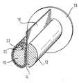
- FIG. 1 shows a schematic representation, partly in section, of the shaft of a seat belt retractor with the strap end attached to it.
- the two webs 10, 12 of the shaft of a belt retractor are separated from one another by a continuous axial slot 14.
- the webbing 18 runs through the axial slot 14 and is wrapped around the web 10 with two turns.
- the end of the webbing designated 20 is inserted into an axial groove 22 of the web 10.
- the axial groove 20 runs parallel to the axial slot 14 and has a slightly V-shaped cross section, so that the end of the webbing can be pressed into the groove.
- the outer diameter of the web 10 is slightly smaller than that of the web 12 in order to take into account the two webbing layers, so that the web 10 with the two webbing layers and the web 12 have approximately the same outer diameter.
Landscapes
- Engineering & Computer Science (AREA)
- Mechanical Engineering (AREA)
- Automotive Seat Belt Assembly (AREA)
- Storage Of Web-Like Or Filamentary Materials (AREA)
- Replacement Of Web Rolls (AREA)
- Emergency Lowering Means (AREA)
- Automobile Manufacture Line, Endless Track Vehicle, Trailer (AREA)
Description
- Die Erfindung betrifft eine Anordnung zur Befestigung eines Gurtbandes an einer Welle eines Sicherheitsgurtaufrollers, die einen axialen Schlitz aufweist, durch den das Gurtband hindurchgeführt ist, wobei das Gurtband um einen durch den axialen Schlitz abgegrenzten Steg herumgelegt ist, bevor es auf den Kern der Welle aufgewickelt wird.
- Eine Anordnung dieser Gattung ist aus der FR-A 2 331 942 bekannt. Das dort beschriebene Befestigungselement für ein Gurtband weist eine Welle auf, die durch zwei parallel verlaufende, schmale Schlitze in drei Teile geteilt ist. Das Gurtband wird zunächst durch einen ersten Schlitz geführt und dann um den von dem zweiten Schlitz abgegrenzten äußeren Teil der Welle gelegt. Anschließend wird das Gurtband durch den zweiten Schlitz geführt, wonach es in entgegengesetzter Richtung nochmals durch den ersten Schlitz geführt wird. Bei einer solchen Anordnung ist keine Naht erforderlich, um das Gurtband mit ausreichender Sicherheit an der Welle des Gurtaufrollers zu befestigen. Auch wird kein zusätzliches Befestigungselement benötigt, um das Ende des Gurtbandes an der Welle festzulegen. Diese Anordnung besitzt jedoch den Nachteil, daß die Montage des Gurtbandes umständlich ist.
- Der Erfindung liegt die Aufgabe zugrunde, eine Anordnung zur Befestigung eines Gurtbandes an einer Welle eines Sicherheitsgurtaufrollers zu schaffen, bei der sich sowohl eine Naht des Gurtbandes als auch zusätzliche Teile wie Klammern, Klemmstücke oder dergleichen erübrigen, und die Montage daher vereinfacht wird.
- Diese Aufgabe wird bei einer Anordnung der eingangs angegebenen Art erfindungsgemäß dadurch gelöst, daß der Kern der Welle durch zwei von dem axialen Schlitz begrenzte Stege gebildet wird und das Gurtband an seinem Ende in eine am Außenumfang des einen Steges der Welle angebrachte Nut eingesteckt und mit wenigstens zwei Windungen um diesen Steg herumgelegt ist. Bei der erfindungsgemäßen Anordnung wird das Gurtbandende in der Nut des einen Steges mit nur mäßiger Kraft gehalten. Da das Gurtband anschließend mit wenigstens zwei Windungen um den Steg herumgelegt wird, tritt zusätzlich eine Umschlingungsreibung auf, durch die die Haltekraft, mit der das Gurtbandende in der Nut gehalten wird, nach einer exponentiellen Gesetzmäßigkeit verstärkt wird, in die der Umschlingungswinkel als Exponent eingeht. Mit lediglich zwei Windungen wird bereits eine Haltekraft erzielt, die üblichen Prüfbedingungen genügt. Ein Abwickeln der Windungen von dem Steg ist nicht möglich, da das Gurtband zur Vervollständigung der zwei oder mehr Windungen auf dem einen Steg wieder durch den axialen Schlitz zwischen beiden Stegen hindurchgeführt werden muß und infolgedessen das Ende der den Steg umgebenden Windungen in dem axialen Schlitz gehalten ist.
- Um einen gleichmäßigen Wicklungsaufbau zu gewährleisten, weist der Steg, um den das Gurtband mit wenigstens zwei Windungen herumgelegt ist, einen gegenüber dem anderen Steg der Welle um soviel verminderten Außendurchmesser auf, daß der Außendurchmesser des von mehreren Gurtbandlagen umgebenen Steges annähernd gleich dem Außendurchmesser des anderen Steges ist.
- Von Vorteil ist weiterhin, wenn gemäß einer bevorzugten Ausführungsform die Nut, in welche das Gurtbandende eingesteckt ist, parallel zu dem axialen Schlitz verläuft. Auf diese Weise lassen sich durch zweimaliges Herumlegen des Gurtbandes um den betreffenden Steg nahezu zwei vollständige Windungen realisieren.
- Ferner ist bei der bevorzugten Auführungsform das Gurtbandende in die Nut eingepreßt, was durch eine im Querschnitt leicht V-förmige Gestaltung der Nut erleichtert wird.
- Eine bevorzugte Ausführungsform der Erfindung wird nun unter Bezugnahme auf die Zeichnung näher beschrieben. Die einzige Figur der Zeichnung zeigt eine teilweise im Schnitt wiedergegebene schematische Darstellung der Welle eines Sicherheitsgurtaufrollers mit dem daran befestigten Gurtbandende.
- Die zwei Stege 10, 12 der Welle eines Gurtaufrollers sind durch einen durchgehenden axialen Schlitz 14 voneinander getrennt. An den beiden Enden der Welle befindet sich jeweils ein Flansch 16. Das Gurtband 18 verläuft durch den axialen Schlitz 14 und ist mit zwei Windungen um den Steg 10 herumgelegt. Das mit 20 bezeichnete Ende des Gurtbandes ist in eine axiale Nut 22 des Steges 10 eingesteckt. Die axiale Nut 20 verläuft parallel zu dem axialen Schlitz 14 und ist im Querschnitt leicht V-förmig gestaltet, so daS das Gurtbandende in die Nut eingepreßt werden kann. Der Außendurchmesser des Steges 10 ist etwas kleiner als der des Steges 12, um die beiden Gurtbandlagen zu berücksichtigen, so daß der Steg 10 mit den beiden Gurtbandlagen und der Steg 12 annähernd denselben Außendurchmesser aufweisen. Wie aus der Zeichnung ohne weiteres ersichtlich ist, werden zur Befestigung des Gurtbandes an der Welle keine besonderen Teile benötigt, wodurch nicht nur der Bauteileaufwand vermindert, sondern auch die Montage erleichtert wird.
Claims (4)
- Anordnung zur Befestigung eines Gurtbandes (18) an einer Welle eines Sicherheitsgurtaufrollers, die einen axialen Schlitz (14) aufweist, durch den das Gurtband hindurchgeführt ist, wobei das Gurtband (18) um einen durch den axialen Schlitz (14) abgegrenzten Steg (10) herumgelegt ist, bevor es auf den Kern der Welle aufgewickelt wird, dadurch gekennzeichnet, daß der Kern der Welle durch zwei von dem Schlitz (14) begrenzte Stege (10, 12) gebildet ist und das Gurtband an seinem Ende (22) in eine am Außenumfang des einen Steges (10) der Welle angebrachte Nut (20) eingesteckt und mit wenigstens zwei Windungen um diesen Steg (10) herumgelegt ist.
- Anordnung nach Anspruch 1, dadurch gekennzeichnet, daß der Steg (10), um den das Gurtband mit wenigstens zwei Windungen herumgelegt ist, einen gegenüber dem anderen Steg (12) der Welle um soviel verminderten Außendurchmesser aufweist, daß der Außendurchmesser des von mehreren Gurtbandlagen umgebenen Steges (10) annähernd gleich dem Außendurchmesser des anderen Steges (12) ist.
- Anordnung nach Anspruch 1 oder 2, dadurch gekennzeichnet, daß die Nut (20) parallel zu dem axialen Schlitz verläuft.
- Anordnung nach einem der vorstehenden Ansprüche, dadurch gekennzeichnet, daß das Gurtbandende in die im Querschnitt annähernd V-förmige Nut (20) eingepreßt ist.
Priority Applications (6)
| Application Number | Priority Date | Filing Date | Title |
|---|---|---|---|
| DE8989110507T DE58903978D1 (de) | 1989-06-10 | 1989-06-10 | Anordnung zur befestigung eines gurtbandes an einer welle eines sicherheitsgurtaufrollers. |
| AT89110507T ATE87558T1 (de) | 1989-06-10 | 1989-06-10 | Anordnung zur befestigung eines gurtbandes an einer welle eines sicherheitsgurtaufrollers. |
| ES198989110507T ES2018755T3 (es) | 1989-06-10 | 1989-06-10 | Dispositivo para la fijacion de un cinturon en un eje de un retractor de cinturon de seguridad. |
| EP89110507A EP0402489B1 (de) | 1989-06-10 | 1989-06-10 | Anordnung zur Befestigung eines Gurtbandes an einer Welle eines Sicherheitsgurtaufrollers |
| JP2121048A JPH0733213B2 (ja) | 1989-06-10 | 1990-05-10 | 織布状安全ベルトを安全ベルト引込み装置の軸に固定するための構造 |
| US07/522,994 US5065953A (en) | 1989-06-10 | 1990-05-14 | Safety belt retractor |
Applications Claiming Priority (1)
| Application Number | Priority Date | Filing Date | Title |
|---|---|---|---|
| EP89110507A EP0402489B1 (de) | 1989-06-10 | 1989-06-10 | Anordnung zur Befestigung eines Gurtbandes an einer Welle eines Sicherheitsgurtaufrollers |
Publications (2)
| Publication Number | Publication Date |
|---|---|
| EP0402489A1 EP0402489A1 (de) | 1990-12-19 |
| EP0402489B1 true EP0402489B1 (de) | 1993-03-31 |
Family
ID=8201485
Family Applications (1)
| Application Number | Title | Priority Date | Filing Date |
|---|---|---|---|
| EP89110507A Expired - Lifetime EP0402489B1 (de) | 1989-06-10 | 1989-06-10 | Anordnung zur Befestigung eines Gurtbandes an einer Welle eines Sicherheitsgurtaufrollers |
Country Status (6)
| Country | Link |
|---|---|
| US (1) | US5065953A (de) |
| EP (1) | EP0402489B1 (de) |
| JP (1) | JPH0733213B2 (de) |
| AT (1) | ATE87558T1 (de) |
| DE (1) | DE58903978D1 (de) |
| ES (1) | ES2018755T3 (de) |
Families Citing this family (10)
| Publication number | Priority date | Publication date | Assignee | Title |
|---|---|---|---|---|
| DE69032244T2 (de) * | 1989-11-27 | 1998-08-06 | Fuji Photo Film Co Ltd | Selbstvorrückende Kassette |
| DE9305244U1 (de) * | 1993-04-06 | 1993-06-09 | TRW Repa GmbH, 7077 Alfdorf | Anordnung zur Befestigung eines Gurtbandes an einer Welle eines Sicherheitsgurtaufrollers |
| DE4331723C2 (de) * | 1993-09-17 | 1995-09-28 | Hs Tech & Design | Vorrichtung zum Drehantrieb einer Wickelwelle eines Sicherheitsgurtaufrollautomaten |
| DE19733343A1 (de) * | 1997-08-01 | 1999-02-04 | Takata Europ Gmbh | Gurtbandeinhängung |
| JP2912302B2 (ja) * | 1997-08-27 | 1999-06-28 | 静岡日本電気株式会社 | 電子機器の保持装置 |
| DE10113342C1 (de) * | 2001-03-20 | 2002-06-13 | Autoliv Dev | Gurtbandbefestigung an einer Gurtaufrollerwelle |
| DE20308302U1 (de) * | 2003-05-27 | 2004-01-15 | Trw Occupant Restraint Systems Gmbh & Co. Kg | Gurtspule |
| DE10347499A1 (de) * | 2003-10-13 | 2005-05-19 | Trw Occupant Restraint Systems Gmbh & Co. Kg | Baugruppe mit einer Gurtspule und einem Gurtband sowie Gurtaufroller |
| DE102009015296A1 (de) | 2009-03-18 | 2010-09-23 | Illinois Tool Works Inc., Glenview | Sicherheitsgurteinrichtung |
| US20250290582A1 (en) * | 2024-03-18 | 2025-09-18 | Jayson Dumenigo | Lockout Shaft |
Family Cites Families (13)
| Publication number | Priority date | Publication date | Assignee | Title |
|---|---|---|---|---|
| US2177786A (en) * | 1938-08-18 | 1939-10-31 | Joseph H Roemig | Card and key carrier |
| US3202379A (en) * | 1963-04-01 | 1965-08-24 | Pacific Scientific Co | Safety harness device |
| US3369767A (en) * | 1965-09-27 | 1968-02-20 | Greenfield Company | Seat belt retractor |
| DE1278336B (de) * | 1967-01-05 | 1968-09-19 | Sander Nachf Fr | Spannvorrichtung fuer Baender aus Papier, Kunststoff, Textilien od. dgl. |
| US3432115A (en) * | 1967-07-21 | 1969-03-11 | Robbins Seat Belt Co | Belt securing means |
| JPS4956623U (de) * | 1972-08-25 | 1974-05-18 | ||
| GB1528785A (en) * | 1975-11-04 | 1978-10-18 | Britax Ltd | Safety belt reel |
| DE2556409B2 (de) * | 1975-12-15 | 1977-10-13 | Hans KoIb GmbH & Co, 8065 Großberghofen | Gurtbandbefestigungsanordnung |
| DE2704084A1 (de) * | 1976-02-03 | 1977-08-11 | Graenges Essem Ab | Spindel, insbesondere zum aufwickeln eines gurtbandes eines fahrzeug-sicherheitsgurtes |
| DE2802031A1 (de) * | 1978-01-18 | 1979-07-19 | Autoflug Gmbh | Verbindung von gurtbandwelle und gurtband an automatischen gurtaufrollern fuer kraftfahrzeug-sicherheitsgurte |
| US4385736A (en) * | 1980-03-26 | 1983-05-31 | Fuji Kiko Kabushiki Kaisha | Retractor for seat belt |
| FR2601308B1 (fr) * | 1986-07-08 | 1990-01-26 | Peugeot Aciers Et Outillage | Dispositif de fixation d'une sangle, notamment de ceinture de securite sur une bobine d'enrouleur. |
| JPH01102053U (de) * | 1987-12-28 | 1989-07-10 |
-
1989
- 1989-06-10 EP EP89110507A patent/EP0402489B1/de not_active Expired - Lifetime
- 1989-06-10 DE DE8989110507T patent/DE58903978D1/de not_active Expired - Fee Related
- 1989-06-10 ES ES198989110507T patent/ES2018755T3/es not_active Expired - Lifetime
- 1989-06-10 AT AT89110507T patent/ATE87558T1/de not_active IP Right Cessation
-
1990
- 1990-05-10 JP JP2121048A patent/JPH0733213B2/ja not_active Expired - Lifetime
- 1990-05-14 US US07/522,994 patent/US5065953A/en not_active Expired - Fee Related
Also Published As
| Publication number | Publication date |
|---|---|
| EP0402489A1 (de) | 1990-12-19 |
| DE58903978D1 (de) | 1993-05-06 |
| ES2018755A4 (es) | 1991-05-16 |
| JPH0733213B2 (ja) | 1995-04-12 |
| JPH0336173A (ja) | 1991-02-15 |
| US5065953A (en) | 1991-11-19 |
| ATE87558T1 (de) | 1993-04-15 |
| ES2018755T3 (es) | 1993-11-16 |
Similar Documents
| Publication | Publication Date | Title |
|---|---|---|
| EP0798178B1 (de) | Gurtaufroller | |
| EP0402489B1 (de) | Anordnung zur Befestigung eines Gurtbandes an einer Welle eines Sicherheitsgurtaufrollers | |
| DE1946367C3 (de) | Bandklemme | |
| DE29816280U1 (de) | Vorrichtung zur Kraftbegrenzung | |
| EP1277631B1 (de) | Gurtspule | |
| DE19541837C2 (de) | Sicherheitsgurtaufroller mit einem Gurtkraftbegrenzer | |
| DE2360411C3 (de) | Spulenanordnung mit einem Spulenkörper für Doppelspulen | |
| DE2817318A1 (de) | Bandkassette | |
| EP0963889A2 (de) | Gurtspule für einen Gurtaufroller eines Fahrzeuginsassen-Rückhaltesystems | |
| DE2916446C2 (de) | Schraubenfedersatz | |
| DE7633004U1 (de) | Sicherheitsgurt mit verankerungsspule fuer das gurtband | |
| DE2346890A1 (de) | Zwirnrolle | |
| DE3122774A1 (de) | Aufrollautomat fuer sicherheitsgurte | |
| DE2619123B2 (de) | Auf Zug beanspruchte Schraubenfeder | |
| DE29810005U1 (de) | Torsionsstab für einen Gurtaufroller | |
| DE7105454U (de) | Zugentlastung fuer isolierte anschlusslitzen | |
| DE3737364A1 (de) | Automatische aufrollvorrichtung fuer einen sicherheitsgurt | |
| DE20315633U1 (de) | Baugruppe bestehend aus Gurtspule, Torsionsstab und Fahrzeugsicherheitsgurt | |
| DE1781283C3 (de) | Gurtaufroller für Sicherheitsgurte | |
| EP0069973B1 (de) | Transformatorspule | |
| EP0620141A1 (de) | Anordnung zur Befestigung eines Gurtbandes an einer Welle eines Sicherheitsgurtaufrollers | |
| DE3622522A1 (de) | Fixierelement zum festlegen von wickelbaendern | |
| DE3101033C2 (de) | ||
| DE3901513C2 (de) | Anschlußvorrichtung für Schützspulen | |
| DE9114479U1 (de) | Schallgedämpftes Rohr |
Legal Events
| Date | Code | Title | Description |
|---|---|---|---|
| PUAI | Public reference made under article 153(3) epc to a published international application that has entered the european phase |
Free format text: ORIGINAL CODE: 0009012 |
|
| AK | Designated contracting states |
Kind code of ref document: A1 Designated state(s): AT BE DE ES FR GB NL SE |
|
| ITCL | It: translation for ep claims filed |
Representative=s name: DR. ING. A. RACHELI & C. |
|
| EL | Fr: translation of claims filed | ||
| GBC | Gb: translation of claims filed (gb section 78(7)/1977) | ||
| 17P | Request for examination filed |
Effective date: 19901217 |
|
| 17Q | First examination report despatched |
Effective date: 19910625 |
|
| GRAA | (expected) grant |
Free format text: ORIGINAL CODE: 0009210 |
|
| AK | Designated contracting states |
Kind code of ref document: B1 Designated state(s): AT BE DE ES FR GB NL SE |
|
| PG25 | Lapsed in a contracting state [announced via postgrant information from national office to epo] |
Ref country code: NL Effective date: 19930331 Ref country code: BE Effective date: 19930331 |
|
| REF | Corresponds to: |
Ref document number: 87558 Country of ref document: AT Date of ref document: 19930415 Kind code of ref document: T |
|
| REF | Corresponds to: |
Ref document number: 58903978 Country of ref document: DE Date of ref document: 19930506 |
|
| PG25 | Lapsed in a contracting state [announced via postgrant information from national office to epo] |
Ref country code: AT Effective date: 19930610 |
|
| ET | Fr: translation filed | ||
| GBT | Gb: translation of ep patent filed (gb section 77(6)(a)/1977) |
Effective date: 19930520 |
|
| NLV1 | Nl: lapsed or annulled due to failure to fulfill the requirements of art. 29p and 29m of the patents act | ||
| REG | Reference to a national code |
Ref country code: ES Ref legal event code: FG2A Ref document number: 2018755 Country of ref document: ES Kind code of ref document: T3 |
|
| PLBE | No opposition filed within time limit |
Free format text: ORIGINAL CODE: 0009261 |
|
| STAA | Information on the status of an ep patent application or granted ep patent |
Free format text: STATUS: NO OPPOSITION FILED WITHIN TIME LIMIT |
|
| 26N | No opposition filed | ||
| EAL | Se: european patent in force in sweden |
Ref document number: 89110507.4 |
|
| PGFP | Annual fee paid to national office [announced via postgrant information from national office to epo] |
Ref country code: SE Payment date: 19970429 Year of fee payment: 9 |
|
| PG25 | Lapsed in a contracting state [announced via postgrant information from national office to epo] |
Ref country code: SE Free format text: LAPSE BECAUSE OF NON-PAYMENT OF DUE FEES Effective date: 19980611 |
|
| EUG | Se: european patent has lapsed |
Ref document number: 89110507.4 |
|
| PGFP | Annual fee paid to national office [announced via postgrant information from national office to epo] |
Ref country code: GB Payment date: 20000502 Year of fee payment: 12 |
|
| PGFP | Annual fee paid to national office [announced via postgrant information from national office to epo] |
Ref country code: FR Payment date: 20010531 Year of fee payment: 13 |
|
| PG25 | Lapsed in a contracting state [announced via postgrant information from national office to epo] |
Ref country code: GB Free format text: LAPSE BECAUSE OF NON-PAYMENT OF DUE FEES Effective date: 20010610 |
|
| PGFP | Annual fee paid to national office [announced via postgrant information from national office to epo] |
Ref country code: ES Payment date: 20010614 Year of fee payment: 13 |
|
| GBPC | Gb: european patent ceased through non-payment of renewal fee |
Effective date: 20010610 |
|
| PG25 | Lapsed in a contracting state [announced via postgrant information from national office to epo] |
Ref country code: ES Free format text: LAPSE BECAUSE OF NON-PAYMENT OF DUE FEES Effective date: 20020611 |
|
| PGFP | Annual fee paid to national office [announced via postgrant information from national office to epo] |
Ref country code: DE Payment date: 20020628 Year of fee payment: 14 |
|
| PG25 | Lapsed in a contracting state [announced via postgrant information from national office to epo] |
Ref country code: FR Free format text: LAPSE BECAUSE OF NON-PAYMENT OF DUE FEES Effective date: 20030228 |
|
| REG | Reference to a national code |
Ref country code: FR Ref legal event code: ST |
|
| PG25 | Lapsed in a contracting state [announced via postgrant information from national office to epo] |
Ref country code: DE Free format text: LAPSE BECAUSE OF NON-PAYMENT OF DUE FEES Effective date: 20040101 |
|
| REG | Reference to a national code |
Ref country code: ES Ref legal event code: FD2A Effective date: 20030711 |