EP0402445B1 - A method and an apparatus for producing containers - Google Patents
A method and an apparatus for producing containers Download PDFInfo
- Publication number
- EP0402445B1 EP0402445B1 EP90901062A EP90901062A EP0402445B1 EP 0402445 B1 EP0402445 B1 EP 0402445B1 EP 90901062 A EP90901062 A EP 90901062A EP 90901062 A EP90901062 A EP 90901062A EP 0402445 B1 EP0402445 B1 EP 0402445B1
- Authority
- EP
- European Patent Office
- Prior art keywords
- container
- preform
- bottom portion
- forming tool
- abutment surface
- Prior art date
- Legal status (The legal status is an assumption and is not a legal conclusion. Google has not performed a legal analysis and makes no representation as to the accuracy of the status listed.)
- Expired - Lifetime
Links
- 238000000034 method Methods 0.000 title claims abstract description 14
- 239000000463 material Substances 0.000 claims abstract description 42
- 238000002425 crystallisation Methods 0.000 claims abstract description 19
- 230000008025 crystallization Effects 0.000 claims abstract description 19
- 239000004033 plastic Substances 0.000 claims abstract description 15
- 229920003023 plastic Polymers 0.000 claims abstract description 15
- 230000009477 glass transition Effects 0.000 claims abstract description 4
- 238000006073 displacement reaction Methods 0.000 claims description 6
- 230000015572 biosynthetic process Effects 0.000 claims description 3
- 230000000717 retained effect Effects 0.000 claims description 3
- 230000002349 favourable effect Effects 0.000 claims 2
- 229920001871 amorphous plastic Polymers 0.000 claims 1
- 230000014759 maintenance of location Effects 0.000 claims 1
- 238000004519 manufacturing process Methods 0.000 claims 1
- 238000007789 sealing Methods 0.000 description 25
- 238000002407 reforming Methods 0.000 description 13
- 239000000758 substrate Substances 0.000 description 10
- 230000036961 partial effect Effects 0.000 description 7
- 238000010438 heat treatment Methods 0.000 description 6
- 229920000139 polyethylene terephthalate Polymers 0.000 description 6
- 239000005020 polyethylene terephthalate Substances 0.000 description 6
- 230000002829 reductive effect Effects 0.000 description 6
- 238000003466 welding Methods 0.000 description 6
- 230000009467 reduction Effects 0.000 description 5
- 230000001419 dependent effect Effects 0.000 description 3
- 239000007788 liquid Substances 0.000 description 3
- 230000006978 adaptation Effects 0.000 description 2
- 239000012815 thermoplastic material Substances 0.000 description 2
- 235000013405 beer Nutrition 0.000 description 1
- 230000008901 benefit Effects 0.000 description 1
- 238000009835 boiling Methods 0.000 description 1
- 230000008859 change Effects 0.000 description 1
- 230000036461 convulsion Effects 0.000 description 1
- 238000001816 cooling Methods 0.000 description 1
- 230000003111 delayed effect Effects 0.000 description 1
- 230000000694 effects Effects 0.000 description 1
- 238000005516 engineering process Methods 0.000 description 1
- 239000000945 filler Substances 0.000 description 1
- 229920002457 flexible plastic Polymers 0.000 description 1
- 239000012530 fluid Substances 0.000 description 1
- 235000013305 food Nutrition 0.000 description 1
- 239000003292 glue Substances 0.000 description 1
- 230000007774 longterm Effects 0.000 description 1
- 239000000155 melt Substances 0.000 description 1
- 238000002844 melting Methods 0.000 description 1
- 230000008018 melting Effects 0.000 description 1
- 238000009928 pasteurization Methods 0.000 description 1
- -1 polyethylene terephthalate Polymers 0.000 description 1
- 230000008569 process Effects 0.000 description 1
- 230000001681 protective effect Effects 0.000 description 1
- 230000004044 response Effects 0.000 description 1
- 230000000284 resting effect Effects 0.000 description 1
- 238000007493 shaping process Methods 0.000 description 1
- 235000014214 soft drink Nutrition 0.000 description 1
- 230000001954 sterilising effect Effects 0.000 description 1
- 238000004659 sterilization and disinfection Methods 0.000 description 1
- 230000007704 transition Effects 0.000 description 1
Images


Classifications
-
- B—PERFORMING OPERATIONS; TRANSPORTING
- B65—CONVEYING; PACKING; STORING; HANDLING THIN OR FILAMENTARY MATERIAL
- B65B—MACHINES, APPARATUS OR DEVICES FOR, OR METHODS OF, PACKAGING ARTICLES OR MATERIALS; UNPACKING
- B65B7/00—Closing containers or receptacles after filling
- B65B7/16—Closing semi-rigid or rigid containers or receptacles not deformed by, or not taking-up shape of, contents, e.g. boxes or cartons
- B65B7/28—Closing semi-rigid or rigid containers or receptacles not deformed by, or not taking-up shape of, contents, e.g. boxes or cartons by applying separate preformed closures, e.g. lids, covers
- B65B7/2842—Securing closures on containers
-
- B—PERFORMING OPERATIONS; TRANSPORTING
- B29—WORKING OF PLASTICS; WORKING OF SUBSTANCES IN A PLASTIC STATE IN GENERAL
- B29C—SHAPING OR JOINING OF PLASTICS; SHAPING OF MATERIAL IN A PLASTIC STATE, NOT OTHERWISE PROVIDED FOR; AFTER-TREATMENT OF THE SHAPED PRODUCTS, e.g. REPAIRING
- B29C49/00—Blow-moulding, i.e. blowing a preform or parison to a desired shape within a mould; Apparatus therefor
- B29C49/42—Component parts, details or accessories; Auxiliary operations
- B29C49/4273—Auxiliary operations after the blow-moulding operation not otherwise provided for
-
- B—PERFORMING OPERATIONS; TRANSPORTING
- B29—WORKING OF PLASTICS; WORKING OF SUBSTANCES IN A PLASTIC STATE IN GENERAL
- B29C—SHAPING OR JOINING OF PLASTICS; SHAPING OF MATERIAL IN A PLASTIC STATE, NOT OTHERWISE PROVIDED FOR; AFTER-TREATMENT OF THE SHAPED PRODUCTS, e.g. REPAIRING
- B29C51/00—Shaping by thermoforming, i.e. shaping sheets or sheet like preforms after heating, e.g. shaping sheets in matched moulds or by deep-drawing; Apparatus therefor
-
- B—PERFORMING OPERATIONS; TRANSPORTING
- B29—WORKING OF PLASTICS; WORKING OF SUBSTANCES IN A PLASTIC STATE IN GENERAL
- B29C—SHAPING OR JOINING OF PLASTICS; SHAPING OF MATERIAL IN A PLASTIC STATE, NOT OTHERWISE PROVIDED FOR; AFTER-TREATMENT OF THE SHAPED PRODUCTS, e.g. REPAIRING
- B29C51/00—Shaping by thermoforming, i.e. shaping sheets or sheet like preforms after heating, e.g. shaping sheets in matched moulds or by deep-drawing; Apparatus therefor
- B29C51/26—Component parts, details or accessories; Auxiliary operations
- B29C51/42—Heating or cooling
- B29C51/426—Producing specific thermal regimes during thermoforming to obtain particular properties
-
- B—PERFORMING OPERATIONS; TRANSPORTING
- B65—CONVEYING; PACKING; STORING; HANDLING THIN OR FILAMENTARY MATERIAL
- B65B—MACHINES, APPARATUS OR DEVICES FOR, OR METHODS OF, PACKAGING ARTICLES OR MATERIALS; UNPACKING
- B65B61/00—Auxiliary devices, not otherwise provided for, for operating on sheets, blanks, webs, binding material, containers or packages
-
- B—PERFORMING OPERATIONS; TRANSPORTING
- B29—WORKING OF PLASTICS; WORKING OF SUBSTANCES IN A PLASTIC STATE IN GENERAL
- B29C—SHAPING OR JOINING OF PLASTICS; SHAPING OF MATERIAL IN A PLASTIC STATE, NOT OTHERWISE PROVIDED FOR; AFTER-TREATMENT OF THE SHAPED PRODUCTS, e.g. REPAIRING
- B29C2949/00—Indexing scheme relating to blow-moulding
- B29C2949/07—Preforms or parisons characterised by their configuration
- B29C2949/0715—Preforms or parisons characterised by their configuration the preform having one end closed
-
- B—PERFORMING OPERATIONS; TRANSPORTING
- B29—WORKING OF PLASTICS; WORKING OF SUBSTANCES IN A PLASTIC STATE IN GENERAL
- B29C—SHAPING OR JOINING OF PLASTICS; SHAPING OF MATERIAL IN A PLASTIC STATE, NOT OTHERWISE PROVIDED FOR; AFTER-TREATMENT OF THE SHAPED PRODUCTS, e.g. REPAIRING
- B29C49/00—Blow-moulding, i.e. blowing a preform or parison to a desired shape within a mould; Apparatus therefor
- B29C49/02—Combined blow-moulding and manufacture of the preform or the parison
- B29C49/06—Injection blow-moulding
-
- B—PERFORMING OPERATIONS; TRANSPORTING
- B29—WORKING OF PLASTICS; WORKING OF SUBSTANCES IN A PLASTIC STATE IN GENERAL
- B29C—SHAPING OR JOINING OF PLASTICS; SHAPING OF MATERIAL IN A PLASTIC STATE, NOT OTHERWISE PROVIDED FOR; AFTER-TREATMENT OF THE SHAPED PRODUCTS, e.g. REPAIRING
- B29C49/00—Blow-moulding, i.e. blowing a preform or parison to a desired shape within a mould; Apparatus therefor
- B29C49/42—Component parts, details or accessories; Auxiliary operations
- B29C49/4273—Auxiliary operations after the blow-moulding operation not otherwise provided for
- B29C49/428—Joining
- B29C49/42802—Joining a closure or a sealing foil to the article or pincing the opening
-
- B—PERFORMING OPERATIONS; TRANSPORTING
- B29—WORKING OF PLASTICS; WORKING OF SUBSTANCES IN A PLASTIC STATE IN GENERAL
- B29C—SHAPING OR JOINING OF PLASTICS; SHAPING OF MATERIAL IN A PLASTIC STATE, NOT OTHERWISE PROVIDED FOR; AFTER-TREATMENT OF THE SHAPED PRODUCTS, e.g. REPAIRING
- B29C49/00—Blow-moulding, i.e. blowing a preform or parison to a desired shape within a mould; Apparatus therefor
- B29C49/42—Component parts, details or accessories; Auxiliary operations
- B29C49/4273—Auxiliary operations after the blow-moulding operation not otherwise provided for
- B29C49/4283—Deforming the finished article
-
- B—PERFORMING OPERATIONS; TRANSPORTING
- B29—WORKING OF PLASTICS; WORKING OF SUBSTANCES IN A PLASTIC STATE IN GENERAL
- B29C—SHAPING OR JOINING OF PLASTICS; SHAPING OF MATERIAL IN A PLASTIC STATE, NOT OTHERWISE PROVIDED FOR; AFTER-TREATMENT OF THE SHAPED PRODUCTS, e.g. REPAIRING
- B29C49/00—Blow-moulding, i.e. blowing a preform or parison to a desired shape within a mould; Apparatus therefor
- B29C49/42—Component parts, details or accessories; Auxiliary operations
- B29C49/64—Heating or cooling preforms, parisons or blown articles
- B29C49/6604—Thermal conditioning of the blown article
- B29C49/6605—Heating the article, e.g. for hot fill
Definitions
- the present invention relates to a method and an apparatus according to the preambles of the independent claims 7 and 10, being based on US-A-4 684 025.
- This US patent discloses a method and an apparatus for filling a flexible plastic bag whose bottom portion is re-formed to a suitable shape before the package is sealed. This shape is maintained due to the reduced pressure in the package and the fact that the content is granular.
- connection between the sealing member, for example the lid, and the opening portion of the container be continuous and tight in all of its parts.
- the connection between the sealing member and the opening portion generally consists of a loop which is closed in the circumferential direction.
- the filled and sealed container should have a head space (the space between the sealing member, or lid, of the container and the upper defining surface of the goods) which is as small as possible.
- a container of plastic material which is suited for high-temperature applications and/or for the storage of liquids under pressure, for example the storage of soft drinks, beer etc.
- high-temperature applications is taken to mean, for example, that the contents in filled and sealed containers are pasteurized (60-70°C), that liquid is filled directly into the containers from boiling (hot filling), or that the contents of filled and sealed containers are sterilized (at least 121°C).
- the plastic material is exposed to extreme thermo stresses and/or that considerable pressure differences occur between the inner of the container and its surroundings.
- the walls of the container body consist of monoaxially or biaxially oriented material, which implies that the walls of the container will have caved-in or dimpled portions if the container is sealed relatively soon after the filling goods have been supplied to the container.
- EP-A-0 282 941 which describes how mainly amorphous thermoplastic material is crystallized at a temperature exceeding the glass transition temperature of the material, by being subjected to compressive forces at the elevated temperature. By these forces, the material thickness is as a rule reduced by at least 20%, preferably at least 40%. This known crystallization process is applied in the formation of empty containers.
- the present invention relates to a method and an apparatus in which the above requirements, demands and wishes are satisfied and in which the above problems and drawbacks are obviated. This is achieved by the technology as set forth in the characterizing clauses of independent claims 1 and 10. Preferred embodiments are stated in subclaims 2-9.
- the crystallization ratio is an important feature of the invention.
- the mechanical forming tool In order to ensure that the bottom portion of the container is capable of withstanding excess pressure, the mechanical forming tool is retained in its position in abutment with the bottom portion for such a period of time that certain crystallization levels are achieved. As a rule, thermocrystallization is allowed to continue until such time as the material has a crystallization of at least approximately 15%.
- the container body and, as a rule, also the opening portion of the container, consist of monoaxially and/or biaxially oriented plastic material.
- the oriented material possesses a good capacity to withstand expansion forces.
- the size of the maximum excess pressure within the container is adjusted to levels which entail that the deformation of the walls will be acceptable and/or will return to an acceptable level when the excess pressure has been reduced or no longer prevails. Since, at excess pressure within the container, its bottom portion is influenced by outwardly directed forces, the maximum inner pressure is also adjusted in view of the capacity of the bottom portion to withstand these forces, so as to avoid the risk of harmful deformation to the bottom portion, for instance that the bottom portion is turned inside out.
- the present invention includes embodiments in which re-forming of the bottom portion takes place once the container has been sealed, or in which a greater or lesser portion of the re-forming cycle takes place before the container has been sealed.
- excess pressure will thereby arise in the container in conjunction with the displacement of at least one region of the bottom portion towards the opening portion of the container.
- This excess pressure is accommodated by the wall and bottom-portion, respectively, of the container body without permanent, unacceptable deformation, or with no deformation whatever, even once the bottom portion and the mechanical tool employed have been separated from one another. According as the temperature in the interior of the container falls, the excess pressure diminishes and, in certain physical applications, becomes a partial vacuum.
- a reduction of the space will be achieved between the upper defining surface of the filling goods and the sealing member (the lid).
- the size of the reduction of the space which reforming of the bottom portion entails is, in such instance, adapted to the size of the space between the filling goods and the lid and/or to the distance between the upper surface of the filling goods and the opening edge prior to deformation.
- an embodiment is generally selected in which the lid possesses resiliently yieldable properties.
- the lid is optionally allowed to bulge outwardly at least in its central regions, while the lid returns, once the contents of the container have cooled, to its original form, or in certain embodiments, in which partial vacuum occurs in the container, bulges inwardly (as the pressure in the filling space diminishes when the contents cool).
- the highest level of the excess pressure is adapted to, for example, the volume of the container, the temperature-dependent volume change of the filling goods and the size of the space which is not taken up by filling goods etc., for adjusting the pressure within the container at normally prevailing storage temperatures to a lowest level which entails that the container is capable of withstanding the forces directed towards the interior of the container without any caved-in portions being formed.
- the maximum excess pressure is selected to be at such a level that partial vacuum never occurs in the container under normal storage conditions.
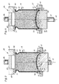
- a container 10 and a preform 10a for the container respectively.
- the preform and the container consist of crystallizable plastic material the preform and the container, respectively, comprising a container body 12, a sealed bottom portion 11a and 11, respectively, and an opening portion 13.
- the container body and preferably also the opening portion consist, as a rule, of monoaxially or biaxially oriented material.
- the opening portion has an opening edge 14 which, in the embodiment shown on the drawings, is arranged as an opening flange.
- the bottom portion 11, 11a is provided with a circumferentially disposed outer portion 19 forming one or more standing surfaces 18 for the container and a central portion 17 located inside thereof and at least in the container being displaced in relation to the standing surface or standing surfaces towards the opening portion of the container.
- the central portion consists substantially of amorphous material.
- substantially amorphous material is here taken to mean that the crystallization is less than 10 % and as a rule less than 5 %. It will be obvious to one skilled in the art that, in certain embodiments, the central portion 17 of the preform is located flush with the standing surface or standing surfaces of the bottom portion or, in certain embodiments, is located at a lower level.
- the outwardly facing surface of the bottom portion has reference numeral 15 and its inwardly facing surface has reference numeral 16.
- the preform 10a and the container 10, respectively, are carried by a step 53 of a circular or polygonal holder 50.
- the step is located between an upper defining surface 51 facing the centre axis 61 of the apparatus and a lower defining surface 52 facing the centre axis.
- the upper defining surface defines, towards the centre axis 61, a tube-like member 57 which is dimensioned so as to surround the bottom portion 11a, 11, of the preform and the container, respectively, and, in certain embodiments, also at least the lower portion of the container body 12.
- the tube-like member is of a sufficiently long axial extent to surround at least the major portion of the container body.
- the inner cross-sectional area of the tube-like member is adapted to the form (configuration) of the preform or the container, and is, for example, circular, elliptical, polygonal, etc.
- the tube-like member 57 is provided with a bevel 56 at its upper portion so as to facilitate placing of the container in the holder.
- the lower defining surface surrounds an aperture 54.
- the holder has a downwardly facing abutment surface 55 which rests against an abutment surface 45 on a substrate 40.
- the substrate 40 is provided with an aperture 43 with an upper surface 41 facing the centre axis and a lower surface 42 facing the centre axis, the lower surface being of smaller circumference than the upper.
- the transition between the two surfaces forms a step 45 which constitutes the previously mentioned abutment surface 45 of the substrate 40.
- the dimensions of the aperture 43 are adapted to the maximum size of the generally annular holder 50 which is employed in the embodiments contemplated here.
- each holder 50 has outer dimensions adapted to the dimensions of the aperture 43 of the substrate and inner dimensions adapted to the dimensions and designs of the contemplated preform and container, respectively.
- the annular holder is shown as placed in the aperture of the substrate without the employment of specific holding means.
- such means may be given varying design in response to the contemplated application.
- the mechanical tool is displaceable by drive means (not shown) by the intermediary of a lower shaft 21 to an upper position (cf. Figs. 2 and 7) and back to the position shown in Figs. 1 and 5.
- the mechanical tool is provided with an upwardly facing abutment surface 22 with a central portion 23 and an outer circumferential portion 24.
- the abutment surface merges, in an outer circumferential region, into a fitting or guiding surface 27 which forms a substantially vertically directed circumferential surface facing away from the centre axis 61 of the apparatus.
- the fitting surface is adapted to the lower defining surface 52 of the annular holder 50 facing the centre axis, so as to be displaceable to a position where the fitting surface 27 is surrounded by the lower defining surface 52 of the annular holder 50.
- the fitting surface merges into an outwardly directed abutment surface 25 which cooperates with the abutment surface 55 of the annular holder.
- the mechanical tool has a lower, outwardly facing defining surface 28 which connects to the abutment surface 25 of the mechanical tool and is dimensioned so as generally to fit into the aperture 43 of the substrate (cf. Fig. 2).
- Means 26 for raising the temperature of the abutment surface of the bottom forming device are included in the mechanical tool.
- the abutment surface 22 is of a convex form at least in its central region.
- an upper counter support 30 is displaceable, by means of an upper shaft 34, between a first position (cf. Fig. 1), where space is allowed to place the preform 10a in the holder 50, and a second position where said support rests against the opening edge 14 of the container (cf. Fig. 2).
- the counter support is provided with a circumferential abutment portion 31 with an abutment surface 32 for cooperation with the opening edge 14.
- a central connection portion 33 includes channels 35 which, with the counter support resting against the opening edge, communicate the space beneath the counter support with the ambient atmosphere.
- the central connection portion constitutes anchorage means for the upper shaft 34. It will be obvious to one skilled in the art that the upper counter support is, in certain embodiments, displaced laterally so as to permit placing of the preform in the annular holder 50.
- Figs. 3-7 illustrate an alternative embodiment of the present invention in which the upper counter surface 30 is replaced by a sealing member 80 disposed above the opening portion of the preform 10a and the container 10, respectively.
- the sealing member comprises a circumferential abutment portion 81, for example one or more heat-sealing jaws, welding jaws, etc., a central connection portion 83 and a drive shaft 84 connected to the central connection portion.
- the circumferential abutment portion is provided with one or more abutment surfaces 82 which are turned to face the opening edge of the container.
- the figures also show a seal 70, for example a lid, a wafer etc., provided with a gripping device 71.
- the abutment portion also includes means for sealingly connecting the seal to the opening portion of the container.
- the abutment portion includes a sonotrode for fixing the wafer to the opening portion by means of ultrasonic welding, while in other embodiments means 85 are provided for raising the temperature of the abutment surface 82 of the abutment portion, for example electrical heating coils or ducts for thermal medium.
- the sealing member 80 is displaceable between a first upper position (cf. Figs. 3 and 5), and a second lower position (cf. Figs. 4, 6 and 7), in which position the sealing member abuts against the wafer and urges this towards the opening portion of the container.
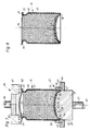
- Fig. 8 shows a section through the container 10 once the filling goods in the container have cooled.
- the preform and the container, respectively, are shown as having been supplied with filling goods 60.
- the preform 10a is placed in the holder 50 once it has already been filled with goods 60 or is filled with goods after being placed in the holder.
- the goods are generally supplied to the preform at a temperature in excess of 50°C, preferably in excess of 70°C and generally in excess of 90°C.
- the bottom forming tool 20 is subsequently displaced upwardly in Figs. 1 and 5 to assume that position which is shown in Figs. 2 and 7, respectively.
- the abutment surface 22 of the bottom forming tool is, in such instance, set at an elevated temperature, as a rule a temperature exceeding the glass transition temperature (Tg) of the material.
- the temperature of the abutment surface is adjusted by means of the heating device 26 at a level slightly in excess of the temperature at which the speed of the thermocrystallization of the plastic material is at its highest, preferably at a temperature exceeding this temperature by at least 5°C and generally exceeding this temperature by at least 10°C.
- Thermal energy from the filling goods is added to the thermal energy from the bottom forming tool and entails that the thermal plastic material of the bottom portion, on abutment against the abutment surface of the bottom forming tool, rapidly reaches a temperature above the Tg of the material. At this point, the material softens and reforming of the bottom portion is facilitated at the same time as the material thermally crystallizes.
- thermocrystallization takes place very slowly as long as the material temperature is less than 90-100°C, whereafter at increasing temperature the crystallization increases rapidly.
- the crystallization speed is also pressuredependent, but at those pressure forces which are relevant in the application of the present invention, the effects of the pressure forces on crystallization are essentially negligible, which entails that maximum crystallization speed will be obtained for PET if the material is at a temperature within the range of 135-145°C.
- the upper counter support 30 or the sealing member 80 is displaced into abutment against the opening portion and hereby ensures that the preform is held in place and that the abutment surface 22 of the bottom forming tool securely abuts against the bottom portion.
- the forming tool 20 thereafter returns to its lower position (cf. Fig. 1) once sufficient time has elapsed with the bottom forming tool in the upper position that the material in the bottom portion has achieved the desired crystallization.
- thermo crystallization is allowed to continue until such time as the material has a crystallization of at least approx. 15 %, generally at least approx. 20 % and, in a preferred embodiment, at least approx. 25 %.
- the upper counter support 30 is thereafter displaced from the position illustrated in Fig. 2 , whereupon the sealing member 80, once a closure 19, for example a wafer, has been placed over the opening of the container, is displaced from its initial position (cf. Fig. 3) to a working position (cf. Fig.
- the sealing member includes the sonitrode for ultrasonic welding, the joint being formed as a welding joint.
- connection means for fixedly securing the wafer to the opening portion are selected such that a relatively lengthy abutment of the abutment surface against the wafer and consequential heating thereof and of the opening portion do not entail any problems.
- the wafer On the reforming of the bottom portion, excess pressure arises within the container.
- the wafer (the lid) consists of resiliently yieldable material, for which reason the excess pressure entails that the wafer, in a central region, forms an outward bulge 72 (cf. Fig. 7).
- the bottom forming tool 20 In order to ensure that the bottom portion is capable of withstanding the excess pressure, the bottom forming tool 20 is retained in its upper position (cf. Fig. 7) for such a length of time that the above crystallization levels are achieved. Thereafter, the bottom forming tool and the sealing member return to their initial positions and the container is removed from the holder 50.
- Examples of pressure variations in the physical application of the present invention and employment of containers of PET are that the excess pressure within the container, after reforming of the bottom portion is allowed to reach 0.2 bar and that the dimensions of the container, the size of the space between the filling goods and the wafer and the material properties of the container are selected such that, when the container cools, the pressure is reduced within the container by approx. 0.2 bar, whereby it will be ensured that, at room temperature, largely the same pressure will prevail within the container as outside.
- the outward bulging 72 will disappear when the wafer returns to its original form (cf. Figs. 7 and 8).
- the size of the reduction of the filling space of the container entailed by reforming of the bottom portion is adapted such that, when the filling goods have cooled, a certain partial vacuum or excess pressure prevails in the container.
- the lid the wafer
- an outer protective lid is, as a rule, employed - this being dimensioned so as to withstand mechanical stresses in the form of jolts or jerks during transport and handling of the container.
- the wafer (the inner lid) is more elastic than the rest of the container, for which reason the partial vacuum will not entail undesirable deformation of the opening portion of the container, its body or bottom portion, a deformation which would result that the package as a whole be rejected by the consumer.
- Fig. 8 shows a container which has been sealed with the filling goods in the warm state, the bottom of the container being thereafter reformed and in which the temperature of the filling goods and the extent of the reforming have been adjusted so that the pressure reduction which occurs in the interior of the container in conjunction with the temperature reduction has entailed that the seal (wafer) 70 of the container has reassumed its original form and forms a substantially planar lid.
- the temperature of the abutment surface of the bottom shaping tool is selected, in certain embodiments, to be at relatively high levels.
- temperatures of up to approx. 220°C i.e. a temperature which is less than the melting temperature of the material by approx. 25°C, and at the same time achieve the sought-for crystallization levels in the material in the bottom portion.
- the advantage inherent in such high temperatures is that, after the crystallization, the material is mechanically stable up to very high temperatures.
- the substrate is disposed as a rotary table with a plurality of apertures 43 and annular holders 50 cooperating therewith.
Landscapes
- Engineering & Computer Science (AREA)
- Mechanical Engineering (AREA)
- Manufacturing & Machinery (AREA)
- Blow-Moulding Or Thermoforming Of Plastics Or The Like (AREA)
- Supplying Of Containers To The Packaging Station (AREA)
- Containers Having Bodies Formed In One Piece (AREA)
- Making Paper Articles (AREA)
- Catalysts (AREA)
- Curing Cements, Concrete, And Artificial Stone (AREA)
- Processing And Handling Of Plastics And Other Materials For Molding In General (AREA)
- Filling Of Jars Or Cans And Processes For Cleaning And Sealing Jars (AREA)
Applications Claiming Priority (3)
| Application Number | Priority Date | Filing Date | Title |
|---|---|---|---|
| SE8804677A SE462591B (sv) | 1988-12-29 | 1988-12-29 | Saett och anordning foer framstaellning av behaallare |
| SE8804677 | 1988-12-29 | ||
| PCT/SE1989/000747 WO1990007451A1 (en) | 1988-12-29 | 1989-12-22 | A method and an apparatus for producing containers |
Publications (2)
| Publication Number | Publication Date |
|---|---|
| EP0402445A1 EP0402445A1 (en) | 1990-12-19 |
| EP0402445B1 true EP0402445B1 (en) | 1995-02-15 |
Family
ID=20374346
Family Applications (1)
| Application Number | Title | Priority Date | Filing Date |
|---|---|---|---|
| EP90901062A Expired - Lifetime EP0402445B1 (en) | 1988-12-29 | 1989-12-22 | A method and an apparatus for producing containers |
Country Status (13)
| Country | Link |
|---|---|
| US (1) | US5090180A (da) |
| EP (1) | EP0402445B1 (da) |
| JP (1) | JPH03504220A (da) |
| AT (1) | ATE118418T1 (da) |
| AU (1) | AU620199B2 (da) |
| BR (1) | BR8907288A (da) |
| CA (1) | CA2006790A1 (da) |
| DE (1) | DE68921199T2 (da) |
| DK (1) | DK168328B1 (da) |
| ES (1) | ES2068381T3 (da) |
| FI (1) | FI89342C (da) |
| SE (1) | SE462591B (da) |
| WO (1) | WO1990007451A1 (da) |
Families Citing this family (65)
| Publication number | Priority date | Publication date | Assignee | Title |
|---|---|---|---|---|
| FR2666047A1 (fr) * | 1990-08-24 | 1992-02-28 | Guiard Jacques | Procede d'obtention de poudres compactees conditionnees dans des recipients; installation pour la mise en óoeuvre de ce procede; recipient destine au conditionnement de poudres compactees. |
| US5482204A (en) * | 1994-03-21 | 1996-01-09 | International Paper Company | Carton bottom sealer |
| IT1305240B1 (it) * | 1998-06-04 | 2001-04-19 | Burgopack Stampa Trasformazione Imballaggi Spa | Un procedimento per realizzare confezioni a tubo in materialeflessibile, una apparecchiatura per effettuare il procedimento ed una |
| US8381940B2 (en) | 2002-09-30 | 2013-02-26 | Co2 Pac Limited | Pressure reinforced plastic container having a moveable pressure panel and related method of processing a plastic container |
| US8127955B2 (en) | 2000-08-31 | 2012-03-06 | John Denner | Container structure for removal of vacuum pressure |
| US7900425B2 (en) * | 2005-10-14 | 2011-03-08 | Graham Packaging Company, L.P. | Method for handling a hot-filled container having a moveable portion to reduce a portion of a vacuum created therein |
| US8584879B2 (en) * | 2000-08-31 | 2013-11-19 | Co2Pac Limited | Plastic container having a deep-set invertible base and related methods |
| US7543713B2 (en) * | 2001-04-19 | 2009-06-09 | Graham Packaging Company L.P. | Multi-functional base for a plastic, wide-mouth, blow-molded container |
| WO2005012091A2 (en) | 2003-07-30 | 2005-02-10 | Graham Packaging Company, L.P. | Container handling system |
| NZ521694A (en) | 2002-09-30 | 2005-05-27 | Co2 Pac Ltd | Container structure for removal of vacuum pressure |
| US10435223B2 (en) | 2000-08-31 | 2019-10-08 | Co2Pac Limited | Method of handling a plastic container having a moveable base |
| TWI228476B (en) * | 2000-08-31 | 2005-03-01 | Co2 Pac Ltd | Semi-rigid collapsible container |
| US10246238B2 (en) | 2000-08-31 | 2019-04-02 | Co2Pac Limited | Plastic container having a deep-set invertible base and related methods |
| WO2002085755A1 (en) | 2001-04-19 | 2002-10-31 | Graham Packaging Company, L.P. | Multi-functional base for a plastic wide-mouth, blow-molded container |
| USH2088H1 (en) * | 2001-06-29 | 2003-11-04 | Eastman Chemical Company | Method for reducing plate-out in a stretch blow molded container |
| USH2132H1 (en) | 2001-06-29 | 2005-11-01 | Eastman Chemical Company | Polyester containers having a reduced coefficient of friction |
| US9969517B2 (en) | 2002-09-30 | 2018-05-15 | Co2Pac Limited | Systems and methods for handling plastic containers having a deep-set invertible base |
| DE502004012264D1 (de) * | 2003-07-30 | 2011-04-14 | Rm Beteiligungs Ag | Kunststoffgetränkeflasche mit kapsel |
| US6915623B2 (en) * | 2003-08-14 | 2005-07-12 | Ethicon, Inc. | Method for assembling a package for sutures |
| JP4769791B2 (ja) * | 2004-03-11 | 2011-09-07 | グラハム パッケージング カンパニー,エル ピー | プラスチック容器運搬方法 |
| US10611544B2 (en) | 2004-07-30 | 2020-04-07 | Co2Pac Limited | Method of handling a plastic container having a moveable base |
| TWI375641B (en) * | 2004-12-20 | 2012-11-01 | Co2 Pac Ltd | A method of processing a container and base cup structure for removal of vacuum pressure |
| US8075833B2 (en) * | 2005-04-15 | 2011-12-13 | Graham Packaging Company L.P. | Method and apparatus for manufacturing blow molded containers |
| US8017065B2 (en) * | 2006-04-07 | 2011-09-13 | Graham Packaging Company L.P. | System and method for forming a container having a grip region |
| US7799264B2 (en) | 2006-03-15 | 2010-09-21 | Graham Packaging Company, L.P. | Container and method for blowmolding a base in a partial vacuum pressure reduction setup |
| US8747727B2 (en) | 2006-04-07 | 2014-06-10 | Graham Packaging Company L.P. | Method of forming container |
| US9707711B2 (en) | 2006-04-07 | 2017-07-18 | Graham Packaging Company, L.P. | Container having outwardly blown, invertible deep-set grips |
| US8528304B2 (en) * | 2006-07-03 | 2013-09-10 | Graham Packaging Company, L.P. | Method and device for producing content filling bottle |
| US11897656B2 (en) | 2007-02-09 | 2024-02-13 | Co2Pac Limited | Plastic container having a movable base |
| US11731823B2 (en) | 2007-02-09 | 2023-08-22 | Co2Pac Limited | Method of handling a plastic container having a moveable base |
| FR2922147B1 (fr) * | 2007-10-10 | 2010-01-01 | Tecsor | Procede de fabrication d'un contenant a paroi mince, procede de mise en pression de ce contenant |
| FR2922151B1 (fr) * | 2007-10-10 | 2010-01-01 | Tecsor | Procede de mise en pression de l'interieur d'un contenant a paroi mince, contenant sous pression obtenu |
| US7614202B2 (en) * | 2007-11-27 | 2009-11-10 | Atlas Vac Machine Co., Llc | Sealer and interchangeable tooling therefor |
| US8142827B2 (en) * | 2008-04-16 | 2012-03-27 | Georgia Crown Distributing Co. | Packaged bottle beverage having an ingredient release closure with improved additive release and method and apparatus thereof |
| US8627944B2 (en) * | 2008-07-23 | 2014-01-14 | Graham Packaging Company L.P. | System, apparatus, and method for conveying a plurality of containers |
| FR2934568B1 (fr) * | 2008-07-29 | 2010-09-17 | Tecsor | Procede de traitement d'un contenant a paroi mince en matiere plastique, rempli a chaud et dispositif associe |
| US8636944B2 (en) | 2008-12-08 | 2014-01-28 | Graham Packaging Company L.P. | Method of making plastic container having a deep-inset base |
| CA2748589C (en) * | 2008-12-31 | 2018-05-15 | Plastipak Packaging, Inc. | Hot-fillable plastic container with flexible base feature |
| US7926243B2 (en) | 2009-01-06 | 2011-04-19 | Graham Packaging Company, L.P. | Method and system for handling containers |
| US20130283729A1 (en) * | 2009-02-10 | 2013-10-31 | Plastipak Packaging, Inc. | System and method for pressurizing a plastic container |
| TR201904887T4 (tr) * | 2009-02-10 | 2019-05-21 | Plastipack Packaging Inc | bir plastik kabın basınçlandırılmasına yönelik bir yöntem ve sistem. |
| US9731850B2 (en) * | 2009-02-10 | 2017-08-15 | Plastipak Packaging, Inc. | System and method for pressurizing a plastic container |
| TWI570024B (zh) * | 2009-05-13 | 2017-02-11 | 四國化工機股份有限公司 | Method for manufacturing food - filled sealed containers |
| US8454292B2 (en) * | 2009-05-14 | 2013-06-04 | Crown Packaging Technology, Inc. | Method of forming a can end having a moveable portion |
| WO2012006739A1 (en) | 2010-07-16 | 2012-01-19 | Cascades Canada Ulc | Plastic container |
| US8962114B2 (en) | 2010-10-30 | 2015-02-24 | Graham Packaging Company, L.P. | Compression molded preform for forming invertible base hot-fill container, and systems and methods thereof |
| US9133006B2 (en) | 2010-10-31 | 2015-09-15 | Graham Packaging Company, L.P. | Systems, methods, and apparatuses for cooling hot-filled containers |
| US9150320B2 (en) | 2011-08-15 | 2015-10-06 | Graham Packaging Company, L.P. | Plastic containers having base configurations with up-stand walls having a plurality of rings, and systems, methods, and base molds thereof |
| US9994378B2 (en) | 2011-08-15 | 2018-06-12 | Graham Packaging Company, L.P. | Plastic containers, base configurations for plastic containers, and systems, methods, and base molds thereof |
| US10532848B2 (en) * | 2011-08-31 | 2020-01-14 | Amcor Rigid Plastics Usa, Llc | Lightweight container base |
| US10538357B2 (en) | 2011-08-31 | 2020-01-21 | Amcor Rigid Plastics Usa, Llc | Lightweight container base |
| US8919587B2 (en) | 2011-10-03 | 2014-12-30 | Graham Packaging Company, L.P. | Plastic container with angular vacuum panel and method of same |
| US9522508B2 (en) * | 2011-11-15 | 2016-12-20 | Amcor Limited | Plural blow utilization of counter stretch rod and/or base pushup |
| ITRE20110111A1 (it) * | 2011-12-23 | 2013-06-24 | Alfa Laval Parma S R L | Macchina asettica di riempimento |
| US12577027B2 (en) | 2012-03-08 | 2026-03-17 | Co2Pac Limited | Method of processing a plastic container to increase internal pressure |
| WO2014005023A1 (en) * | 2012-06-28 | 2014-01-03 | Plastipak Packaging, Inc. | System and method for pressurizing a plastic container |
| PL2885211T3 (pl) * | 2012-08-14 | 2019-04-30 | Altria Client Services Llc | System kierowania do pojemnika z kontrolą wagi on-line i powiązany sposób |
| DE102012017364A1 (de) * | 2012-09-01 | 2014-03-06 | E-proPlast GmbH | Vorrichtung und Verfahren zur dauerhaften Umformung von PET-Flaschen oder PET-Behältern nach der Heißabfüllung |
| DE102012108928A1 (de) * | 2012-09-21 | 2014-03-27 | Krones Ag | Verfahren und Vorrichtung zum Transportieren von mit Flüssigkeit gefüllten Behältern |
| US9022776B2 (en) | 2013-03-15 | 2015-05-05 | Graham Packaging Company, L.P. | Deep grip mechanism within blow mold hanger and related methods and bottles |
| US9254937B2 (en) | 2013-03-15 | 2016-02-09 | Graham Packaging Company, L.P. | Deep grip mechanism for blow mold and related methods and bottles |
| CN105492369B (zh) * | 2013-09-19 | 2017-10-31 | 西德尔合作公司 | 用于处理具有可倒置隔膜的填充容器的机器和方法 |
| DE102016202908A1 (de) * | 2016-02-25 | 2017-08-31 | Krones Ag | Verfahren zur Bodenausformung heißabgefüllter Behälter |
| CA3076584A1 (en) * | 2017-09-21 | 2019-03-28 | Amcor Rigid Packaging Usa, Llc | Method of inverting container base prior to cooling |
| USD1126002S1 (en) | 2024-10-08 | 2026-05-12 | Co2Pac Limited | Container |
Family Cites Families (20)
| Publication number | Priority date | Publication date | Assignee | Title |
|---|---|---|---|---|
| US2124959A (en) * | 1936-08-08 | 1938-07-26 | Vogel William Martin | Method of filling and closing cans |
| US3117873A (en) * | 1959-03-20 | 1964-01-14 | Continental Can Co | Package and method of forming same |
| US3104506A (en) * | 1960-10-26 | 1963-09-24 | Howard A Rohdin | Method of sealing blister type packages |
| US3103089A (en) * | 1961-01-23 | 1963-09-10 | Lever Brothers Ltd | Method of filling containers |
| US3342009A (en) * | 1962-06-11 | 1967-09-19 | Philip H Allen | Method of providing a head space within a filled container |
| US3353325A (en) * | 1964-02-03 | 1967-11-21 | Mayer & Co Inc O | Packaging of free flowing materials |
| GB1154617A (en) * | 1966-03-11 | 1969-06-11 | Cornelius Co | Improvements in or relating to Making and Filling Containers with a Liquid, For Example a Beverage. |
| US3449183A (en) * | 1966-08-11 | 1969-06-10 | Koehler Dayton | Thermoplastic sealing apparatus and method |
| US3492773A (en) * | 1967-01-25 | 1970-02-03 | Anderson Bros Mfg Co | Method of vacuum packaging |
| US3521422A (en) * | 1967-10-24 | 1970-07-21 | Craft Master Corp | Method for closing open-topped liquid containers |
| US3517475A (en) * | 1968-04-18 | 1970-06-30 | American Can Co | Method of packaging |
| JPS5819535B2 (ja) * | 1979-04-16 | 1983-04-19 | 本州製紙株式会社 | 密封容器のシ−ル方法 |
| SE424420B (sv) * | 1979-06-11 | 1982-07-19 | Plm Ab | Framstellning av artiklar genom dragning och blasning |
| US4684025A (en) * | 1986-01-30 | 1987-08-04 | The Procter & Gamble Company | Shaped thermoformed flexible film container for granular products and method and apparatus for making the same |
| JPS62260619A (ja) * | 1986-05-06 | 1987-11-12 | プリマハム株式会社 | 食品の盛上げ包装方法 |
| FR2600305B1 (fr) * | 1986-06-23 | 1989-06-30 | Vulliez Patrick | Procede d'obtention de produits alimentaires emballes de facon etanche dans des recipients, installation pour la mise en oeuvre de ce procede: recipient destine en particulier a l'emballage etanche de produits alimentaires |
| SE505485C2 (sv) * | 1987-03-17 | 1997-09-08 | Plm Ab | Sätt och anordning att kristallisera och forma bottenpartiet hos en kopp eller koppliknande föremål |
| US4835942A (en) * | 1987-06-26 | 1989-06-06 | Skrmetta Raphael Q | Seafood vacuum-pack system |
| US4967538A (en) * | 1988-01-29 | 1990-11-06 | Aluminum Company Of America | Inwardly reformable endwall for a container and a method of packaging a product in the container |
| US4807424A (en) * | 1988-03-02 | 1989-02-28 | Raque Food Systems, Inc. | Packaging device and method |
-
1988
- 1988-12-29 SE SE8804677A patent/SE462591B/sv not_active IP Right Cessation
-
1989
- 1989-12-22 BR BR898907288A patent/BR8907288A/pt unknown
- 1989-12-22 ES ES90901062T patent/ES2068381T3/es not_active Expired - Lifetime
- 1989-12-22 EP EP90901062A patent/EP0402445B1/en not_active Expired - Lifetime
- 1989-12-22 DE DE68921199T patent/DE68921199T2/de not_active Expired - Fee Related
- 1989-12-22 AU AU48341/90A patent/AU620199B2/en not_active Ceased
- 1989-12-22 AT AT90901062T patent/ATE118418T1/de not_active IP Right Cessation
- 1989-12-22 JP JP2501817A patent/JPH03504220A/ja active Pending
- 1989-12-22 US US07/571,605 patent/US5090180A/en not_active Expired - Fee Related
- 1989-12-22 WO PCT/SE1989/000747 patent/WO1990007451A1/en not_active Ceased
- 1989-12-28 CA CA002006790A patent/CA2006790A1/en not_active Abandoned
-
1990
- 1990-08-27 FI FI904225A patent/FI89342C/fi not_active IP Right Cessation
- 1990-08-28 DK DK205690A patent/DK168328B1/da not_active IP Right Cessation
Also Published As
| Publication number | Publication date |
|---|---|
| DK168328C (da) | 1994-03-14 |
| SE8804677D0 (sv) | 1988-12-29 |
| FI904225A0 (fi) | 1990-08-27 |
| DK168328B1 (da) | 1994-03-14 |
| BR8907288A (pt) | 1991-03-12 |
| AU4834190A (en) | 1990-08-01 |
| WO1990007451A1 (en) | 1990-07-12 |
| DE68921199D1 (de) | 1995-03-23 |
| CA2006790A1 (en) | 1990-06-29 |
| JPH03504220A (ja) | 1991-09-19 |
| SE462591B (sv) | 1990-07-23 |
| ATE118418T1 (de) | 1995-03-15 |
| SE8804677L (sv) | 1990-06-30 |
| AU620199B2 (en) | 1992-02-13 |
| DE68921199T2 (de) | 1995-06-14 |
| FI89342C (fi) | 1993-09-27 |
| FI89342B (fi) | 1993-06-15 |
| ES2068381T3 (es) | 1995-04-16 |
| DK205690A (da) | 1990-08-28 |
| DK205690D0 (da) | 1990-08-28 |
| EP0402445A1 (en) | 1990-12-19 |
| US5090180A (en) | 1992-02-25 |
Similar Documents
| Publication | Publication Date | Title |
|---|---|---|
| AU620199B2 (en) | A method and an apparatus for producing containers | |
| US6763968B1 (en) | Base portion of a plastic container | |
| US8276774B2 (en) | Container base structure responsive to vacuum related forces | |
| US7451886B2 (en) | Container base structure responsive to vacuum related forces | |
| EP1893496B1 (en) | Container base structure responsive to vacuum related forces | |
| JP2688089B2 (ja) | レトルトキャニングで用いるのに適した容器 | |
| US8047389B2 (en) | Semi-rigid collapsible container | |
| JP6930263B2 (ja) | ポリエステル系樹脂製容器の製造方法、及びブロー成形型 | |
| CN104349993A (zh) | 可甑馏封装物 | |
| JP4276823B2 (ja) | 耐熱性を有するプラスチック製のカップ状容器およびその一次成形品 | |
| EP1772251B1 (en) | Polyester container excellent in resistance to heat and impact, and method for production thereof | |
| EP0519928B1 (en) | Method and apparatus for manufacturing of a container | |
| JP4561519B2 (ja) | フランジ部の加熱処理方法、フランジ部の加熱処理装置及びフランジ付き樹脂製容器の製造方法 | |
| US20200270109A1 (en) | Method of inverting container base prior to cooling | |
| JP4634483B2 (ja) | 耐熱性を有するプラスチック製のカップ状容器およびその一次成形品 | |
| NO174921B (no) | Fremgangsmåte og anordning for fremstilling av beholder | |
| US20250282600A1 (en) | Method Of Inverting Container Base Prior To Cooling | |
| WO1991012951A1 (en) | A container with substantially planar side surfaces | |
| JPH0755142B2 (ja) | 包装製品およびその製造方法 |
Legal Events
| Date | Code | Title | Description |
|---|---|---|---|
| PUAI | Public reference made under article 153(3) epc to a published international application that has entered the european phase |
Free format text: ORIGINAL CODE: 0009012 |
|
| AK | Designated contracting states |
Kind code of ref document: A1 Designated state(s): AT BE CH DE ES FR GB IT LI LU NL SE |
|
| 17P | Request for examination filed |
Effective date: 19901218 |
|
| 17Q | First examination report despatched |
Effective date: 19921109 |
|
| RAP1 | Party data changed (applicant data changed or rights of an application transferred) |
Owner name: PLM AB |
|
| GRAA | (expected) grant |
Free format text: ORIGINAL CODE: 0009210 |
|
| AK | Designated contracting states |
Kind code of ref document: B1 Designated state(s): AT BE CH DE ES FR GB IT LI LU NL SE |
|
| REF | Corresponds to: |
Ref document number: 118418 Country of ref document: AT Date of ref document: 19950315 Kind code of ref document: T |
|
| ITF | It: translation for a ep patent filed | ||
| REF | Corresponds to: |
Ref document number: 68921199 Country of ref document: DE Date of ref document: 19950323 |
|
| REG | Reference to a national code |
Ref country code: ES Ref legal event code: FG2A Ref document number: 2068381 Country of ref document: ES Kind code of ref document: T3 |
|
| ET | Fr: translation filed | ||
| PLBE | No opposition filed within time limit |
Free format text: ORIGINAL CODE: 0009261 |
|
| STAA | Information on the status of an ep patent application or granted ep patent |
Free format text: STATUS: NO OPPOSITION FILED WITHIN TIME LIMIT |
|
| 26N | No opposition filed | ||
| PGFP | Annual fee paid to national office [announced via postgrant information from national office to epo] |
Ref country code: AT Payment date: 19971205 Year of fee payment: 9 |
|
| PGFP | Annual fee paid to national office [announced via postgrant information from national office to epo] |
Ref country code: CH Payment date: 19971211 Year of fee payment: 9 |
|
| PGFP | Annual fee paid to national office [announced via postgrant information from national office to epo] |
Ref country code: ES Payment date: 19981204 Year of fee payment: 10 |
|
| PGFP | Annual fee paid to national office [announced via postgrant information from national office to epo] |
Ref country code: LU Payment date: 19981207 Year of fee payment: 10 |
|
| PGFP | Annual fee paid to national office [announced via postgrant information from national office to epo] |
Ref country code: NL Payment date: 19981209 Year of fee payment: 10 |
|
| PGFP | Annual fee paid to national office [announced via postgrant information from national office to epo] |
Ref country code: BE Payment date: 19981216 Year of fee payment: 10 |
|
| PG25 | Lapsed in a contracting state [announced via postgrant information from national office to epo] |
Ref country code: AT Free format text: LAPSE BECAUSE OF NON-PAYMENT OF DUE FEES Effective date: 19981222 |
|
| PG25 | Lapsed in a contracting state [announced via postgrant information from national office to epo] |
Ref country code: LI Free format text: LAPSE BECAUSE OF NON-PAYMENT OF DUE FEES Effective date: 19981231 Ref country code: CH Free format text: LAPSE BECAUSE OF NON-PAYMENT OF DUE FEES Effective date: 19981231 |
|
| REG | Reference to a national code |
Ref country code: CH Ref legal event code: PL |
|
| PG25 | Lapsed in a contracting state [announced via postgrant information from national office to epo] |
Ref country code: LU Free format text: LAPSE BECAUSE OF NON-PAYMENT OF DUE FEES Effective date: 19991222 |
|
| PG25 | Lapsed in a contracting state [announced via postgrant information from national office to epo] |
Ref country code: BE Free format text: LAPSE BECAUSE OF NON-PAYMENT OF DUE FEES Effective date: 19991231 |
|
| BERE | Be: lapsed |
Owner name: PLM A.B. Effective date: 19991231 |
|
| PG25 | Lapsed in a contracting state [announced via postgrant information from national office to epo] |
Ref country code: NL Free format text: LAPSE BECAUSE OF NON-PAYMENT OF DUE FEES Effective date: 20000701 |
|
| NLV4 | Nl: lapsed or anulled due to non-payment of the annual fee |
Effective date: 20000701 |
|
| PGFP | Annual fee paid to national office [announced via postgrant information from national office to epo] |
Ref country code: GB Payment date: 20001127 Year of fee payment: 12 |
|
| PGFP | Annual fee paid to national office [announced via postgrant information from national office to epo] |
Ref country code: SE Payment date: 20001201 Year of fee payment: 12 |
|
| PGFP | Annual fee paid to national office [announced via postgrant information from national office to epo] |
Ref country code: DE Payment date: 20001206 Year of fee payment: 12 |
|
| PGFP | Annual fee paid to national office [announced via postgrant information from national office to epo] |
Ref country code: FR Payment date: 20001207 Year of fee payment: 12 |
|
| PG25 | Lapsed in a contracting state [announced via postgrant information from national office to epo] |
Ref country code: ES Free format text: LAPSE BECAUSE OF NON-PAYMENT OF DUE FEES Effective date: 20001223 |
|
| PG25 | Lapsed in a contracting state [announced via postgrant information from national office to epo] |
Ref country code: GB Free format text: LAPSE BECAUSE OF NON-PAYMENT OF DUE FEES Effective date: 20011222 |
|
| PG25 | Lapsed in a contracting state [announced via postgrant information from national office to epo] |
Ref country code: SE Free format text: LAPSE BECAUSE OF NON-PAYMENT OF DUE FEES Effective date: 20011223 |
|
| REG | Reference to a national code |
Ref country code: GB Ref legal event code: IF02 |
|
| PG25 | Lapsed in a contracting state [announced via postgrant information from national office to epo] |
Ref country code: DE Free format text: LAPSE BECAUSE OF NON-PAYMENT OF DUE FEES Effective date: 20020702 |
|
| EUG | Se: european patent has lapsed |
Ref document number: 90901062.1 |
|
| GBPC | Gb: european patent ceased through non-payment of renewal fee |
Effective date: 20011222 |
|
| PG25 | Lapsed in a contracting state [announced via postgrant information from national office to epo] |
Ref country code: FR Free format text: LAPSE BECAUSE OF NON-PAYMENT OF DUE FEES Effective date: 20020830 |
|
| REG | Reference to a national code |
Ref country code: FR Ref legal event code: ST |
|
| REG | Reference to a national code |
Ref country code: ES Ref legal event code: FD2A Effective date: 20010113 |
|
| PG25 | Lapsed in a contracting state [announced via postgrant information from national office to epo] |
Ref country code: IT Free format text: LAPSE BECAUSE OF NON-PAYMENT OF DUE FEES Effective date: 20051222 |