EP1772251B1 - Polyester container excellent in resistance to heat and impact, and method for production thereof - Google Patents
Polyester container excellent in resistance to heat and impact, and method for production thereof Download PDFInfo
- Publication number
- EP1772251B1 EP1772251B1 EP05767371.7A EP05767371A EP1772251B1 EP 1772251 B1 EP1772251 B1 EP 1772251B1 EP 05767371 A EP05767371 A EP 05767371A EP 1772251 B1 EP1772251 B1 EP 1772251B1
- Authority
- EP
- European Patent Office
- Prior art keywords
- flange
- heat
- preform
- container
- cooling
- Prior art date
- Legal status (The legal status is an assumption and is not a legal conclusion. Google has not performed a legal analysis and makes no representation as to the accuracy of the status listed.)
- Not-in-force
Links
- 229920000728 polyester Polymers 0.000 title claims description 28
- 238000004519 manufacturing process Methods 0.000 title claims description 19
- 238000001816 cooling Methods 0.000 claims description 62
- 229910052751 metal Inorganic materials 0.000 claims description 35
- 239000002184 metal Substances 0.000 claims description 35
- 238000010438 heat treatment Methods 0.000 claims description 27
- 238000002347 injection Methods 0.000 claims description 27
- 239000007924 injection Substances 0.000 claims description 27
- 239000011324 bead Substances 0.000 claims description 26
- 238000009998 heat setting Methods 0.000 claims description 21
- 238000000034 method Methods 0.000 claims description 21
- 229920006230 thermoplastic polyester resin Polymers 0.000 claims description 9
- 238000007664 blowing Methods 0.000 claims description 2
- 239000012530 fluid Substances 0.000 claims description 2
- 238000002425 crystallisation Methods 0.000 description 21
- 230000035939 shock Effects 0.000 description 18
- -1 polyethylene terephthalate Polymers 0.000 description 14
- 230000008025 crystallization Effects 0.000 description 9
- 229920000139 polyethylene terephthalate Polymers 0.000 description 9
- 239000005020 polyethylene terephthalate Substances 0.000 description 9
- 230000009477 glass transition Effects 0.000 description 8
- 229920005989 resin Polymers 0.000 description 7
- 239000011347 resin Substances 0.000 description 7
- 230000007423 decrease Effects 0.000 description 6
- 230000000694 effects Effects 0.000 description 6
- 239000007789 gas Substances 0.000 description 6
- 238000007789 sealing Methods 0.000 description 6
- 230000015572 biosynthetic process Effects 0.000 description 4
- 230000000052 comparative effect Effects 0.000 description 4
- QQVIHTHCMHWDBS-UHFFFAOYSA-N isophthalic acid Chemical compound OC(=O)C1=CC=CC(C(O)=O)=C1 QQVIHTHCMHWDBS-UHFFFAOYSA-N 0.000 description 4
- 229920001707 polybutylene terephthalate Polymers 0.000 description 4
- 235000013361 beverage Nutrition 0.000 description 3
- 238000000071 blow moulding Methods 0.000 description 3
- 238000000326 densiometry Methods 0.000 description 3
- 235000013305 food Nutrition 0.000 description 3
- QQVIHTHCMHWDBS-UHFFFAOYSA-L isophthalate(2-) Chemical compound [O-]C(=O)C1=CC=CC(C([O-])=O)=C1 QQVIHTHCMHWDBS-UHFFFAOYSA-L 0.000 description 3
- 238000002844 melting Methods 0.000 description 3
- 230000008018 melting Effects 0.000 description 3
- QPFMBZIOSGYJDE-UHFFFAOYSA-N 1,1,2,2-tetrachloroethane Chemical compound ClC(Cl)C(Cl)Cl QPFMBZIOSGYJDE-UHFFFAOYSA-N 0.000 description 2
- CURLTUGMZLYLDI-UHFFFAOYSA-N Carbon dioxide Chemical compound O=C=O CURLTUGMZLYLDI-UHFFFAOYSA-N 0.000 description 2
- WNLRTRBMVRJNCN-UHFFFAOYSA-L adipate(2-) Chemical compound [O-]C(=O)CCCCC([O-])=O WNLRTRBMVRJNCN-UHFFFAOYSA-L 0.000 description 2
- 229910052782 aluminium Inorganic materials 0.000 description 2
- XAGFODPZIPBFFR-UHFFFAOYSA-N aluminium Chemical compound [Al] XAGFODPZIPBFFR-UHFFFAOYSA-N 0.000 description 2
- WERYXYBDKMZEQL-UHFFFAOYSA-N butane-1,4-diol Chemical compound OCCCCO WERYXYBDKMZEQL-UHFFFAOYSA-N 0.000 description 2
- 235000011089 carbon dioxide Nutrition 0.000 description 2
- 238000004891 communication Methods 0.000 description 2
- 239000002826 coolant Substances 0.000 description 2
- 239000013078 crystal Substances 0.000 description 2
- 230000001747 exhibiting effect Effects 0.000 description 2
- 238000005243 fluidization Methods 0.000 description 2
- 239000011888 foil Substances 0.000 description 2
- 230000000977 initiatory effect Effects 0.000 description 2
- 239000000314 lubricant Substances 0.000 description 2
- 229920000573 polyethylene Polymers 0.000 description 2
- 238000002407 reforming Methods 0.000 description 2
- 230000000087 stabilizing effect Effects 0.000 description 2
- 230000008093 supporting effect Effects 0.000 description 2
- 229920005992 thermoplastic resin Polymers 0.000 description 2
- MMINFSMURORWKH-UHFFFAOYSA-N 3,6-dioxabicyclo[6.2.2]dodeca-1(10),8,11-triene-2,7-dione Chemical group O=C1OCCOC(=O)C2=CC=C1C=C2 MMINFSMURORWKH-UHFFFAOYSA-N 0.000 description 1
- WSQZNZLOZXSBHA-UHFFFAOYSA-N 3,8-dioxabicyclo[8.2.2]tetradeca-1(12),10,13-triene-2,9-dione Chemical compound O=C1OCCCCOC(=O)C2=CC=C1C=C2 WSQZNZLOZXSBHA-UHFFFAOYSA-N 0.000 description 1
- IJGRMHOSHXDMSA-UHFFFAOYSA-N Atomic nitrogen Chemical compound N#N IJGRMHOSHXDMSA-UHFFFAOYSA-N 0.000 description 1
- ISWSIDIOOBJBQZ-UHFFFAOYSA-N Phenol Chemical compound OC1=CC=CC=C1 ISWSIDIOOBJBQZ-UHFFFAOYSA-N 0.000 description 1
- 239000004698 Polyethylene Substances 0.000 description 1
- 229910000831 Steel Inorganic materials 0.000 description 1
- YIMQCDZDWXUDCA-UHFFFAOYSA-N [4-(hydroxymethyl)cyclohexyl]methanol Chemical compound OCC1CCC(CO)CC1 YIMQCDZDWXUDCA-UHFFFAOYSA-N 0.000 description 1
- 239000006096 absorbing agent Substances 0.000 description 1
- 239000003963 antioxidant agent Substances 0.000 description 1
- 230000003078 antioxidant effect Effects 0.000 description 1
- 239000002216 antistatic agent Substances 0.000 description 1
- 239000003518 caustics Substances 0.000 description 1
- 239000003795 chemical substances by application Substances 0.000 description 1
- 239000003086 colorant Substances 0.000 description 1
- 239000000470 constituent Substances 0.000 description 1
- 239000000498 cooling water Substances 0.000 description 1
- 238000001938 differential scanning calorimetry curve Methods 0.000 description 1
- 229910001873 dinitrogen Inorganic materials 0.000 description 1
- 230000003028 elevating effect Effects 0.000 description 1
- 238000011156 evaluation Methods 0.000 description 1
- 230000002349 favourable effect Effects 0.000 description 1
- 239000000945 filler Substances 0.000 description 1
- 239000000796 flavoring agent Substances 0.000 description 1
- 235000019634 flavors Nutrition 0.000 description 1
- 238000007667 floating Methods 0.000 description 1
- 239000012760 heat stabilizer Substances 0.000 description 1
- NJBYKVMTNHHDJE-UHFFFAOYSA-N heptane;tetrachloromethane Chemical compound ClC(Cl)(Cl)Cl.CCCCCCC NJBYKVMTNHHDJE-UHFFFAOYSA-N 0.000 description 1
- 230000001771 impaired effect Effects 0.000 description 1
- 230000001976 improved effect Effects 0.000 description 1
- 239000007769 metal material Substances 0.000 description 1
- 239000012046 mixed solvent Substances 0.000 description 1
- 238000002156 mixing Methods 0.000 description 1
- 239000000203 mixture Substances 0.000 description 1
- RXOHFPCZGPKIRD-UHFFFAOYSA-N naphthalene-2,6-dicarboxylic acid Chemical compound C1=C(C(O)=O)C=CC2=CC(C(=O)O)=CC=C21 RXOHFPCZGPKIRD-UHFFFAOYSA-N 0.000 description 1
- 230000002093 peripheral effect Effects 0.000 description 1
- 229920000747 poly(lactic acid) Polymers 0.000 description 1
- 229920000058 polyacrylate Polymers 0.000 description 1
- 229920000515 polycarbonate Polymers 0.000 description 1
- 239000004417 polycarbonate Substances 0.000 description 1
- 229920001225 polyester resin Polymers 0.000 description 1
- 239000004645 polyester resin Substances 0.000 description 1
- 239000004626 polylactic acid Substances 0.000 description 1
- 238000004321 preservation Methods 0.000 description 1
- 230000005855 radiation Effects 0.000 description 1
- 230000003014 reinforcing effect Effects 0.000 description 1
- 230000002040 relaxant effect Effects 0.000 description 1
- 229920002545 silicone oil Polymers 0.000 description 1
- 239000002356 single layer Substances 0.000 description 1
- 239000002904 solvent Substances 0.000 description 1
- 230000006641 stabilisation Effects 0.000 description 1
- 238000011105 stabilization Methods 0.000 description 1
- 229910001220 stainless steel Inorganic materials 0.000 description 1
- 239000010935 stainless steel Substances 0.000 description 1
- 239000010959 steel Substances 0.000 description 1
- 229920001169 thermoplastic Polymers 0.000 description 1
- 229920002725 thermoplastic elastomer Polymers 0.000 description 1
- 239000004416 thermosoftening plastic Substances 0.000 description 1
- XLYOFNOQVPJJNP-UHFFFAOYSA-N water Substances O XLYOFNOQVPJJNP-UHFFFAOYSA-N 0.000 description 1
Images


Classifications
-
- B—PERFORMING OPERATIONS; TRANSPORTING
- B29—WORKING OF PLASTICS; WORKING OF SUBSTANCES IN A PLASTIC STATE IN GENERAL
- B29C—SHAPING OR JOINING OF PLASTICS; SHAPING OF MATERIAL IN A PLASTIC STATE, NOT OTHERWISE PROVIDED FOR; AFTER-TREATMENT OF THE SHAPED PRODUCTS, e.g. REPAIRING
- B29C49/00—Blow-moulding, i.e. blowing a preform or parison to a desired shape within a mould; Apparatus therefor
- B29C49/08—Biaxial stretching during blow-moulding
- B29C49/10—Biaxial stretching during blow-moulding using mechanical means for prestretching
- B29C49/12—Stretching rods
-
- B—PERFORMING OPERATIONS; TRANSPORTING
- B29—WORKING OF PLASTICS; WORKING OF SUBSTANCES IN A PLASTIC STATE IN GENERAL
- B29C—SHAPING OR JOINING OF PLASTICS; SHAPING OF MATERIAL IN A PLASTIC STATE, NOT OTHERWISE PROVIDED FOR; AFTER-TREATMENT OF THE SHAPED PRODUCTS, e.g. REPAIRING
- B29C51/00—Shaping by thermoforming, i.e. shaping sheets or sheet like preforms after heating, e.g. shaping sheets in matched moulds or by deep-drawing; Apparatus therefor
- B29C51/04—Combined thermoforming and prestretching, e.g. biaxial stretching
-
- B—PERFORMING OPERATIONS; TRANSPORTING
- B65—CONVEYING; PACKING; STORING; HANDLING THIN OR FILAMENTARY MATERIAL
- B65D—CONTAINERS FOR STORAGE OR TRANSPORT OF ARTICLES OR MATERIALS, e.g. BAGS, BARRELS, BOTTLES, BOXES, CANS, CARTONS, CRATES, DRUMS, JARS, TANKS, HOPPERS, FORWARDING CONTAINERS; ACCESSORIES, CLOSURES, OR FITTINGS THEREFOR; PACKAGING ELEMENTS; PACKAGES
- B65D1/00—Containers having bodies formed in one piece, e.g. by casting metallic material, by moulding plastics, by blowing vitreous material, by throwing ceramic material, by moulding pulped fibrous material, by deep-drawing operations performed on sheet material
- B65D1/12—Cans, casks, barrels, or drums
- B65D1/14—Cans, casks, barrels, or drums characterised by shape
- B65D1/16—Cans, casks, barrels, or drums characterised by shape of curved cross-section, e.g. cylindrical
-
- B—PERFORMING OPERATIONS; TRANSPORTING
- B29—WORKING OF PLASTICS; WORKING OF SUBSTANCES IN A PLASTIC STATE IN GENERAL
- B29C—SHAPING OR JOINING OF PLASTICS; SHAPING OF MATERIAL IN A PLASTIC STATE, NOT OTHERWISE PROVIDED FOR; AFTER-TREATMENT OF THE SHAPED PRODUCTS, e.g. REPAIRING
- B29C49/00—Blow-moulding, i.e. blowing a preform or parison to a desired shape within a mould; Apparatus therefor
- B29C49/42—Component parts, details or accessories; Auxiliary operations
- B29C49/48—Moulds
- B29C49/4823—Moulds with incorporated heating or cooling means
- B29C2049/4825—Moulds with incorporated heating or cooling means for cooling moulds or mould parts
-
- B—PERFORMING OPERATIONS; TRANSPORTING
- B29—WORKING OF PLASTICS; WORKING OF SUBSTANCES IN A PLASTIC STATE IN GENERAL
- B29C—SHAPING OR JOINING OF PLASTICS; SHAPING OF MATERIAL IN A PLASTIC STATE, NOT OTHERWISE PROVIDED FOR; AFTER-TREATMENT OF THE SHAPED PRODUCTS, e.g. REPAIRING
- B29C49/00—Blow-moulding, i.e. blowing a preform or parison to a desired shape within a mould; Apparatus therefor
- B29C49/42—Component parts, details or accessories; Auxiliary operations
- B29C49/48—Moulds
- B29C49/4823—Moulds with incorporated heating or cooling means
- B29C2049/4838—Moulds with incorporated heating or cooling means for heating moulds or mould parts
- B29C2049/4846—Moulds with incorporated heating or cooling means for heating moulds or mould parts in different areas of the mould at different temperatures, e.g. neck, shoulder or bottom
- B29C2049/4848—Bottom
-
- B—PERFORMING OPERATIONS; TRANSPORTING
- B29—WORKING OF PLASTICS; WORKING OF SUBSTANCES IN A PLASTIC STATE IN GENERAL
- B29C—SHAPING OR JOINING OF PLASTICS; SHAPING OF MATERIAL IN A PLASTIC STATE, NOT OTHERWISE PROVIDED FOR; AFTER-TREATMENT OF THE SHAPED PRODUCTS, e.g. REPAIRING
- B29C49/00—Blow-moulding, i.e. blowing a preform or parison to a desired shape within a mould; Apparatus therefor
- B29C49/42—Component parts, details or accessories; Auxiliary operations
- B29C49/64—Heating or cooling preforms, parisons or blown articles
- B29C49/6604—Thermal conditioning of the blown article
- B29C2049/6606—Cooling the article
-
- B—PERFORMING OPERATIONS; TRANSPORTING
- B29—WORKING OF PLASTICS; WORKING OF SUBSTANCES IN A PLASTIC STATE IN GENERAL
- B29C—SHAPING OR JOINING OF PLASTICS; SHAPING OF MATERIAL IN A PLASTIC STATE, NOT OTHERWISE PROVIDED FOR; AFTER-TREATMENT OF THE SHAPED PRODUCTS, e.g. REPAIRING
- B29C2791/00—Shaping characteristics in general
- B29C2791/001—Shaping in several steps
-
- B—PERFORMING OPERATIONS; TRANSPORTING
- B29—WORKING OF PLASTICS; WORKING OF SUBSTANCES IN A PLASTIC STATE IN GENERAL
- B29C—SHAPING OR JOINING OF PLASTICS; SHAPING OF MATERIAL IN A PLASTIC STATE, NOT OTHERWISE PROVIDED FOR; AFTER-TREATMENT OF THE SHAPED PRODUCTS, e.g. REPAIRING
- B29C2791/00—Shaping characteristics in general
- B29C2791/004—Shaping under special conditions
- B29C2791/007—Using fluid under pressure
-
- B—PERFORMING OPERATIONS; TRANSPORTING
- B29—WORKING OF PLASTICS; WORKING OF SUBSTANCES IN A PLASTIC STATE IN GENERAL
- B29C—SHAPING OR JOINING OF PLASTICS; SHAPING OF MATERIAL IN A PLASTIC STATE, NOT OTHERWISE PROVIDED FOR; AFTER-TREATMENT OF THE SHAPED PRODUCTS, e.g. REPAIRING
- B29C2949/00—Indexing scheme relating to blow-moulding
- B29C2949/07—Preforms or parisons characterised by their configuration
- B29C2949/0715—Preforms or parisons characterised by their configuration the preform having one end closed
-
- B—PERFORMING OPERATIONS; TRANSPORTING
- B29—WORKING OF PLASTICS; WORKING OF SUBSTANCES IN A PLASTIC STATE IN GENERAL
- B29C—SHAPING OR JOINING OF PLASTICS; SHAPING OF MATERIAL IN A PLASTIC STATE, NOT OTHERWISE PROVIDED FOR; AFTER-TREATMENT OF THE SHAPED PRODUCTS, e.g. REPAIRING
- B29C45/00—Injection moulding, i.e. forcing the required volume of moulding material through a nozzle into a closed mould; Apparatus therefor
-
- B—PERFORMING OPERATIONS; TRANSPORTING
- B29—WORKING OF PLASTICS; WORKING OF SUBSTANCES IN A PLASTIC STATE IN GENERAL
- B29C—SHAPING OR JOINING OF PLASTICS; SHAPING OF MATERIAL IN A PLASTIC STATE, NOT OTHERWISE PROVIDED FOR; AFTER-TREATMENT OF THE SHAPED PRODUCTS, e.g. REPAIRING
- B29C49/00—Blow-moulding, i.e. blowing a preform or parison to a desired shape within a mould; Apparatus therefor
- B29C49/02—Combined blow-moulding and manufacture of the preform or the parison
- B29C49/06—Injection blow-moulding
-
- B—PERFORMING OPERATIONS; TRANSPORTING
- B29—WORKING OF PLASTICS; WORKING OF SUBSTANCES IN A PLASTIC STATE IN GENERAL
- B29C—SHAPING OR JOINING OF PLASTICS; SHAPING OF MATERIAL IN A PLASTIC STATE, NOT OTHERWISE PROVIDED FOR; AFTER-TREATMENT OF THE SHAPED PRODUCTS, e.g. REPAIRING
- B29C49/00—Blow-moulding, i.e. blowing a preform or parison to a desired shape within a mould; Apparatus therefor
- B29C49/08—Biaxial stretching during blow-moulding
- B29C49/10—Biaxial stretching during blow-moulding using mechanical means for prestretching
- B29C49/12—Stretching rods
- B29C49/1208—Stretching rods using additional means to clamp the preform bottom while stretching the preform
-
- B—PERFORMING OPERATIONS; TRANSPORTING
- B29—WORKING OF PLASTICS; WORKING OF SUBSTANCES IN A PLASTIC STATE IN GENERAL
- B29C—SHAPING OR JOINING OF PLASTICS; SHAPING OF MATERIAL IN A PLASTIC STATE, NOT OTHERWISE PROVIDED FOR; AFTER-TREATMENT OF THE SHAPED PRODUCTS, e.g. REPAIRING
- B29C49/00—Blow-moulding, i.e. blowing a preform or parison to a desired shape within a mould; Apparatus therefor
- B29C49/42—Component parts, details or accessories; Auxiliary operations
- B29C49/48—Moulds
- B29C49/4823—Moulds with incorporated heating or cooling means
-
- B—PERFORMING OPERATIONS; TRANSPORTING
- B29—WORKING OF PLASTICS; WORKING OF SUBSTANCES IN A PLASTIC STATE IN GENERAL
- B29C—SHAPING OR JOINING OF PLASTICS; SHAPING OF MATERIAL IN A PLASTIC STATE, NOT OTHERWISE PROVIDED FOR; AFTER-TREATMENT OF THE SHAPED PRODUCTS, e.g. REPAIRING
- B29C49/00—Blow-moulding, i.e. blowing a preform or parison to a desired shape within a mould; Apparatus therefor
- B29C49/42—Component parts, details or accessories; Auxiliary operations
- B29C49/64—Heating or cooling preforms, parisons or blown articles
- B29C49/6604—Thermal conditioning of the blown article
- B29C49/6605—Heating the article, e.g. for hot fill
-
- B—PERFORMING OPERATIONS; TRANSPORTING
- B29—WORKING OF PLASTICS; WORKING OF SUBSTANCES IN A PLASTIC STATE IN GENERAL
- B29C—SHAPING OR JOINING OF PLASTICS; SHAPING OF MATERIAL IN A PLASTIC STATE, NOT OTHERWISE PROVIDED FOR; AFTER-TREATMENT OF THE SHAPED PRODUCTS, e.g. REPAIRING
- B29C51/00—Shaping by thermoforming, i.e. shaping sheets or sheet like preforms after heating, e.g. shaping sheets in matched moulds or by deep-drawing; Apparatus therefor
- B29C51/08—Deep drawing or matched-mould forming, i.e. using mechanical means only
-
- B—PERFORMING OPERATIONS; TRANSPORTING
- B29—WORKING OF PLASTICS; WORKING OF SUBSTANCES IN A PLASTIC STATE IN GENERAL
- B29C—SHAPING OR JOINING OF PLASTICS; SHAPING OF MATERIAL IN A PLASTIC STATE, NOT OTHERWISE PROVIDED FOR; AFTER-TREATMENT OF THE SHAPED PRODUCTS, e.g. REPAIRING
- B29C61/00—Shaping by liberation of internal stresses; Making preforms having internal stresses; Apparatus therefor
- B29C61/02—Thermal shrinking
-
- B—PERFORMING OPERATIONS; TRANSPORTING
- B29—WORKING OF PLASTICS; WORKING OF SUBSTANCES IN A PLASTIC STATE IN GENERAL
- B29K—INDEXING SCHEME ASSOCIATED WITH SUBCLASSES B29B, B29C OR B29D, RELATING TO MOULDING MATERIALS OR TO MATERIALS FOR MOULDS, REINFORCEMENTS, FILLERS OR PREFORMED PARTS, e.g. INSERTS
- B29K2067/00—Use of polyesters or derivatives thereof, as moulding material
-
- B—PERFORMING OPERATIONS; TRANSPORTING
- B29—WORKING OF PLASTICS; WORKING OF SUBSTANCES IN A PLASTIC STATE IN GENERAL
- B29K—INDEXING SCHEME ASSOCIATED WITH SUBCLASSES B29B, B29C OR B29D, RELATING TO MOULDING MATERIALS OR TO MATERIALS FOR MOULDS, REINFORCEMENTS, FILLERS OR PREFORMED PARTS, e.g. INSERTS
- B29K2995/00—Properties of moulding materials, reinforcements, fillers, preformed parts or moulds
- B29K2995/0037—Other properties
- B29K2995/0039—Amorphous
-
- B—PERFORMING OPERATIONS; TRANSPORTING
- B29—WORKING OF PLASTICS; WORKING OF SUBSTANCES IN A PLASTIC STATE IN GENERAL
- B29K—INDEXING SCHEME ASSOCIATED WITH SUBCLASSES B29B, B29C OR B29D, RELATING TO MOULDING MATERIALS OR TO MATERIALS FOR MOULDS, REINFORCEMENTS, FILLERS OR PREFORMED PARTS, e.g. INSERTS
- B29K2995/00—Properties of moulding materials, reinforcements, fillers, preformed parts or moulds
- B29K2995/0037—Other properties
- B29K2995/0041—Crystalline
-
- B—PERFORMING OPERATIONS; TRANSPORTING
- B29—WORKING OF PLASTICS; WORKING OF SUBSTANCES IN A PLASTIC STATE IN GENERAL
- B29L—INDEXING SCHEME ASSOCIATED WITH SUBCLASS B29C, RELATING TO PARTICULAR ARTICLES
- B29L2031/00—Other particular articles
- B29L2031/712—Containers; Packaging elements or accessories, Packages
- B29L2031/7132—Bowls, Cups, Glasses
-
- Y—GENERAL TAGGING OF NEW TECHNOLOGICAL DEVELOPMENTS; GENERAL TAGGING OF CROSS-SECTIONAL TECHNOLOGIES SPANNING OVER SEVERAL SECTIONS OF THE IPC; TECHNICAL SUBJECTS COVERED BY FORMER USPC CROSS-REFERENCE ART COLLECTIONS [XRACs] AND DIGESTS
- Y10—TECHNICAL SUBJECTS COVERED BY FORMER USPC
- Y10S—TECHNICAL SUBJECTS COVERED BY FORMER USPC CROSS-REFERENCE ART COLLECTIONS [XRACs] AND DIGESTS
- Y10S264/00—Plastic and nonmetallic article shaping or treating: processes
- Y10S264/90—Direct application of fluid pressure differential to shape, reshape, i.e. distort, or sustain an article or preform and heat-setting, i.e. crystallizing of stretched or molecularly oriented portion thereof
- Y10S264/905—Direct application of fluid pressure differential to shape, reshape, i.e. distort, or sustain an article or preform and heat-setting, i.e. crystallizing of stretched or molecularly oriented portion thereof having plural, distinct differential fluid pressure shaping steps
- Y10S264/906—And heat-shrinking outside of mold including subsequent re-expanding of shrunken article using differential fluid pressure
-
- Y—GENERAL TAGGING OF NEW TECHNOLOGICAL DEVELOPMENTS; GENERAL TAGGING OF CROSS-SECTIONAL TECHNOLOGIES SPANNING OVER SEVERAL SECTIONS OF THE IPC; TECHNICAL SUBJECTS COVERED BY FORMER USPC CROSS-REFERENCE ART COLLECTIONS [XRACs] AND DIGESTS
- Y10—TECHNICAL SUBJECTS COVERED BY FORMER USPC
- Y10T—TECHNICAL SUBJECTS COVERED BY FORMER US CLASSIFICATION
- Y10T428/00—Stock material or miscellaneous articles
- Y10T428/13—Hollow or container type article [e.g., tube, vase, etc.]
- Y10T428/1328—Shrinkable or shrunk [e.g., due to heat, solvent, volatile agent, restraint removal, etc.]
-
- Y—GENERAL TAGGING OF NEW TECHNOLOGICAL DEVELOPMENTS; GENERAL TAGGING OF CROSS-SECTIONAL TECHNOLOGIES SPANNING OVER SEVERAL SECTIONS OF THE IPC; TECHNICAL SUBJECTS COVERED BY FORMER USPC CROSS-REFERENCE ART COLLECTIONS [XRACs] AND DIGESTS
- Y10—TECHNICAL SUBJECTS COVERED BY FORMER USPC
- Y10T—TECHNICAL SUBJECTS COVERED BY FORMER US CLASSIFICATION
- Y10T428/00—Stock material or miscellaneous articles
- Y10T428/13—Hollow or container type article [e.g., tube, vase, etc.]
- Y10T428/1352—Polymer or resin containing [i.e., natural or synthetic]
Definitions
- the present invention relates to a polyester container and a method of its production. More particularly, the invention relates to a thermoplastic resin container having excellent heat resistance and shock resistance obtained by stretch-forming a preform that is formed by injection forming, and to a method of its production.
- polyester containers as represented by polyethylene terephthalate (PET) containers have been used in a variety of applications and, most, widely, for foods and beverages. Further, cup-like containers having a wide mouth and a flange along the circumferential edge of the mouth have been placed in practical use as thermoplastic resin containers for foods and beverages.
- PET polyethylene terephthalate
- a patent document 1 teaches a method of producing a cup-like container by forming a sheet-like preform by injection forming and by subjecting the preform to the heat forming such as plug-assisted forming.
- Patent document US2002/0150703 A1 discloses a method of making a polyester container having an enhanced level of crystallinity in the sidewall while maintaining a low level of crystallinity in a thickened base portion. The container is refillable and can withstand higher caustic wash temperatures and exhibits reduced flavour carryover and can be used as a hot-fill container.
- Patent document US 5 648 133 A discloses a resin container having a bottom structure which has a central recessed portion containing substantially no crystal, a marginal raised portion crystallised by molecular orientation, and an intermediate ring-shaped portion crystallised to have spherulite-like crystals.
- the bottom structure highly improves the heat-resistance at the intermediate portion, while maintaining the central recessed portion at a good impact-resistance.
- a patent document 2 proposes a production method which avoids the formation of a thick portion.
- the patent document 2 teaches a plug-assisted forming method in which a portion corresponding to the center of the bottom of the preform of which the peripheral edge is fixed is held between a preforming plug and a bottom-holding plug, and the preforming plug is extruded in this state to form the preform.
- Patent document JP 10 071641A discloses a mold apparatus for biaxial stretching blow molding that prevents wall thickness irregularity of a product subjected to blow molding.
- Patent Document JP 62 187012 A teaches the manufacturing of a container with a pressure-resistant bottom by applying a pinching pressure to the bottom of the container during manufacture to produce a container having uniform and specified thickness.
- the obtained container has a problem of poor heat resistance in addition to the formation of the thick portion.
- the obtained container has poor heat resistance.
- the center of bottom of the preform must be held between the preforming plug and the bottom-holding plug with a very large pressure to push and crush the thick portion arousing a problem in that the apparatus is placed under severe conditions such as exerting a large load on the apparatus.
- the applicant has previously proposed a method of producing a cup-like container by blow-forming and stretching the preform followed by heat-setting by heating, shrinking the preform back to impart the shape of a final container, and cooling the container ( JP-A-2004-291621 ). According to this method, the heat-setting is effected and, therefore, a container having excellent heat resistance is obtained. Even relying upon the above method, if the preform formed by injection forming is used, the center of the bottom of the container is formed thick due to the remaining portion of the gate, and a satisfactory heat resistance is not obtained. That is, spherulites are formed by heat-setting in the thick portion at the center of bottom of the container. Therefore, though the heat resistance is improved, the shock resistance decreases. Further, formation of spherulites causes the center only of the bottom portion to become cloudy impairing the appearance of the container.
- Another object of the present invention is to provide a polyester container having excellent heat resistance and shock resistance despite the center of the bottom is formed thick, that is a portion remaining in the injection gate and a method of its production.
- a polyester container (A) obtained by stretch-forming a preform of a thermoplastic polyester resin formed by injection forming characterised in that:
- polyester container of the present invention it is desired that:
- the center of bottom portion of the container that is the remaining portion of the injection gate is substantially amorphous while other portions are oriented and crystallized. Owing to the amorphous center of the bottom portion, flexibility is exhibited making it possible to enhance the shock resistance yet maintaining excellent heat resistance. That is, the polyester container of the present invention exhibits excellent heat resistance as well as excellent shock resistance despite it has the thick portion that is the remaining portion of the injection gate at the center of the bottom.
- the stretch-forming (drawing in the axial direction and blow-drawing) is effected while holding the remaining portion of the injection gate (thick portion) of the preform between the stretching rod and the cooling rod.
- the thick portion is not removed but is left and is rendered to be amorphous. Therefore, the thick portion does not have to be held by the above rods with a high pressure; i.e., the cooling rod moves following the stretching rod that stretches effectively alleviating such an inconvenience that a large load is exerted on the apparatus.
- only the portion that becomes the center of the bottom portion with which the cooling rod is in contact is cooled by utilizing the cooling rod while other portions are heat-set by using the heated metal mold. Therefore, other portions are oriented and crystallized to improve the heat resistance while maintaining the center of the bottom portion of the container amorphous.
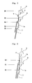
- the container as a whole is of the shape of a cup, has a body wall 1 and a bottom wall 2 closing the lower end of the body wall 1, the upper end of the body wall 1 being opened to form a mouth portion which is forming a flange 3 at an upper end of the body wall 1. That is, after the content such as a food or a beverage is contained in the container, the flange 3 is heat-sealed with a sealing foil (not shown) such as an aluminum foil, and the container is put to the vending.
- the bottom wall 2 may be formed flat as a whole. As shown in Fig.
- the bottom wall 2 is recessed to some extent from the lower end of the body wall 1 from the standpoint of stability when the container is placed and resistance against the deformation. Further, the container as a whole is transparent but the flange 3 is often opaque.
- a thick portion 2a which is the remaining portion of gate stemming from the injection gate is formed at the center of the bottom wall 2.
- the thickness of the thick portion 2a is relatively greater than other portions of the bottom wall 2 and, usually, protrudes to a height t of about 0.1 to about 3.0 mm though it may vary depending upon the size of the container, use and stretching ratio at the time of stretch-forming that will be described later.
- the thick portion 2a is formed when a preform that will be described later is formed by injection forming.
- the present invention has a feature in that the bottom wall 2 except the thick portion 2a therein, the body wall 1 and, as required, the flange 3 are oriented and crystallized, and are, further, heat-set, but the thick portion 2a present at the center of the bottom wall 2 remains substantially amorphous.
- the fact that the thick portion 2a at the center of the bottom wall 2 remains amorphous means that this portion has not been substantially stretched, has not been oriented or crystallized and, besides, has not been heat-set.
- the thick portion 2a of the container of the invention has a crystallinity of smaller than 15% and, desirably, as very small as not larger than 5% as measured by the densitometry, and is substantially amorphous while other portions are oriented and crystallized.
- the bottom wall 2 except the thick portion 2a has a crystallinity of not smaller than 15% and, particularly, the body wall 1 has a crystallinity of not smaller than 35%.
- the thick portion 2a which remains substantially amorphous exhibits flexibility or elasticity specific to the amorphousness, providing a function for improving the shock resistance.
- the container of the invention exhibits excellent heat resistance and excellent shock resistance despite of having the thick portion 2a that stems from the remaining portion of the injection gate.
- the container of the invention (Example 1) having the amorphous thick portion 2a exhibits very excellent heat resistance and shock resistance yet maintaining transparency in the thick portion 2a.
- the container (Comparative Example 1) having the thick portion 2a that is heat-fixed on the other hand, spherulites are formed in the thick portion 2a.
- the shock resistance decreases conspicuously and, besides, the thick portion 2a is opaque.
- the thermoplastic polyester resin that constitutes the above container is, particularly, a polyester resin that exhibits excellent transparency and shock resistance due to stretching and that can be effectively heat-set.
- a polyethylene terephthalate, a polypropylene terephthalate and a polyester comprising polylactic acid as a chief constituent component, that have glass transition points of not lower than room temperature and crystallinity Particularly, it is desired to use a polyethylene terephthalate having ethylene terephthalate units of not less than 80 mol% and, particularly, not less than 90 mol% from the standpoint of economy, formability and properties of the formed body.
- the copolymerizable components when the above polyethylene terephthalate is used are, desirably, isophthalic acid, 2,6-naphthalenedicarboxylic acid, 1,4-butanediol and 1,4-cyclohexanedimethanol.
- isophthalic acid 2,6-naphthalenedicarboxylic acid
- 1,4-butanediol 1,4-cyclohexanedimethanol
- the thermoplastic polyester resin the polyethylene terephthalate is most desired.
- polyethylene/butylene terephthalate polyethylene terephthalate/2,6-naphthalate, polyethylene terephthalate/isophthalate, or a blend thereof with polybutylene terephthalate, polybutylene terephthalate/isophthalate, polyethylene-2,6-naphthalate, polybutylene terephthalate/adipate, polyethylene-2,6-naphthalate/isophthalate, or polybutylene terephthalate/adipate or two or more kinds thereof.
- the polyester has an intrinsic viscosity [IV] of not smaller than 0.5 and, particularly, in a range of 0.6 to 1.5 as measured by using, as a solvent, a phenol/tetrachloroethane mixed solvent from the standpoint of formability of a preform, formability of a container, and mechanical properties and heat resistance of the container.
- the polyester may be blended with at least one of ethylene polymer, thermoplastic elastomer, polyacrylate or polycarbonate as a reforming resin component. It is desired that the reforming resin component is, usually, used in an amount of up to 60 parts by weight and, particularly preferably, in an amount of 3 to 20 parts by weight per 100 parts by weight of the polyester.
- thermoplastic polyester resin that constitutes the above container may be blended with known blending agents, such as antioxidant, heat stabilizer, ultraviolet ray absorber, antistatic agent, filler, lubricant and inorganic or organic coloring agent.
- known blending agents such as antioxidant, heat stabilizer, ultraviolet ray absorber, antistatic agent, filler, lubricant and inorganic or organic coloring agent.
- the cup-shaped containers shown in Fig. 1 are preserved or transported in a state of being stacked one upon the other.
- the containers of the upper sides deeply fit into the containers of the lower sides due to their own weights and it becomes difficult to separate the stacked containers from each other.
- the body wall 1 of the container is formed in a shape as shown in Fig. 2 .
- the upper end portion 4 (portion continuous to the flange 3) of the body wall 1 is a point from where the stretching starts and is formed relatively thick due to such a reason that the flange 3 (particularly, the back surface of the flange 3) has been heat-crystallized.
- a bead portion 5 is formed under the thick portion 4 and, further, an annular stepped portion 7 (hereinafter often referred to as stack portion) is formed protruding inward under the bead portion 5.
- stack portion annular stepped portion 7
- the outer surface of the stack portion 7 of an upper container A comes in contact with the upper surface of the bead portion 5 of a lower container B to maintain the stacked state. This makes it possible to effectively alleviate such an inconvenience that the upper container A falls deeply into the lower container B, i.e., to effectively alleviate such an inconvenience it becomes difficult to separate the upper container A and the lower container B from each other.
- the overlapping width d can be increased making it possible to stack the containers maintaining stability.
- limitation is imposed on the inner diameter of the flange 3 (container mouth portion) or on the shape of the body wall 1a near the flange 3. Therefore, stabilization in the stacking by the formation of the bead portion 5 is very meaningful. It is, for instance, desired that the overlapping width d of the upper container A and the lower container B is set to be not smaller than 0.5 mm and, particularly, not smaller than 0.8 mm.
- the bead portion 5 is so formed that a difference (D3 - D4) between the inner diameter D3 of the body wall 1a and the inner diameter D4 of the bead portion 5 is not smaller than 1.0 mm.
- the inner diameter D5 of the stack portion 7 should be set to be smaller than the inner diameter D4 of the bead portion 5 so that the outer surface of the stack portion (annular stepped portion) 7 of the upper container A is stably held by the upper surface of the bead portion 5.
- the bead portion 5 may be so formed that the container is stacked without being tilted. Namely, the bead portion 5 may be formed like a ring over the whole circumference of the body wall 1, or a plurality of pad portions 5 may be locally and symmetrically formed on the body wall 1.
- the containers can be stacked one upon the other maintaining stability.
- the bead portion 5 works as a reinforcing rib to improve the mechanical strength of the body wall 1.
- the polyester container of the present invention is produced by heating a preform of the shape of a sheet and of nearly a disk formed by injection-forming the above thermoplastic polyester resin at a predetermined heat-forming temperature and effecting the stretch-forming through steps shown in Figs. 5(a) to 5(e) .
- the preform (designated at 10 in Fig. 5 ) is obtained in substantially an amorphous state, and the central portion thereof (designated at 10a in Fig. 5 ) is formed thick being corresponded to the center of the bottom wall 2. Namely, the thick portion is the remaining portion of the injection gate corresponding to the injection gate of the injection-forming machine.
- the temperature for heating the preform 10 at the time of stretch-forming is not lower than a glass transition temperature (Tg) of the thermoplastic polyester resin that constitutes the preform but is lower than a crystallization starting temperature (Tic) thereof. If the heating temperature is lower than the glass transition temperature (Tg), an excess of force is needed for the heat-forming at steps that will be described below. If the heating temperature is not lower than the crystallization starting temperature (Tic), on the other hand, spherulites are formed and the transparency tends to be impaired.
- Tg glass transition temperature
- Tic crystallization starting temperature
- the glass transition temperature (Tg) and the crystallization starting temperature (Tic) used in the specification are found from a DSC curve that is obtained by picking up about 10 mg of the formed body that is to be measured, holding the sample at 300°C for 3 minutes in a nitrogen gas atmosphere, quickly cooling the sample down to room temperature, and elevating the temperature at a heating rate of 20°C a minute by using a differential scanning calorimeter (DSC).
- DSC differential scanning calorimeter
- the preform 10 heated at the above temperature is tightened on a forming metal mold (female metal mold) 14 by using an annular tightening member 12.
- a stretching rod 16 is extending through the annular tightening member 12, a communication hole is formed in the central portion of the forming metal mold 14, and a cooling rod 18 is extending through the communication hole. These rods are allowed to move up and down and, particularly, the cooling rod 18 moves following the stretching rod 16.
- the end surface of the cooling rod 18 is, usually, of nearly a size capable of coming in contact with the whole thick portion formed at the central portion 10a of the preform 10 while the end surface of the stretching rod 16 is larger than the end surface of the cooling rod 18.
- the stretching rod 16 and the cooling rod 18 have gas flow passages formed therein in the axial direction thereof.
- the circumferential edge portion 11 (corresponding to the flange 3 of the container of Fig. 1 ) of the preform 10 is preheated and is heat-crystallized to impart heat resistance thereto.
- the step of heat-crystallization will be described later.
- the circumferential edge portion 11 of the preform 10 is held by the forming metal mold 14 and by the annular tightening member 12.
- the tightening pressure is desirably increased to pressurize with a pressure of about 4.5 to about 13 MPa.
- the circumferential edge portion 11 that is heated at higher than the glass transition temperature is stretched and its thickness decreases down to, for example, about one-third to one-half. Therefore, the circumferential edge portion 11 is oriented and crystallized by the flow of resin and heat resistance is imparted thereto.
- a suitable lubricant such as silicone oil to the upper surface and lower surface of the circumferential edge portion 11 of the preform 10, or to the lower surface of the annular tightening member 12 or to the upper surface of the forming metal mold 14.
- Stretching is effected as shown in Fig. 5(b) following the step of tightening the mold for the preform 10. That is, in the step of stretching, the stretching rod 16 is stretched, the central portion of the preform 10 (corresponding to the thick portion 2a at the center of bottom of the container of Fig. 1 ) is held between the stretching rod 16 and the cooling rod 18, to thereby effect the stretching in the axial direction by using the stretching rod 16 and the blow-stretching.
- the stretching is effected in the axial direction by stretching the stretching rod 16 in the axial direction.
- the cooling rod 18 moves following the stretching rod 16 that stretches. That is, no excess of pressure acts on the portion (central portion 10a of the preform 10) held by the rods 16 and 18. Besides, this portion is cooled by the cooling rod 18. Accordingly, fluidization of the resin is effectively suppressed in this portion.
- the orientation and crystallization are suppressed at the central portion 10a of the preform 10, i.e., at the portion corresponding to the thick portion 2a at the center of bottom of the container. Therefore, the amorphous state is maintained at the portion corresponding to the thick portion 2a at the center of bottom of the container.
- the cooling rod 18 retreats to a position recessed from the cavity surface 14a of the forming metal mold 14 by the thickness of the thick portion. Thereafter, the compressed air or the like is blown out from the gas flow passage formed in the stretching rod 16 to effect the blow-stretching. Therefore, the preform 10 is formed in the shape of the cavity surface 14a of the forming metal mold 14 while leaving the thick portion at the central portion 10a of the preform 10.
- the portions other than the central portion 10a are oriented and crystallized to enhance the heat resistance.
- the stretch-formed body 20 obtained above is heat-set.
- the heat-setting is effected by bringing the stretch-formed body 20 into contact with the cavity surface 14a of the forming metal mold 14 that is heated to the heat-setting temperature in order to accelerate the crystallization while relaxing the distortion caused by forming. This further contributes to improve the heat resistance and the mechanical strength.
- the heat-setting temperature is higher than a crystallization initiating temperature (Tic) of the thermoplastic polyester forming the preform 10 (stretch-formed body 20) but is lower than a melting point (Tm) thereof and, particularly, is not higher than the melting point (Tm) - 10°C (usually, about 180°C).
- the heat-setting temperature is not lower than the melting point (Tm), it is probable that the stretch-formed body 20 melt-adheres to the forming metal mold 14. If the heat-setting temperature is lower than the crystallization initiating temperature (Tic), the crystallization is not sufficient, distortion due to forming is not sufficiently relaxed, and heat resistance and strength are not obtained. Further, the heat-fixing time is, usually, about 0.5 to about 5 seconds though it may vary depending upon the level of heat resistance that is desired.
- the central portion 20a of the stretch-formed body 20 (corresponds to the central portion 10a of the preform 10) is not in contact with the forming metal mold 14 but is in contact with the cooling rod 18 and is cooled. Therefore, no heat-setting is effected for the thickly formed central portion 20a that is the remaining portion of the injection gate. As a result, the central portion 20a is maintained in the amorphous state but other portions (e.g., bottom portion excluding the central portion 20a, body portion and flange) are heat-fixed. That is, if the thickly formed central portion 20a is heated at the heat-setting temperature, spherulites form causing a decrease in the shock resistance and impairing the transparency. By maintaining the thick central portion 20a amorphous, however, the transparency is maintained, and flexibility and elasticity are imparted owing to the amorphous property effectively alleviating a decrease in the shock resistance.
- the forming metal mold 14 can be easily heated to the heat-fixing temperature by providing heating means such as a heater in the forming metal mold 14.
- the above heating may be effected after the stretch-forming.
- the forming metal mold 14 is heated at the heat-setting temperature in advance and, in this state, the above step of tightening and the step of stretching are conducted, and the heating is discontinued after the heat-setting has been finished.
- the cooling rod 18 is cooled by a suitable coolant and its temperature is so set that at least the central portion 20a of the stretch-formed body 20 is lower than the heat-setting temperature (particularly, lower than the glass transition temperature in the step of stretching).
- the heat-setting temperature particularly, lower than the glass transition temperature in the step of stretching.
- the central portion of the stretch-formed body 20 or of the preform 10 is not elevated to be higher than the heat-setting temperature or the glass transition temperature by the radiation of heat.
- a cooling core metal mold 22 is inserted through an annular space of the annular tightening member 12 [ Fig. 5(d) ].
- the shape of outer surface of the cooling core metal mold 22 corresponds to the shape of the container shown in Fig. 1 .
- a recessed portion forming the bead portion and a stepped surface are formed in the outer surface of the cooling core metal mold 22 at corresponding positions.
- a compressed gas such as the compressed air is blown from the gas flow passage of the cooling rod 18.
- the gas is sucked under a reduced pressure through the gas flow passage of the stretching rod 16 to effect the shrink back [ Fig. 5(e) ]. Due to the shrink back, the stretch-formed body 20 is formed in the shape of the final container and is quickly cooled. By taking out the stretch-formed body 20, a container having the final shape is obtained as shown in Fig. 1 or 2 .
- the above-mentioned method makes it possible to obtain the container as shown in Fig. 1 or 2 .
- the thick portion 2a formed at the central portion of the bottom portion 2 is substantially amorphous while other portions are oriented, crystallized and are heat-fixed.
- the thick portion 2a at the center of the bottom wall 2 is not oriented, crystallized or heat-set. Therefore, excellent heat resistance and shock resistance are exhibited.
- the preform 10 formed by injection-forming is heat-crystallized for its circumferential edge portion 11 (corresponds to the flange 3) to enhance its heat resistance prior to effecting the forming through the above step.
- the circumferential edge portion (hereinafter called flange) 11 is wholly heat-crystallized, however, it becomes difficult to effect the heat-sealing. Therefore, the back surface of the flange 11 is selectively heat-crystallized by being selectively heated to maintain, in the amorphous state, the surface of the flange 11 to which various lid members will be fixed by heat-sealing.
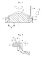
- the selective heat-crystallization is conducted by holding the preform 10 upside down on a cooling jig 30 as shown in Fig. 6.
- Fig. 6 and the succeeding drawings do not show the thick portion 20a of the preform 10 that stems from the remaining portion of the gate formed by the injection-forming.
- the cooling jig 30 has a ring-like support fitting 30a and a core-support fitting 30b which are formed by using a metal material such as a stainless steel, aluminum or a steel, and are, as required, so constituted that a coolant such as cooling water or the like circulates therein. Or, the jig 30 has heat-radiating fins formed thereon. Besides, the ring-like support fitting 30a and the core support fitting 30b are integrally coupled together so as to rotate together. The ring-like support fitting 30a is supporting the surface 11a of flange 11 of the preform 10 and the core support fitting 30b is supporting the inner surface of the stretch-formed portion of the preform 10.
- the stretch-formed portion is a central portion of the preform 10 surrounded by the flange 11, and is the portion that is stretch-formed as described above. That is, in conducting the heat-treatment as described below, the surface 11a of flange 11 of the preform 10 and the stretch-formed portion are effectively suppressed by these members 30a and 30b from being heated at temperatures higher than the heat-crystallization temperature.
- a heat source 33 is provided on the side of the back surface 11b of flange 11 of the preform 10 to selectively heat the back surface 11b of flange 11, to improve the strength and heat resistance of the flange 11 by the heat-crystallization, and to maintain the surface 11a of flange 11 in the amorphous state. Further, the stretch-formed portion of the preform 10 is prevented from being heat-crystallized, so that no inconvenience occurs in the stretch-forming that is caused by an increase in the softening point or the like.
- the heat-crystallization is effectively executed by the selective heating since the preform 10 is held upside down.
- the heating is effected from the side of the back surface 11b of flance 11 by holding the preform 10 upright, the flange 11 is softened by heating and a gap forms between the surface 11a of the flange 11 and the ring-like support fitting 30a for cooling. Therefore, the surface 11a of the flange is not effectively cooled and this portion, too, is heat-crystallized (if the surface 11a of the flange is heat-crystallized, it becomes difficult to fix the lid member or the like thereto by heat-sealing).
- the heat source 33 there can be used a carbonic acid gas laser, a near infrared-ray heater, a far infrared-ray heater, or a hot air heater.
- the heating is effected by the heat source 33 of which the position has been fixed while rotating the cooling jig 30.
- the carbonic acid gas laser is used, the portion irradiated with laser can be easily adjusted offering an advantage of selectively heating the back surface 11b of the flange 11.
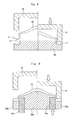
- other means is used as the heat source 33, it is not easy to adjust the heated portion. As shown, for example, in Fig.
- the shielding member 35 is formed by using a metal having high heat conductivity. Provision of the shielding member 35 effectively prevents the stretch-formed portion of the preform 10 from being heated, and enables the back surface 11b of the flange 11 to be efficiently and selectively heated.
- the core support fitting 30b for cooling is intimately adhered onto the whole inner surface of the stretch-formed portion of the preform 10 and offers advantages of reducing the load exerted on the surface 11a of the flange and effectively preventing the flange 11 from being deformed by heating.
- the whole inner surface of the stretch-formed portion of the preform 10 does not have to be closely contacted to the core support fitting 30b unless the stretch-formed portion is heated to be higher than the heat-crystallization temperature.
- a suitable space may be formed between the central portion 20a of the stretch-formed portion and the core support fitting 30b.
- the surface 11a of the flange of the preform 10 In order to reliably maintain amorphous the surface 11a of the flange in the above step of selective heat-crystallization, it is desired to provide the surface 11a of flange of the preform 10 with an annular protuberance 37 as shown in Fig. 7 .
- the annular protuberance 37 has a substantially flat surface 37a at the upper end. If the selective heat-crystallization is effected by providing the above annular protuberance 37, it is allowed to reliably suppress the heat-crystallization in the flat surface 37a of the annular protuberance 37 and the lid member can be easily fixed to the above portion by heat-sealing.
- the height h of the annular protuberance 37 is about 0.1 to about 2 mm. From the standpoint of maintaining a sufficient width of heat-sealing, it is desired that the width w of flat surface 37a of the annular protuberance 37 is about 0.5 to about 3.0 mm.
- the flange 11 forming the annular protuberance 37 is to be selectively heat-crystallized, it is desired that the flat surface 37a only of the annular protuberance 37a is brought into contact with the annular support fitting 30a for cooling but other portions of the flange surface 11a are floating a from the standpoint of conducting the efficient cooling.
- the flange 11 is held from the back surface thereof by a cooling upper mold 41 while slightly broadening the mouth diameter of the flange 11 by using a cooling lower mold 39 as shown in Fig. 8 after the above selective heating while the flange 11 is still in a softened state, and the flange 11 is tightened with a suitable pressure and is cooled and fixed to a suitable size. As shown in Fig.
- annular cooling lower mold 30c for limiting the mouth diameter is provided so as to slide between the annular support fitting 30a and the core support fitting 30b. Therefore, the annular support fitting 30a for cooling can be utilized as the cooling lower mold 39 that is shown in Fig. 8 .
- the annular cooling lower mold 30c for limiting the mouth diameter is elevated and is inserted in the mouth of the flange 11 and, at the same time, the cooling upper mold 41 is lowered to tighten the flange 11 relative to the annular support fitting 30a.
- the preform 10 with the back surface 11b of the flange 11 being selectively heat-crystallized and with the surface 11a of the flange 11 being maintained amorphous, is subjected to the above step of stretch-forming and is formed into a container.
- Crystallinity ⁇ ⁇ c ⁇ ⁇ c x ⁇ - ⁇ ⁇ a / ⁇ x ⁇ c - ⁇ a x 100
- the density was measured by using an n-heptane-carbon tetrachloride type density-gradient tube (manufactured by Ikeda Rika Co.) under a condition of 20°C.
- the containers were each filled with 200 ml of water and were sealed. Thereafter, the containers were fallen from a height of 80 cm with their bottoms facing downward. The containers were repetitively fallen 5 times. Thereafter, the bottom portions were checked for their deformation by eyes and were evaluated to be ⁇ when there was no crack.
- the centers of the bottom portions were measured for their transparency (haze) by using a hazeometer manufactured by Suga Shikenki Co.
- the centers of the bottoms were evaluated to be ⁇ when the haze was not higher than 10%.
- a polyethylene terephthalate resin having an intrinsic viscosity of 0.8 dl/g (SA135 manufactured by Mitsui Kagaku Co., containing 2 mol% of isophthalic acid) was fed to an injection-forming machine (NN75JS manufactured by Niigata Tekkojo Co.), and was injection-formed under the conditions of an injection temperature of 275 to 300°C and an injection pressure of 10 Kg/cm 2 to obtain 15.6 g of a substantially amorphous preform of a single layer.
- the flange portion of the preform was heated up to 180°C and was heat-crystallized by the irradiation by using a near infrared-ray heater.
- the preform was heated at 95°C which was higher than the glass transition temperature thereof, and was formed according to a process of Figs. 5 (a) to 5 (e) to obtain a cup-like container with a flange.
- the forming metal mold was maintained at a temperature of 180°C while the cooling rod and the cooling core metal mold were maintained at 30°C.
- Table 1 shows the sizes of the tools, measured results of the crystallinity and evaluated results of the properties.
- the central portion of the bottom portion was amorphous and the bottom portion surrounding the central portion was oriented and crystallized exhibiting sufficiently practicable properties concerning both heat resistance and shock resistance.
- a cup-like container with a flange was obtained under the same conditions as those of Example but without using the cooling rod in the process of Figs. 5(a) to 5(e) .
- Table 1 shows the sizes of the tools, measured results of the crystallinity and evaluated results of the properties.
Description
- The present invention relates to a polyester container and a method of its production. More particularly, the invention relates to a thermoplastic resin container having excellent heat resistance and shock resistance obtained by stretch-forming a preform that is formed by injection forming, and to a method of its production.
- As is well known, polyester containers as represented by polyethylene terephthalate (PET) containers have been used in a variety of applications and, most, widely, for foods and beverages. Further, cup-like containers having a wide mouth and a flange along the circumferential edge of the mouth have been placed in practical use as thermoplastic resin containers for foods and beverages.
- As a method of producing the cup-like containers, a
patent document 1 teaches a method of producing a cup-like container by forming a sheet-like preform by injection forming and by subjecting the preform to the heat forming such as plug-assisted forming. Patent documentUS2002/0150703 A1 discloses a method of making a polyester container having an enhanced level of crystallinity in the sidewall while maintaining a low level of crystallinity in a thickened base portion. The container is refillable and can withstand higher caustic wash temperatures and exhibits reduced flavour carryover and can be used as a hot-fill container. - According to the above methods of forming the preform by injection forming and heat-forming the preform, a problem remains in that a central portion of the bottom of the container is formed thick due to the remaining portion of the injection gate, and breakage easily occurs due to the thick portion. Patent document
US 5 648 133 A discloses a resin container having a bottom structure which has a central recessed portion containing substantially no crystal, a marginal raised portion crystallised by molecular orientation, and an intermediate ring-shaped portion crystallised to have spherulite-like crystals. The bottom structure highly improves the heat-resistance at the intermediate portion, while maintaining the central recessed portion at a good impact-resistance. Apatent document 2 proposes a production method which avoids the formation of a thick portion. Concretely speaking, thepatent document 2 teaches a plug-assisted forming method in which a portion corresponding to the center of the bottom of the preform of which the peripheral edge is fixed is held between a preforming plug and a bottom-holding plug, and the preforming plug is extruded in this state to form the preform. - Patent document 1:
JP-A-5-69478 - Patent document 2:
JP-A-6-134850 - Patent document
JP 10 071641A - Patent Document
JP 62 187012 A - According to the method of the
patent document 1, however, the obtained container has a problem of poor heat resistance in addition to the formation of the thick portion. According to the method of thepatent document 2, too, the obtained container has poor heat resistance. Besides, to remove the thick portion, the center of bottom of the preform must be held between the preforming plug and the bottom-holding plug with a very large pressure to push and crush the thick portion arousing a problem in that the apparatus is placed under severe conditions such as exerting a large load on the apparatus. - The applicant has previously proposed a method of producing a cup-like container by blow-forming and stretching the preform followed by heat-setting by heating, shrinking the preform back to impart the shape of a final container, and cooling the container (
JP-A-2004-291621 - It is therefore an object of the present invention to provide a polyester container having excellent heat resistance and shock resistance and a method of its production.
- Another object of the present invention is to provide a polyester container having excellent heat resistance and shock resistance despite the center of the bottom is formed thick, that is a portion remaining in the injection gate and a method of its production.
- According to a first aspect the present invention, there is provided a polyester container (A) obtained by stretch-forming a preform of a thermoplastic polyester resin formed by injection forming characterised in that:
- a central portion of a bottom wall is the remaining part of the gate at the time of injection forming, and is formed relatively thicker than a bottom wall portion surrounding the central portion;
- the central portion of the bottom wall is substantially amorphous, and the bottom wall portion surrounding the central portion is oriented and crystallized;
- the bottom wall other than the central portion has a crystallinity of not smaller than 15%; and
- the crystallinity is not less than 15% at a position 10mm away from the centre of the bottom.
- In the polyester container of the present invention, it is desired that:
- (1) a bead portion protruding inward and a stepped portion are formed in an upper portion of the body wall, the stepped portion being positioned under the bead portion and protruding inward.
According to a second aspect the present invention, there is provided a method of producing a polyester container according to the first aspect of the present invention, comprising:- forming a preform of a thermoplastic polyester resin by injection forming;
- holding the remaining portion of the injection gate of the preform between a stretching rod and a cooling rod;
- drawing in the axial direction by stretching the stretching rod and causing the cooling rod to move following the stretching rod and, further, blow-drawing by blowing a fluid;
- characterised by bringing an outer surface of the stretch-formed body into contact with a surface of a heating metal mold that is maintained heated by blow-drawing except the portion to where the cooling rod is contacting, in order to form the formed body into the shape of a container; and
- heat-setting by heating by the contact with the surface of the heating metal mold except a portion to where the cooling rod is contacting. In the above production method, it is desired that:
- (1a) after the heat-setting, a cooling core metal mold is inserted in the stretch-formed body formed in the shape of a container, and the stretch-formed body is shrunk back to the shape of the core metal mold, followed by cooling.
- (2) the back surface of the flange formed on the preform is selectively heat-crystallized prior to holding the remaining portion of the injection gate of the preform between the stretching rod and the cooling rod;
- (3) the preform is positioned upside down, and the back surface side of the flange is selectively heated so as to be heat-crystallized by holding the front surface side of the flange by using a cooling jig;
- (4) the cooling jig has a ring-like support fitting and a core-support fitting positioned in the ring, the front surface side of the flange is held by the ring-like support fitting at the time of selectively heating the back surface side of the flange, and the inner surface of the stretch-formed portion of the preform surrounded by the flange is held by the core-support fitting;
- (5) on the back surface side of the preform, a shielding plate that suppresses the conduction of heat is arranged near the boundary portion between the flange and the stretch-formed portion to selectively heat the back surface side of the flange;
- (6) after the back surface side of the flange is selectively heated, the flange is clamped to stabilize the size of the flange; and
- (7) a recessed portion and a stepped surface corresponding to the bead portion and to the annular stepped portion formed in the body wall of the container, are formed in the outer surface of the cooling core metal mold.
- In the polyester container of the present invention, the center of bottom portion of the container that is the remaining portion of the injection gate is substantially amorphous while other portions are oriented and crystallized. Owing to the amorphous center of the bottom portion, flexibility is exhibited making it possible to enhance the shock resistance yet maintaining excellent heat resistance. That is, the polyester container of the present invention exhibits excellent heat resistance as well as excellent shock resistance despite it has the thick portion that is the remaining portion of the injection gate at the center of the bottom.
- According to the method of producing the polyester container of the present invention, the stretch-forming (drawing in the axial direction and blow-drawing) is effected while holding the remaining portion of the injection gate (thick portion) of the preform between the stretching rod and the cooling rod. Here, the thick portion is not removed but is left and is rendered to be amorphous. Therefore, the thick portion does not have to be held by the above rods with a high pressure; i.e., the cooling rod moves following the stretching rod that stretches effectively alleviating such an inconvenience that a large load is exerted on the apparatus. Further, only the portion that becomes the center of the bottom portion with which the cooling rod is in contact is cooled by utilizing the cooling rod while other portions are heat-set by using the heated metal mold. Therefore, other portions are oriented and crystallized to improve the heat resistance while maintaining the center of the bottom portion of the container amorphous.
-
-
Fig. 1 is a side sectional view showing a representative shape of a polyester container of the present invention; -
Fig. 2 is a side sectional view illustrating, on an enlarged scale, a portion of the shape of a body wall where a bead portion is formed in the polyester container of the present invention; -
Fig. 3 is a side sectional view illustrating, on an enlarged scale, a portion of the state where the polyester containers having the body wall ofFig. 2 are stacked; -
Fig. 4 is a side sectional view illustrating, on an enlarged scale, a portion of the state where the polyester containers having the body wall without bead portion are stacked; -
Fig. 5 is a view of steps illustrating a process for producing the container ofFig. 1 ; -
Fig. 6 is a view illustrating a step of selectively heat-crystallizing a flange of a preform; -
Fig. 7 is a view illustrating a preferred shape of the flange of the preform; -
Fig. 8 is a view illustrating means for stabilizing the size of the flange conducted for the preform after the heating for the selective heat-crystallization ofFig. 6 ; and -
Fig. 9 is a view illustrating means for stabilizing the size different from that of Fig. S. - A polyester container of the present invention and a method of its production will now be described in detail with reference to the accompanying drawings.
- Referring to
Fig. 1 showing a representative shape of the polyester container of the invention, the container as a whole is of the shape of a cup, has abody wall 1 and abottom wall 2 closing the lower end of thebody wall 1, the upper end of thebody wall 1 being opened to form a mouth portion which is forming aflange 3 at an upper end of thebody wall 1. That is, after the content such as a food or a beverage is contained in the container, theflange 3 is heat-sealed with a sealing foil (not shown) such as an aluminum foil, and the container is put to the vending. Thebottom wall 2 may be formed flat as a whole. As shown inFig. 1 , however, it is desired that thebottom wall 2 is recessed to some extent from the lower end of thebody wall 1 from the standpoint of stability when the container is placed and resistance against the deformation. Further, the container as a whole is transparent but theflange 3 is often opaque. - In the container of the invention as will be understood from
Fig. 1 , athick portion 2a which is the remaining portion of gate stemming from the injection gate is formed at the center of thebottom wall 2. The thickness of thethick portion 2a is relatively greater than other portions of thebottom wall 2 and, usually, protrudes to a height t of about 0.1 to about 3.0 mm though it may vary depending upon the size of the container, use and stretching ratio at the time of stretch-forming that will be described later. Thethick portion 2a is formed when a preform that will be described later is formed by injection forming. - The present invention has a feature in that the
bottom wall 2 except thethick portion 2a therein, thebody wall 1 and, as required, theflange 3 are oriented and crystallized, and are, further, heat-set, but thethick portion 2a present at the center of thebottom wall 2 remains substantially amorphous. The fact that thethick portion 2a at the center of thebottom wall 2 remains amorphous means that this portion has not been substantially stretched, has not been oriented or crystallized and, besides, has not been heat-set. That is, thethick portion 2a of the container of the invention has a crystallinity of smaller than 15% and, desirably, as very small as not larger than 5% as measured by the densitometry, and is substantially amorphous while other portions are oriented and crystallized. Thebottom wall 2 except thethick portion 2a has a crystallinity of not smaller than 15% and, particularly, thebody wall 1 has a crystallinity of not smaller than 35%. Thus, thethick portion 2a which remains substantially amorphous exhibits flexibility or elasticity specific to the amorphousness, providing a function for improving the shock resistance. As a result, the container of the invention exhibits excellent heat resistance and excellent shock resistance despite of having thethick portion 2a that stems from the remaining portion of the injection gate. - For instance, as will be obvious from the experimental results of Example and Comparative Example described later, the container of the invention (Example 1) having the amorphous
thick portion 2a exhibits very excellent heat resistance and shock resistance yet maintaining transparency in thethick portion 2a. In the container (Comparative Example 1) having thethick portion 2a that is heat-fixed, on the other hand, spherulites are formed in thethick portion 2a. As a result, though the heat resistance is favorable, the shock resistance decreases conspicuously and, besides, thethick portion 2a is opaque. - In the present invention, the thermoplastic polyester resin that constitutes the above container is, particularly, a polyester resin that exhibits excellent transparency and shock resistance due to stretching and that can be effectively heat-set. Particularly preferably, there can be used a polyethylene terephthalate, a polypropylene terephthalate and a polyester comprising polylactic acid as a chief constituent component, that have glass transition points of not lower than room temperature and crystallinity. Particularly, it is desired to use a polyethylene terephthalate having ethylene terephthalate units of not less than 80 mol% and, particularly, not less than 90 mol% from the standpoint of economy, formability and properties of the formed body. The copolymerizable components when the above polyethylene terephthalate is used are, desirably, isophthalic acid, 2,6-naphthalenedicarboxylic acid, 1,4-butanediol and 1,4-cyclohexanedimethanol. As the thermoplastic polyester resin, the polyethylene terephthalate is most desired. Not being limited thereto only, there can be used polyethylene/butylene terephthalate, polyethylene terephthalate/2,6-naphthalate, polyethylene terephthalate/isophthalate, or a blend thereof with polybutylene terephthalate, polybutylene terephthalate/isophthalate, polyethylene-2,6-naphthalate, polybutylene terephthalate/adipate, polyethylene-2,6-naphthalate/isophthalate, or polybutylene terephthalate/adipate or two or more kinds thereof. It is desired that the polyester has an intrinsic viscosity [IV] of not smaller than 0.5 and, particularly, in a range of 0.6 to 1.5 as measured by using, as a solvent, a phenol/tetrachloroethane mixed solvent from the standpoint of formability of a preform, formability of a container, and mechanical properties and heat resistance of the container. The polyester may be blended with at least one of ethylene polymer, thermoplastic elastomer, polyacrylate or polycarbonate as a reforming resin component. It is desired that the reforming resin component is, usually, used in an amount of up to 60 parts by weight and, particularly preferably, in an amount of 3 to 20 parts by weight per 100 parts by weight of the polyester.
- The thermoplastic polyester resin that constitutes the above container may be blended with known blending agents, such as antioxidant, heat stabilizer, ultraviolet ray absorber, antistatic agent, filler, lubricant and inorganic or organic coloring agent.
- After produced, the cup-shaped containers shown in
Fig. 1 are preserved or transported in a state of being stacked one upon the other. When stacked, however, the containers of the upper sides deeply fit into the containers of the lower sides due to their own weights and it becomes difficult to separate the stacked containers from each other. To alleviate the above inconvenience, it is desired that thebody wall 1 of the container is formed in a shape as shown inFig. 2 . - In
Fig. 2 , the upper end portion 4 (portion continuous to the flange 3) of thebody wall 1 is a point from where the stretching starts and is formed relatively thick due to such a reason that the flange 3 (particularly, the back surface of the flange 3) has been heat-crystallized. Abead portion 5 is formed under thethick portion 4 and, further, an annular stepped portion 7 (hereinafter often referred to as stack portion) is formed protruding inward under thebead portion 5. Referring toFig. 3 , when the containers are stacked, the outer surface of thestack portion 7 of an upper container A comes in contact with the upper surface of thebead portion 5 of a lower container B to maintain the stacked state. This makes it possible to effectively alleviate such an inconvenience that the upper container A falls deeply into the lower container B, i.e., to effectively alleviate such an inconvenience it becomes difficult to separate the upper container A and the lower container B from each other. - If the
bead portion 5 is not formed as shown inFig. 4 , the outer surface of the body wall 1a over thestack portion 7 of the upper container A comes into engagement with the upper end (container opening) of the lower container B to maintain the stacked state. In this case, therefore, the overlapping width d of the upper container A and the lower container B is expressed by the following formula,
which is very small. That is, thebody wall 1 is usually formed being tilted from the upper end toward the inside. Therefore, the overlapping width d becomes a maximum when thebody wall 1 is vertically falling down, the maximum width dmax being,
which is merely equal to the thickness of the body wall 1a. When many containers are stacked one upon the other, therefore, the upper containers A deeply fall into the lower containers B due to their own weights making it difficult to separate them from each other. - When the
bead portion 5 is formed as shown inFig. 2 , on the other hand, the overlapping width d of the upper container A and the lower container B in the stacked state shown inFig. 3 is expressed by the following formula,
- By protruding the
bead portion 5 inward, therefore, the overlapping width d can be increased making it possible to stack the containers maintaining stability. In particular, when thecontainer body wall 1 is formed by shrink back that will be described later, limitation is imposed on the inner diameter of the flange 3 (container mouth portion) or on the shape of the body wall 1a near theflange 3. Therefore, stabilization in the stacking by the formation of thebead portion 5 is very meaningful. It is, for instance, desired that the overlapping width d of the upper container A and the lower container B is set to be not smaller than 0.5 mm and, particularly, not smaller than 0.8 mm. It is therefore desired that thebead portion 5 is so formed that a difference (D3 - D4) between the inner diameter D3 of the body wall 1a and the inner diameter D4 of thebead portion 5 is not smaller than 1.0 mm. Further, the inner diameter D5 of thestack portion 7 should be set to be smaller than the inner diameter D4 of thebead portion 5 so that the outer surface of the stack portion (annular stepped portion) 7 of the upper container A is stably held by the upper surface of thebead portion 5. - Here, the
bead portion 5 may be so formed that the container is stacked without being tilted. Namely, thebead portion 5 may be formed like a ring over the whole circumference of thebody wall 1, or a plurality ofpad portions 5 may be locally and symmetrically formed on thebody wall 1. - By forming the
bead portion 5 as described above, the containers can be stacked one upon the other maintaining stability. There is, further, an additional advantage in that thebead portion 5 works as a reinforcing rib to improve the mechanical strength of thebody wall 1. - The polyester container of the present invention is produced by heating a preform of the shape of a sheet and of nearly a disk formed by injection-forming the above thermoplastic polyester resin at a predetermined heat-forming temperature and effecting the stretch-forming through steps shown in
Figs. 5(a) to 5(e) . - The preform (designated at 10 in
Fig. 5 ) is obtained in substantially an amorphous state, and the central portion thereof (designated at 10a inFig. 5 ) is formed thick being corresponded to the center of thebottom wall 2. Namely, the thick portion is the remaining portion of the injection gate corresponding to the injection gate of the injection-forming machine. - It is desired that the temperature for heating the
preform 10 at the time of stretch-forming is not lower than a glass transition temperature (Tg) of the thermoplastic polyester resin that constitutes the preform but is lower than a crystallization starting temperature (Tic) thereof. If the heating temperature is lower than the glass transition temperature (Tg), an excess of force is needed for the heat-forming at steps that will be described below. If the heating temperature is not lower than the crystallization starting temperature (Tic), on the other hand, spherulites are formed and the transparency tends to be impaired. The glass transition temperature (Tg) and the crystallization starting temperature (Tic) used in the specification are found from a DSC curve that is obtained by picking up about 10 mg of the formed body that is to be measured, holding the sample at 300°C for 3 minutes in a nitrogen gas atmosphere, quickly cooling the sample down to room temperature, and elevating the temperature at a heating rate of 20°C a minute by using a differential scanning calorimeter (DSC). - Referring to
Fig. 5(a) , first, thepreform 10 heated at the above temperature is tightened on a forming metal mold (female metal mold) 14 by using anannular tightening member 12. - In
Fig. 5 (a) , thecircumferential edge portion 11 of thepreform 10 held by the annular tighteningmember 12 and the formingmetal mold 14 becomes a portion that corresponds to theflange 3 of the container. - A stretching
rod 16 is extending through the annular tighteningmember 12, a communication hole is formed in the central portion of the formingmetal mold 14, and a coolingrod 18 is extending through the communication hole. These rods are allowed to move up and down and, particularly, the coolingrod 18 moves following the stretchingrod 16. The end surface of the coolingrod 18 is, usually, of nearly a size capable of coming in contact with the whole thick portion formed at thecentral portion 10a of thepreform 10 while the end surface of the stretchingrod 16 is larger than the end surface of the coolingrod 18. - Though not shown, the stretching
rod 16 and the coolingrod 18 have gas flow passages formed therein in the axial direction thereof. - Prior to executing the above step, the circumferential edge portion 11 (corresponding to the
flange 3 of the container ofFig. 1 ) of thepreform 10 is preheated and is heat-crystallized to impart heat resistance thereto. The step of heat-crystallization will be described later. - Referring to
Fig. 5(a) , thecircumferential edge portion 11 of thepreform 10 is held by the formingmetal mold 14 and by the annular tighteningmember 12. When the heat-crystallization has not been effected, the tightening pressure is desirably increased to pressurize with a pressure of about 4.5 to about 13 MPa. When tightened with such a high pressure, thecircumferential edge portion 11 that is heated at higher than the glass transition temperature is stretched and its thickness decreases down to, for example, about one-third to one-half. Therefore, thecircumferential edge portion 11 is oriented and crystallized by the flow of resin and heat resistance is imparted thereto. - To accelerate the orientation and crystallization (fluidization of resin) by the pressurized tightening, it is desired to apply a suitable lubricant such as silicone oil to the upper surface and lower surface of the
circumferential edge portion 11 of thepreform 10, or to the lower surface of the annular tighteningmember 12 or to the upper surface of the formingmetal mold 14. - Stretching is effected as shown in
Fig. 5(b) following the step of tightening the mold for thepreform 10. That is, in the step of stretching, the stretchingrod 16 is stretched, the central portion of the preform 10 (corresponding to thethick portion 2a at the center of bottom of the container ofFig. 1 ) is held between the stretchingrod 16 and the coolingrod 18, to thereby effect the stretching in the axial direction by using the stretchingrod 16 and the blow-stretching. - In
Fig. 5(b) , the stretching is effected in the axial direction by stretching the stretchingrod 16 in the axial direction. Here, the coolingrod 18 moves following the stretchingrod 16 that stretches. That is, no excess of pressure acts on the portion (central portion 10a of the preform 10) held by therods rod 18. Accordingly, fluidization of the resin is effectively suppressed in this portion. As a result, the orientation and crystallization are suppressed at thecentral portion 10a of thepreform 10, i.e., at the portion corresponding to thethick portion 2a at the center of bottom of the container. Therefore, the amorphous state is maintained at the portion corresponding to thethick portion 2a at the center of bottom of the container. - After the stretching in the axial direction, the cooling
rod 18 retreats to a position recessed from thecavity surface 14a of the formingmetal mold 14 by the thickness of the thick portion. Thereafter, the compressed air or the like is blown out from the gas flow passage formed in the stretchingrod 16 to effect the blow-stretching. Therefore, thepreform 10 is formed in the shape of thecavity surface 14a of the formingmetal mold 14 while leaving the thick portion at thecentral portion 10a of thepreform 10. The portions other than thecentral portion 10a are oriented and crystallized to enhance the heat resistance. - Next, the stretch-formed
body 20 obtained above is heat-set. The heat-setting is effected by bringing the stretch-formedbody 20 into contact with thecavity surface 14a of the formingmetal mold 14 that is heated to the heat-setting temperature in order to accelerate the crystallization while relaxing the distortion caused by forming. This further contributes to improve the heat resistance and the mechanical strength. It is desired that the heat-setting temperature is higher than a crystallization initiating temperature (Tic) of the thermoplastic polyester forming the preform 10 (stretch-formed body 20) but is lower than a melting point (Tm) thereof and, particularly, is not higher than the melting point (Tm) - 10°C (usually, about 180°C). If the heat-setting temperature is not lower than the melting point (Tm), it is probable that the stretch-formedbody 20 melt-adheres to the formingmetal mold 14. If the heat-setting temperature is lower than the crystallization initiating temperature (Tic), the crystallization is not sufficient, distortion due to forming is not sufficiently relaxed, and heat resistance and strength are not obtained. Further, the heat-fixing time is, usually, about 0.5 to about 5 seconds though it may vary depending upon the level of heat resistance that is desired. - In effecting the heat-setting according to the present invention, the
central portion 20a of the stretch-formed body 20 (corresponds to thecentral portion 10a of the preform 10) is not in contact with the formingmetal mold 14 but is in contact with the coolingrod 18 and is cooled. Therefore, no heat-setting is effected for the thickly formedcentral portion 20a that is the remaining portion of the injection gate. As a result, thecentral portion 20a is maintained in the amorphous state but other portions (e.g., bottom portion excluding thecentral portion 20a, body portion and flange) are heat-fixed. That is, if the thickly formedcentral portion 20a is heated at the heat-setting temperature, spherulites form causing a decrease in the shock resistance and impairing the transparency. By maintaining the thickcentral portion 20a amorphous, however, the transparency is maintained, and flexibility and elasticity are imparted owing to the amorphous property effectively alleviating a decrease in the shock resistance. - In the present invention, the forming
metal mold 14 can be easily heated to the heat-fixing temperature by providing heating means such as a heater in the formingmetal mold 14. The above heating may be effected after the stretch-forming. Usually, however, the formingmetal mold 14 is heated at the heat-setting temperature in advance and, in this state, the above step of tightening and the step of stretching are conducted, and the heating is discontinued after the heat-setting has been finished. - The cooling
rod 18 is cooled by a suitable coolant and its temperature is so set that at least thecentral portion 20a of the stretch-formedbody 20 is lower than the heat-setting temperature (particularly, lower than the glass transition temperature in the step of stretching). Here, however, since the formingmetal mold 14 is heated, attention should be so given that the central portion of the stretch-formedbody 20 or of thepreform 10 is not elevated to be higher than the heat-setting temperature or the glass transition temperature by the radiation of heat. - In the present invention, after the above heat-setting, a cooling
core metal mold 22 is inserted through an annular space of the annular tightening member 12 [Fig. 5(d) ]. The shape of outer surface of the coolingcore metal mold 22 corresponds to the shape of the container shown inFig. 1 . Further, when thebead portion 5 and the stack portion 7 (annular stepped portion) are formed in the upper part of thebody wall 1 as shown inFig. 2 , a recessed portion forming the bead portion and a stepped surface are formed in the outer surface of the coolingcore metal mold 22 at corresponding positions. - After the
core metal mold 22 is inserted, a compressed gas such as the compressed air is blown from the gas flow passage of the coolingrod 18. As required, further, the gas is sucked under a reduced pressure through the gas flow passage of the stretchingrod 16 to effect the shrink back [Fig. 5(e) ]. Due to the shrink back, the stretch-formedbody 20 is formed in the shape of the final container and is quickly cooled. By taking out the stretch-formedbody 20, a container having the final shape is obtained as shown inFig. 1 or 2 . - It is also possible to obtain the stretch-formed
body 20 in the final shape of the container without conducting either the step of inserting the core or the step of shrink back. In this case, however, the cooling requires an extended period of time and the productivity very decreases. It is therefore desired to effect the step of inserting the core and the step of shrink back as described above in order to shorten the cooling time and to very increase the productivity. - Thus, the above-mentioned method makes it possible to obtain the container as shown in
Fig. 1 or 2 . In this container, thethick portion 2a formed at the central portion of thebottom portion 2 is substantially amorphous while other portions are oriented, crystallized and are heat-fixed. However, thethick portion 2a at the center of thebottom wall 2 is not oriented, crystallized or heat-set. Therefore, excellent heat resistance and shock resistance are exhibited. - As described earlier, the
preform 10 formed by injection-forming is heat-crystallized for its circumferential edge portion 11 (corresponds to the flange 3) to enhance its heat resistance prior to effecting the forming through the above step. If the circumferential edge portion (hereinafter called flange) 11 is wholly heat-crystallized, however, it becomes difficult to effect the heat-sealing. Therefore, the back surface of theflange 11 is selectively heat-crystallized by being selectively heated to maintain, in the amorphous state, the surface of theflange 11 to which various lid members will be fixed by heat-sealing. - The selective heat-crystallization is conducted by holding the
preform 10 upside down on a coolingjig 30 as shown inFig. 6. Fig. 6 and the succeeding drawings do not show thethick portion 20a of thepreform 10 that stems from the remaining portion of the gate formed by the injection-forming. - In
Fig. 6 , the coolingjig 30 has a ring-like support fitting 30a and a core-support fitting 30b which are formed by using a metal material such as a stainless steel, aluminum or a steel, and are, as required, so constituted that a coolant such as cooling water or the like circulates therein. Or, thejig 30 has heat-radiating fins formed thereon. Besides, the ring-like support fitting 30a and the core support fitting 30b are integrally coupled together so as to rotate together. The ring-like support fitting 30a is supporting thesurface 11a offlange 11 of thepreform 10 and the core support fitting 30b is supporting the inner surface of the stretch-formed portion of thepreform 10. The stretch-formed portion is a central portion of thepreform 10 surrounded by theflange 11, and is the portion that is stretch-formed as described above. That is, in conducting the heat-treatment as described below, thesurface 11a offlange 11 of thepreform 10 and the stretch-formed portion are effectively suppressed by thesemembers - Further, a
heat source 33 is provided on the side of theback surface 11b offlange 11 of thepreform 10 to selectively heat theback surface 11b offlange 11, to improve the strength and heat resistance of theflange 11 by the heat-crystallization, and to maintain thesurface 11a offlange 11 in the amorphous state. Further, the stretch-formed portion of thepreform 10 is prevented from being heat-crystallized, so that no inconvenience occurs in the stretch-forming that is caused by an increase in the softening point or the like. - In the present invention, it should be understood that the heat-crystallization is effectively executed by the selective heating since the
preform 10 is held upside down. When the heating is effected from the side of theback surface 11b offlance 11 by holding thepreform 10 upright, theflange 11 is softened by heating and a gap forms between thesurface 11a of theflange 11 and the ring-like support fitting 30a for cooling. Therefore, thesurface 11a of the flange is not effectively cooled and this portion, too, is heat-crystallized (if thesurface 11a of the flange is heat-crystallized, it becomes difficult to fix the lid member or the like thereto by heat-sealing). It can be further contrived to effectively cool thesurface 11a of the flange by pushing the ring-like support fitting 30a onto thesurface 11a of the flange. In this case, however, since theflange 11 is pushed at the time of heating, an inconvenience occurs such as theflange 11 itself undergoes the heat-deformation. Upon heating theback surface 11b of the flange by holding thepreform 10 upside down, theback surface 11b of the flange can be selectively heat-crystallized without causing the above inconvenience, and thesurface 11a of the flange can be maintained in the amorphous state. - As the
heat source 33, there can be used a carbonic acid gas laser, a near infrared-ray heater, a far infrared-ray heater, or a hot air heater. For example, the heating is effected by theheat source 33 of which the position has been fixed while rotating the coolingjig 30. In this case, if the carbonic acid gas laser is used, the portion irradiated with laser can be easily adjusted offering an advantage of selectively heating theback surface 11b of theflange 11. When other means is used as theheat source 33, it is not easy to adjust the heated portion. As shown, for example, inFig. 6 , therefore, it is desired to dispose theheat source 33 on the outer side over theback surface 11b of the flange and, at the same time, to fix a shieldingmember 35 for shutting heat near the rcct portion of the flange 11 (near the boundary portion between theflange 11 and the stretch-formed portion) . The shieldingmember 35 is formed by using a metal having high heat conductivity. Provision of the shieldingmember 35 effectively prevents the stretch-formed portion of thepreform 10 from being heated, and enables theback surface 11b of theflange 11 to be efficiently and selectively heated. - In
Fig. 6 , the core support fitting 30b for cooling is intimately adhered onto the whole inner surface of the stretch-formed portion of thepreform 10 and offers advantages of reducing the load exerted on thesurface 11a of the flange and effectively preventing theflange 11 from being deformed by heating. The whole inner surface of the stretch-formed portion of thepreform 10 does not have to be closely contacted to the core support fitting 30b unless the stretch-formed portion is heated to be higher than the heat-crystallization temperature. For instance, a suitable space may be formed between thecentral portion 20a of the stretch-formed portion and the core support fitting 30b. - In order to reliably maintain amorphous the
surface 11a of the flange in the above step of selective heat-crystallization, it is desired to provide thesurface 11a of flange of thepreform 10 with anannular protuberance 37 as shown inFig. 7 . As will be obvious fromFig. 7 , theannular protuberance 37 has a substantiallyflat surface 37a at the upper end. If the selective heat-crystallization is effected by providing the aboveannular protuberance 37, it is allowed to reliably suppress the heat-crystallization in theflat surface 37a of theannular protuberance 37 and the lid member can be easily fixed to the above portion by heat-sealing. Generally speaking, the height h of theannular protuberance 37 is about 0.1 to about 2 mm. From the standpoint of maintaining a sufficient width of heat-sealing, it is desired that the width w offlat surface 37a of theannular protuberance 37 is about 0.5 to about 3.0 mm. When theflange 11 forming theannular protuberance 37 is to be selectively heat-crystallized, it is desired that theflat surface 37a only of theannular protuberance 37a is brought into contact with the annular support fitting 30a for cooling but other portions of theflange surface 11a are floating a from the standpoint of conducting the efficient cooling. - Further, when the
back surface 11b of theflange 11 is selectively heated as described above, deformation such as shrinking often occurs due to the heat-crystallization. To obtain theflange 11 of the desired size and shape even after deformed, theflange 11 is held from the back surface thereof by a coolingupper mold 41 while slightly broadening the mouth diameter of theflange 11 by using a coolinglower mold 39 as shown inFig. 8 after the above selective heating while theflange 11 is still in a softened state, and theflange 11 is tightened with a suitable pressure and is cooled and fixed to a suitable size. As shown inFig. 9 , further, an annular coolinglower mold 30c for limiting the mouth diameter is provided so as to slide between the annular support fitting 30a and the core support fitting 30b. Therefore, the annular support fitting 30a for cooling can be utilized as the coolinglower mold 39 that is shown inFig. 8 . Here, after the selective heating has been finished, the annular coolinglower mold 30c for limiting the mouth diameter is elevated and is inserted in the mouth of theflange 11 and, at the same time, the coolingupper mold 41 is lowered to tighten theflange 11 relative to the annular support fitting 30a. - The
preform 10 with theback surface 11b of theflange 11 being selectively heat-crystallized and with thesurface 11a of theflange 11 being maintained amorphous, is subjected to the above step of stretch-forming and is formed into a container. - Excellent effects of the present invention will now be described by way of the following Examples and Comparative Examples.
- The crystallinity was found by the densitometry of the following formula.

- ρ : measured density (g/cm3)
- ρa: amorphous density (1.335 g/cm3)
- ρc: crystalline density (1.455 g/cm3)
- The density was measured by using an n-heptane-carbon tetrachloride type density-gradient tube (manufactured by Ikeda Rika Co.) under a condition of 20°C.
- Properties of the containers were evaluated in a manner as described below.
- Empty containers were preserved in an oven heated at 105°C for 4 minutes and 10 seconds, and ratios of changes of the full-filled contents were measured and evaluated before and after the preservation. The ratios of changes of not larger than 2% were evaluated to be ○.
- The containers were each filled with 200 ml of water and were sealed. Thereafter, the containers were fallen from a height of 80 cm with their bottoms facing downward. The containers were repetitively fallen 5 times. Thereafter, the bottom portions were checked for their deformation by eyes and were evaluated to be ○ when there was no crack.
- The centers of the bottom portions were measured for their transparency (haze) by using a hazeometer manufactured by Suga Shikenki Co. The centers of the bottoms were evaluated to be ○ when the haze was not higher than 10%.
- A polyethylene terephthalate resin having an intrinsic viscosity of 0.8 dl/g (SA135 manufactured by Mitsui Kagaku Co., containing 2 mol% of isophthalic acid) was fed to an injection-forming machine (NN75JS manufactured by Niigata Tekkojo Co.), and was injection-formed under the conditions of an injection temperature of 275 to 300°C and an injection pressure of 10 Kg/cm2 to obtain 15.6 g of a substantially amorphous preform of a single layer.
- The flange portion of the preform was heated up to 180°C and was heat-crystallized by the irradiation by using a near infrared-ray heater.
- The preform was heated at 95°C which was higher than the glass transition temperature thereof, and was formed according to a process of
Figs. 5 (a) to 5 (e) to obtain a cup-like container with a flange. - Here, the forming metal mold was maintained at a temperature of 180°C while the cooling rod and the cooling core metal mold were maintained at 30°C.
- Table 1 shows the sizes of the tools, measured results of the crystallinity and evaluated results of the properties.
- The central portion of the bottom portion was amorphous and the bottom portion surrounding the central portion was oriented and crystallized exhibiting sufficiently practicable properties concerning both heat resistance and shock resistance.
- A cup-like container with a flange was obtained under the same conditions as those of Example but without using the cooling rod in the process of
Figs. 5(a) to 5(e) . - Table 1 shows the sizes of the tools, measured results of the crystallinity and evaluated results of the properties.
- Spherulites were formed in the central portion of the bottom portion while the bottom portion surrounding the central portion was oriented and crystallized exhibiting excellent heat resistance. However, the shock resistance was not of a practicable level.
Table 1 Item Example 1 Comp. Ex. 1 Sizes of tools Stretching rod End diameter mm 30.0 ← Temp. ° C 30 ← Forming metal mold Temp. °C 180 ← Cooling rod End diameter mm 12.0 ← Temp. ° C 30 ← Cooling core metal mold Outermost diameter mm 61.5 ← Length of forming portion mm 101.0 ← Temp. ° C 30 ← Measured results of crystallinity Center of bottom % 1.9 39.7 Bottom surrounding the central portion ( points 10 mm away from the center)39.1 39.9 Center of body portion 42.2 36.5 Evaluation of properties Heat resistance Change of volume when dry-heated 2% or less ○ ○ Shock resistance Upright falling test No crack ○ × Transparency of bottom portion HAZE 10% or less ○ ×
Claims (11)
- A polyester container (A) obtained by stretch-forming a preform (10) of a thermoplastic polyester resin formed by injection forming characterised in that:a central portion (2a) of a bottom wall (2) is the remaining part of the gate at the time of injection forming, and is formed relatively thicker than a bottom wall portion surrounding the central portion (2a);the central portion (2a) of the bottom wall (2) is substantially amorphous, and the bottom wall portion surrounding the central portion (2a) is oriented and crystallized;the bottom wall (2) other than the central portion has a crystallinity of not smaller than 15%; andthe crystallinity is not less than 15% at a position 10mm away from the centre of the bottom.
- The polyester container (A) according to claim 1, wherein a flange (3) is formed at an upper end of a body wall (1) continuous to the bottom wall (2).
- The polyester container (A) according to claim 2, wherein a bead portion (5) protruding inward and a stepped portion (7) are formed in an upper portion of the body wall (1), the stepped portion (7) being positioned under the bead portion (5) and protruding inward.
- A method of producing a polyester container (A) according to any of claims 1 to 3, comprising:forming a preform (10) of a thermoplastic polyester resin by injection forming;holding the remaining portion of the injection gate of the preform (10) between a stretching rod (16) and a cooling rod (18) ;drawing in the axial direction by stretching the stretching rod (16) and causing the cooling rod (18) to move following the stretching rod (16) and, further, blow-drawing by blowing a fluid;characterised by, bringing an outer surface of the stretch-formed body (20) into contact with a surface of a heated metal mold (14) that is maintained heated by blow-drawing except the portion to where the cooling rod (18) is contacting, in order to form the formed body (20) into the shape of a container (A); andheat-setting by heating by the contact with the surface of the heated metal mold (14) except a portion to where the cooling rod (18) is contacting.
- The production method according to claim 4, wherein after the heat-setting, a cooling core metal mold (22) is inserted in the stretch-formed body (20) formed in the shape of a container (A), and the stretch-formed body (20) is shrunk back to the shape of the core metal mold (22), followed by cooling.
- The production method according to claim 4, wherein a back surface of a flange (3) formed on the preform (10) is selectively heat-crystallized prior to holding the remaining portion of the injection gate of the preform (10) between the stretching rod (16) and the cooling rod (18).
- The production method according to claim 6, wherein the preform (10) is positioned upside down, and the back surface side of the flange (3) is selectively heated so as to be heat-crystallized by holding the front surface side of the flange (3) by using a cooling jig (30).
- The production method according to claim 7, wherein the cooling jig (30) has a ring-like support fitting (30a) and a core-support fitting (30b) positioned in the ring (30a), the front surface side (11a) of the flange (11) is held by the ring-like support fitting (30a) at the time of selectively heating the back surface side (11b) of the flange (11), and an inner surface of the stretch-formed portion of the preform (10) surrounded by the flange (11) is held by the core-support fitting (30b).
- The production method according to claim 8, wherein on the back surface side of the preform (10), a shielding plate (35) that suppresses the conduction of heat is arranged near a boundary portion between the flange (11) and the stretch-formed portion (20) to selectively heat the back surface side of the flange (11).
- The production method according to claim 4, wherein after the back surface side of the flange (11) is selectively heated, the flange (11) is clamped to stabilize the size of the flange (11).
- The production method according to claim 5, wherein a recessed portion and a stepped surface corresponding to the bead portion (5) and to the annular stepped portion (7) formed in the body wall (1) of the container (A), are formed in the outer surface of the cooling core metal mold (22).
Applications Claiming Priority (3)
| Application Number | Priority Date | Filing Date | Title |
|---|---|---|---|
| JP2004219216 | 2004-07-27 | ||
| JP2004221703A JP4635506B2 (en) | 2004-07-29 | 2004-07-29 | Polyester container excellent in heat resistance and impact resistance and production method thereof |
| PCT/JP2005/013991 WO2006011612A1 (en) | 2004-07-27 | 2005-07-25 | Polyester container excellent in resistance to heat and impact, and method for production thereof |
Publications (3)
| Publication Number | Publication Date |
|---|---|
| EP1772251A1 EP1772251A1 (en) | 2007-04-11 |
| EP1772251A4 EP1772251A4 (en) | 2011-12-28 |
| EP1772251B1 true EP1772251B1 (en) | 2015-11-18 |
Family
ID=35786355
Family Applications (1)
| Application Number | Title | Priority Date | Filing Date |
|---|---|---|---|
| EP05767371.7A Not-in-force EP1772251B1 (en) | 2004-07-27 | 2005-07-25 | Polyester container excellent in resistance to heat and impact, and method for production thereof |
Country Status (5)
| Country | Link |
|---|---|
| US (1) | US7833467B2 (en) |
| EP (1) | EP1772251B1 (en) |
| KR (1) | KR101199692B1 (en) |
| CN (1) | CN101027177B (en) |
| WO (1) | WO2006011612A1 (en) |
Families Citing this family (11)
| Publication number | Priority date | Publication date | Assignee | Title |
|---|---|---|---|---|
| ITMO20040034A1 (en) * | 2004-02-16 | 2004-05-16 | Benco Pack Spa | CONTAINER FORMING |
| DE102004014653B4 (en) * | 2004-03-25 | 2022-10-20 | Krones Aktiengesellschaft | Process and device for producing a particularly heat-resistant hollow body |
| DE102008014215A1 (en) * | 2008-03-13 | 2009-09-17 | Krones Ag | Device for heating containers |
| CN102529068B (en) * | 2010-12-30 | 2014-07-23 | 合默麟开发有限公司 | Method for crystallizing thin-wall end opening |
| DE102013016453A1 (en) * | 2013-10-02 | 2015-04-02 | Isk Iserlohner Kunststofftechnologie Gmbh | Method and device for producing a component in a molding process and component |
| GB2552023B (en) * | 2016-07-08 | 2020-03-25 | Gr8 Eng Ltd | Container and manufacture thereof |
| KR101731960B1 (en) * | 2016-07-21 | 2017-05-04 | (주)동희산업 | High pressure vessel for vehicle |
| US10486891B2 (en) | 2016-12-02 | 2019-11-26 | S.C. Johnson & Son, Inc. | Plastic bottle for a pressurized dispensing system |
| JP6930263B2 (en) * | 2017-07-20 | 2021-09-01 | 東洋製罐株式会社 | Manufacturing method of polyester resin container and blow molding mold |
| GB2580685B (en) * | 2019-01-24 | 2021-04-28 | Softform Ltd | A method and tool for manufacturing a container from a thermoplastic material |
| GB202214806D0 (en) * | 2022-10-07 | 2022-11-23 | Par Pak Europe Ltd | A method of thermoforming plastics containers |
Family Cites Families (23)
| Publication number | Priority date | Publication date | Assignee | Title |
|---|---|---|---|---|
| GB1395026A (en) | 1972-03-16 | 1975-05-21 | Itw Ltd | Cups for holding ingredients for drinks |
| JPS50156439U (en) | 1974-06-12 | 1975-12-25 | ||
| JPS5381570A (en) | 1977-10-07 | 1978-07-19 | Dainippon Printing Co Ltd | Molding method and apparatus for container comprising thermoplastic foamed synthetic resin |
| SE429317B (en) * | 1980-05-29 | 1983-08-29 | Plm Ab | SETTING ASTADCOMMENDING ANY POLYETHYLTENE PREPARATE OR ITS LIKE THERMOPLASTIC MATERIAL AS A DEVICE FOR THIS |
| JPS62187012A (en) * | 1986-02-13 | 1987-08-15 | Toyo Seikan Kaisha Ltd | Manufacture of hollow container |
| JPH0735085B2 (en) * | 1990-10-05 | 1995-04-19 | 日精エー・エス・ビー機械株式会社 | Biaxially stretched crystalline resin container and method for producing the same |
| JPH0671762B2 (en) * | 1991-04-30 | 1994-09-14 | 日精エー・エス・ビー機械株式会社 | Injection stretch blow molding method for hollow body having thick bottom wall |
| US5290506A (en) | 1991-04-30 | 1994-03-01 | Nissei Asb Machine Co., Ltd. | Process of injection stretch blow molding hollow article having thick-walled bottom |
| JPH05246416A (en) | 1992-02-29 | 1993-09-24 | Nissei Asb Mach Co Ltd | Self-standing bottle of synthetic resin |
| US5281387A (en) * | 1992-07-07 | 1994-01-25 | Continental Pet Technologies, Inc. | Method of forming a container having a low crystallinity |
| WO1994001269A1 (en) * | 1992-07-07 | 1994-01-20 | Continental Pet Technologies, Inc. | Method of forming container with high-crystallinity sidewall and low-clystallinity base |
| JPH06134850A (en) | 1992-07-28 | 1994-05-17 | Toppan Printing Co Ltd | Plug-assist molding method |
| JP2998559B2 (en) | 1994-05-13 | 2000-01-11 | 東洋製罐株式会社 | One-piece heat-resistant polyester bottle and its manufacturing method |
| CA2159169C (en) * | 1994-09-27 | 2006-05-16 | Tony Salemi | Modified plastic bottle injection blow-molding apparatus and process |
| AR001460A1 (en) * | 1995-03-29 | 1997-10-22 | Continental Pet Technologies | Refillable plastic container for pressurized applications, method for manufacturing it, preform for manufacturing the container and method for molding the preform. |
| JP3676426B2 (en) | 1995-05-25 | 2005-07-27 | 北海製罐株式会社 | Polyethylene terephthalate resin bottle |
| JPH1071641A (en) * | 1996-08-31 | 1998-03-17 | Yoshino Kogyosho Co Ltd | Mold apparatus for biaxial stretching blow molding |
| US5902539A (en) * | 1996-12-06 | 1999-05-11 | Continental Pet Technologies, Inc. | Process for making PEN/PET blends and transparent articles therefrom |
| JP3449182B2 (en) | 1997-07-29 | 2003-09-22 | 東洋製罐株式会社 | Manufacturing method of heat-resistant stretched resin container |
| US6485669B1 (en) * | 1999-09-14 | 2002-11-26 | Schmalbach-Lubeca Ag | Blow molding method for producing pasteurizable containers |
| JP4506018B2 (en) * | 2001-03-29 | 2010-07-21 | 東洋製罐株式会社 | Heat and impact resistant containers |
| JP2003159743A (en) | 2001-11-28 | 2003-06-03 | Toyo Seikan Kaisha Ltd | Method for making synthetic resin vessel |
| JP4314794B2 (en) * | 2002-08-20 | 2009-08-19 | 東洋製罐株式会社 | Method for producing biaxially stretched polyester container |
-
2005
- 2005-07-25 WO PCT/JP2005/013991 patent/WO2006011612A1/en active Application Filing
- 2005-07-25 KR KR1020077004056A patent/KR101199692B1/en active IP Right Grant
- 2005-07-25 EP EP05767371.7A patent/EP1772251B1/en not_active Not-in-force
- 2005-07-25 US US11/658,508 patent/US7833467B2/en not_active Expired - Fee Related
- 2005-07-25 CN CN2005800325962A patent/CN101027177B/en not_active Expired - Fee Related
Also Published As
| Publication number | Publication date |
|---|---|
| EP1772251A1 (en) | 2007-04-11 |
| KR101199692B1 (en) | 2012-11-08 |
| CN101027177B (en) | 2010-09-29 |
| WO2006011612A1 (en) | 2006-02-02 |
| CN101027177A (en) | 2007-08-29 |
| EP1772251A4 (en) | 2011-12-28 |
| US7833467B2 (en) | 2010-11-16 |
| US20070290415A1 (en) | 2007-12-20 |
| KR20070053228A (en) | 2007-05-23 |
Similar Documents
| Publication | Publication Date | Title |
|---|---|---|
| EP1772251B1 (en) | Polyester container excellent in resistance to heat and impact, and method for production thereof | |
| EP2358602B1 (en) | Container base structure responsive to vacuum related forces | |
| AU2004212495B2 (en) | Inverting vacuum panels for a plastic container | |
| EP1893496B1 (en) | Container base structure responsive to vacuum related forces | |
| EP1633640B1 (en) | Container with a base structure responsive to vacuum related forces | |
| US7455189B2 (en) | Rectangular hot-filled container | |
| EP0683029B1 (en) | Biaxially-drawn blow-molded container having excellent heat resistance and method for producing the same | |
| US7857157B2 (en) | Container having segmented bumper rib | |
| US6012597A (en) | Polyester bottle with a handle and method of manufacturing the same | |
| US20060006133A1 (en) | Container base structure responsive to vacuum related forces | |
| WO2002008068A1 (en) | Container base structure | |
| US8468785B2 (en) | Container for hot-filling | |
| EP1885604A1 (en) | Retort container | |
| JP6848189B2 (en) | How to make plastic bottles, fillers, and plastic bottles | |
| JP6780756B2 (en) | Manufacturing method of filler | |
| JP7062352B2 (en) | Plastic bottles, fillers, and methods for manufacturing fillers | |
| JP6786786B2 (en) | Preforms, preform manufacturing methods, and plastic bottles | |
| JP6743360B2 (en) | Plastic bottle, filling body, and method for manufacturing filling body | |
| JP4635506B2 (en) | Polyester container excellent in heat resistance and impact resistance and production method thereof | |
| JP4449312B2 (en) | Method for manufacturing thermoplastic resin container |
Legal Events
| Date | Code | Title | Description |
|---|---|---|---|
| PUAI | Public reference made under article 153(3) epc to a published international application that has entered the european phase |
Free format text: ORIGINAL CODE: 0009012 |
|
| 17P | Request for examination filed |
Effective date: 20070123 |
|
| AK | Designated contracting states |
Kind code of ref document: A1 Designated state(s): AT BE BG CH CY CZ DE DK EE ES FI FR GB GR HU IE IS IT LI LT LU LV MC NL PL PT RO SE SI SK TR |
|
| DAX | Request for extension of the european patent (deleted) | ||
| A4 | Supplementary search report drawn up and despatched |
Effective date: 20111124 |
|
| RIC1 | Information provided on ipc code assigned before grant |
Ipc: B29C 49/48 20060101ALI20111118BHEP Ipc: B29C 49/64 20060101ALI20111118BHEP Ipc: B29C 61/02 20060101ALI20111118BHEP Ipc: B29C 51/26 20060101ALN20111118BHEP Ipc: B29C 51/10 20060101ALN20111118BHEP Ipc: B29C 51/30 20060101ALN20111118BHEP Ipc: B29C 49/42 20060101ALN20111118BHEP Ipc: B65D 1/26 20060101AFI20111118BHEP Ipc: B29C 49/12 20060101ALI20111118BHEP |
|
| 17Q | First examination report despatched |
Effective date: 20121018 |
|
| RAP1 | Party data changed (applicant data changed or rights of an application transferred) |
Owner name: TOYO SEIKAN KAISHA, LTD. |
|
| REG | Reference to a national code |
Ref country code: DE Ref legal event code: R079 Ref document number: 602005047958 Country of ref document: DE Free format text: PREVIOUS MAIN CLASS: B29C0049420000 Ipc: B65D0001260000 |
|
| GRAJ | Information related to disapproval of communication of intention to grant by the applicant or resumption of examination proceedings by the epo deleted |
Free format text: ORIGINAL CODE: EPIDOSDIGR1 |
|
| GRAP | Despatch of communication of intention to grant a patent |
Free format text: ORIGINAL CODE: EPIDOSNIGR1 |
|
| RIC1 | Information provided on ipc code assigned before grant |
Ipc: B29C 49/48 20060101ALI20150519BHEP Ipc: B29C 49/64 20060101ALI20150519BHEP Ipc: B65D 1/26 20060101AFI20150519BHEP Ipc: B29C 51/30 20060101ALN20150519BHEP Ipc: B29C 45/00 20060101ALI20150519BHEP Ipc: B29C 61/02 20060101ALI20150519BHEP Ipc: B29C 49/42 20060101ALN20150519BHEP Ipc: B29C 51/04 20060101ALI20150519BHEP Ipc: B29C 49/06 20060101ALI20150519BHEP Ipc: B29C 51/26 20060101ALN20150519BHEP Ipc: B29C 51/10 20060101ALN20150519BHEP Ipc: B65D 1/16 20060101ALI20150519BHEP Ipc: B29L 31/00 20060101ALI20150519BHEP Ipc: B29C 49/12 20060101ALI20150519BHEP |
|
| INTG | Intention to grant announced |
Effective date: 20150608 |
|
| GRAS | Grant fee paid |
Free format text: ORIGINAL CODE: EPIDOSNIGR3 |
|
| GRAA | (expected) grant |
Free format text: ORIGINAL CODE: 0009210 |
|
| AK | Designated contracting states |
Kind code of ref document: B1 Designated state(s): AT BE BG CH CY CZ DE DK EE ES FI FR GB GR HU IE IS IT LI LT LU LV MC NL PL PT RO SE SI SK TR |
|
| REG | Reference to a national code |
Ref country code: GB Ref legal event code: FG4D |
|
| REG | Reference to a national code |
Ref country code: CH Ref legal event code: EP |
|
| REG | Reference to a national code |
Ref country code: AT Ref legal event code: REF Ref document number: 761426 Country of ref document: AT Kind code of ref document: T Effective date: 20151215 |
|
| REG | Reference to a national code |
Ref country code: IE Ref legal event code: FG4D |
|
| REG | Reference to a national code |
Ref country code: DE Ref legal event code: R096 Ref document number: 602005047958 Country of ref document: DE |
|
| REG | Reference to a national code |
Ref country code: NL Ref legal event code: MP Effective date: 20160218 |
|
| REG | Reference to a national code |
Ref country code: LT Ref legal event code: MG4D |
|
| REG | Reference to a national code |
Ref country code: AT Ref legal event code: MK05 Ref document number: 761426 Country of ref document: AT Kind code of ref document: T Effective date: 20151118 |
|
| PG25 | Lapsed in a contracting state [announced via postgrant information from national office to epo] |
Ref country code: ES Free format text: LAPSE BECAUSE OF FAILURE TO SUBMIT A TRANSLATION OF THE DESCRIPTION OR TO PAY THE FEE WITHIN THE PRESCRIBED TIME-LIMIT Effective date: 20151118 Ref country code: LT Free format text: LAPSE BECAUSE OF FAILURE TO SUBMIT A TRANSLATION OF THE DESCRIPTION OR TO PAY THE FEE WITHIN THE PRESCRIBED TIME-LIMIT Effective date: 20151118 Ref country code: IT Free format text: LAPSE BECAUSE OF FAILURE TO SUBMIT A TRANSLATION OF THE DESCRIPTION OR TO PAY THE FEE WITHIN THE PRESCRIBED TIME-LIMIT Effective date: 20151118 Ref country code: NL Free format text: LAPSE BECAUSE OF FAILURE TO SUBMIT A TRANSLATION OF THE DESCRIPTION OR TO PAY THE FEE WITHIN THE PRESCRIBED TIME-LIMIT Effective date: 20151118 Ref country code: IS Free format text: LAPSE BECAUSE OF FAILURE TO SUBMIT A TRANSLATION OF THE DESCRIPTION OR TO PAY THE FEE WITHIN THE PRESCRIBED TIME-LIMIT Effective date: 20160318 |
|
| PG25 | Lapsed in a contracting state [announced via postgrant information from national office to epo] |
Ref country code: SE Free format text: LAPSE BECAUSE OF FAILURE TO SUBMIT A TRANSLATION OF THE DESCRIPTION OR TO PAY THE FEE WITHIN THE PRESCRIBED TIME-LIMIT Effective date: 20151118 Ref country code: LV Free format text: LAPSE BECAUSE OF FAILURE TO SUBMIT A TRANSLATION OF THE DESCRIPTION OR TO PAY THE FEE WITHIN THE PRESCRIBED TIME-LIMIT Effective date: 20151118 Ref country code: PL Free format text: LAPSE BECAUSE OF FAILURE TO SUBMIT A TRANSLATION OF THE DESCRIPTION OR TO PAY THE FEE WITHIN THE PRESCRIBED TIME-LIMIT Effective date: 20151118 Ref country code: FI Free format text: LAPSE BECAUSE OF FAILURE TO SUBMIT A TRANSLATION OF THE DESCRIPTION OR TO PAY THE FEE WITHIN THE PRESCRIBED TIME-LIMIT Effective date: 20151118 Ref country code: AT Free format text: LAPSE BECAUSE OF FAILURE TO SUBMIT A TRANSLATION OF THE DESCRIPTION OR TO PAY THE FEE WITHIN THE PRESCRIBED TIME-LIMIT Effective date: 20151118 Ref country code: GR Free format text: LAPSE BECAUSE OF FAILURE TO SUBMIT A TRANSLATION OF THE DESCRIPTION OR TO PAY THE FEE WITHIN THE PRESCRIBED TIME-LIMIT Effective date: 20160219 Ref country code: PT Free format text: LAPSE BECAUSE OF FAILURE TO SUBMIT A TRANSLATION OF THE DESCRIPTION OR TO PAY THE FEE WITHIN THE PRESCRIBED TIME-LIMIT Effective date: 20160318 |
|
| REG | Reference to a national code |
Ref country code: FR Ref legal event code: PLFP Year of fee payment: 12 |
|
| PG25 | Lapsed in a contracting state [announced via postgrant information from national office to epo] |
Ref country code: CZ Free format text: LAPSE BECAUSE OF FAILURE TO SUBMIT A TRANSLATION OF THE DESCRIPTION OR TO PAY THE FEE WITHIN THE PRESCRIBED TIME-LIMIT Effective date: 20151118 |
|
| REG | Reference to a national code |
Ref country code: DE Ref legal event code: R097 Ref document number: 602005047958 Country of ref document: DE |
|
| PG25 | Lapsed in a contracting state [announced via postgrant information from national office to epo] |
Ref country code: EE Free format text: LAPSE BECAUSE OF FAILURE TO SUBMIT A TRANSLATION OF THE DESCRIPTION OR TO PAY THE FEE WITHIN THE PRESCRIBED TIME-LIMIT Effective date: 20151118 Ref country code: DK Free format text: LAPSE BECAUSE OF FAILURE TO SUBMIT A TRANSLATION OF THE DESCRIPTION OR TO PAY THE FEE WITHIN THE PRESCRIBED TIME-LIMIT Effective date: 20151118 Ref country code: SK Free format text: LAPSE BECAUSE OF FAILURE TO SUBMIT A TRANSLATION OF THE DESCRIPTION OR TO PAY THE FEE WITHIN THE PRESCRIBED TIME-LIMIT Effective date: 20151118 Ref country code: RO Free format text: LAPSE BECAUSE OF FAILURE TO SUBMIT A TRANSLATION OF THE DESCRIPTION OR TO PAY THE FEE WITHIN THE PRESCRIBED TIME-LIMIT Effective date: 20151118 |
|
| PLBE | No opposition filed within time limit |
Free format text: ORIGINAL CODE: 0009261 |
|
| STAA | Information on the status of an ep patent application or granted ep patent |
Free format text: STATUS: NO OPPOSITION FILED WITHIN TIME LIMIT |
|
| 26N | No opposition filed |
Effective date: 20160819 |
|
| PG25 | Lapsed in a contracting state [announced via postgrant information from national office to epo] |
Ref country code: SI Free format text: LAPSE BECAUSE OF FAILURE TO SUBMIT A TRANSLATION OF THE DESCRIPTION OR TO PAY THE FEE WITHIN THE PRESCRIBED TIME-LIMIT Effective date: 20151118 |
|
| PG25 | Lapsed in a contracting state [announced via postgrant information from national office to epo] |
Ref country code: BE Free format text: LAPSE BECAUSE OF FAILURE TO SUBMIT A TRANSLATION OF THE DESCRIPTION OR TO PAY THE FEE WITHIN THE PRESCRIBED TIME-LIMIT Effective date: 20151118 |
|
| REG | Reference to a national code |
Ref country code: CH Ref legal event code: PL |
|
| PG25 | Lapsed in a contracting state [announced via postgrant information from national office to epo] |
Ref country code: MC Free format text: LAPSE BECAUSE OF FAILURE TO SUBMIT A TRANSLATION OF THE DESCRIPTION OR TO PAY THE FEE WITHIN THE PRESCRIBED TIME-LIMIT Effective date: 20151118 |
|
| PG25 | Lapsed in a contracting state [announced via postgrant information from national office to epo] |
Ref country code: CH Free format text: LAPSE BECAUSE OF NON-PAYMENT OF DUE FEES Effective date: 20160731 Ref country code: LI Free format text: LAPSE BECAUSE OF NON-PAYMENT OF DUE FEES Effective date: 20160731 |
|
| REG | Reference to a national code |
Ref country code: IE Ref legal event code: MM4A |
|
| REG | Reference to a national code |
Ref country code: FR Ref legal event code: PLFP Year of fee payment: 13 |
|
| PG25 | Lapsed in a contracting state [announced via postgrant information from national office to epo] |
Ref country code: IE Free format text: LAPSE BECAUSE OF NON-PAYMENT OF DUE FEES Effective date: 20160725 |
|
| PG25 | Lapsed in a contracting state [announced via postgrant information from national office to epo] |
Ref country code: LU Free format text: LAPSE BECAUSE OF NON-PAYMENT OF DUE FEES Effective date: 20160725 |
|
| PG25 | Lapsed in a contracting state [announced via postgrant information from national office to epo] |
Ref country code: CY Free format text: LAPSE BECAUSE OF FAILURE TO SUBMIT A TRANSLATION OF THE DESCRIPTION OR TO PAY THE FEE WITHIN THE PRESCRIBED TIME-LIMIT Effective date: 20151118 Ref country code: HU Free format text: LAPSE BECAUSE OF FAILURE TO SUBMIT A TRANSLATION OF THE DESCRIPTION OR TO PAY THE FEE WITHIN THE PRESCRIBED TIME-LIMIT; INVALID AB INITIO Effective date: 20050725 |
|
| PG25 | Lapsed in a contracting state [announced via postgrant information from national office to epo] |
Ref country code: TR Free format text: LAPSE BECAUSE OF FAILURE TO SUBMIT A TRANSLATION OF THE DESCRIPTION OR TO PAY THE FEE WITHIN THE PRESCRIBED TIME-LIMIT Effective date: 20151118 |
|
| REG | Reference to a national code |
Ref country code: FR Ref legal event code: PLFP Year of fee payment: 14 |
|
| PG25 | Lapsed in a contracting state [announced via postgrant information from national office to epo] |
Ref country code: BG Free format text: LAPSE BECAUSE OF FAILURE TO SUBMIT A TRANSLATION OF THE DESCRIPTION OR TO PAY THE FEE WITHIN THE PRESCRIBED TIME-LIMIT Effective date: 20151118 |
|
| PGFP | Annual fee paid to national office [announced via postgrant information from national office to epo] |
Ref country code: FR Payment date: 20190719 Year of fee payment: 15 Ref country code: DE Payment date: 20190719 Year of fee payment: 15 |
|
| PGFP | Annual fee paid to national office [announced via postgrant information from national office to epo] |
Ref country code: GB Payment date: 20190719 Year of fee payment: 15 |
|
| REG | Reference to a national code |
Ref country code: DE Ref legal event code: R119 Ref document number: 602005047958 Country of ref document: DE |
|
| GBPC | Gb: european patent ceased through non-payment of renewal fee |
Effective date: 20200725 |
|
| PG25 | Lapsed in a contracting state [announced via postgrant information from national office to epo] |
Ref country code: FR Free format text: LAPSE BECAUSE OF NON-PAYMENT OF DUE FEES Effective date: 20200731 Ref country code: GB Free format text: LAPSE BECAUSE OF NON-PAYMENT OF DUE FEES Effective date: 20200725 |
|
| PG25 | Lapsed in a contracting state [announced via postgrant information from national office to epo] |
Ref country code: DE Free format text: LAPSE BECAUSE OF NON-PAYMENT OF DUE FEES Effective date: 20210202 |