JP4635506B2 - Polyester container excellent in heat resistance and impact resistance and production method thereof - Google Patents
Polyester container excellent in heat resistance and impact resistance and production method thereof Download PDFInfo
- Publication number
- JP4635506B2 JP4635506B2 JP2004221703A JP2004221703A JP4635506B2 JP 4635506 B2 JP4635506 B2 JP 4635506B2 JP 2004221703 A JP2004221703 A JP 2004221703A JP 2004221703 A JP2004221703 A JP 2004221703A JP 4635506 B2 JP4635506 B2 JP 4635506B2
- Authority
- JP
- Japan
- Prior art keywords
- preform
- container
- polyester
- rod
- heat
- Prior art date
- Legal status (The legal status is an assumption and is not a legal conclusion. Google has not performed a legal analysis and makes no representation as to the accuracy of the status listed.)
- Expired - Fee Related
Links
Images

Landscapes
- Containers Having Bodies Formed In One Piece (AREA)
- Blow-Moulding Or Thermoforming Of Plastics Or The Like (AREA)
Description
本発明は、ポリエステル容器及びその製造方法に関するものであり、特には、射出成形により成形されたプリフォームを延伸成形して得られる耐熱性と耐衝撃性とに優れた熱可塑性樹脂容器及びその製造方法に関する。 The present invention relates to a polyester container and a method for producing the same, and in particular, a thermoplastic resin container having excellent heat resistance and impact resistance obtained by stretching a preform formed by injection molding and the production thereof. Regarding the method.
周知の如く、ポリエチレンテレフタレート(PET)に代表されるポリエステル容器は、種々の用途に使用されているが、最も汎用されているのは飲食料用である。また、飲食料用の熱可塑性樹脂容器として、広口の口部を有し、口部の周縁にフランジが形成されたカップ状容器が広く実用に供されている。 As is well known, polyester containers typified by polyethylene terephthalate (PET) are used for various purposes, but the most widely used is for food and drink. Moreover, as a thermoplastic resin container for food and drink, a cup-shaped container having a wide-mouthed portion and having a flange formed on the periphery of the mouth portion is widely used practically.
このようなカップ状容器の製造方法として、特許文献1には、射出成形によってシート状のプリフォームを成形し、このプリフォームをプラグアシスト成形等の熱成形に付することによってカップ状容器を製造する方法が知られている。 As a method of manufacturing such a cup-shaped container, Patent Document 1 discloses that a cup-shaped container is manufactured by forming a sheet-like preform by injection molding and subjecting the preform to thermoforming such as plug-assist molding. How to do is known.
また、上記のように射出成形によりプリフォームを成形し、このプリフォームを熱成形する方法では、容器の底部中心部分に射出ゲート残部による厚肉部が形成され、このような厚肉部により破損等を生じ易いという問題がある。特許文献2には、このような厚肉部の形成を回避するための製造方法が提案されており、具体的には、予備成形プラグと底押えプラグとの間に、プリフォームの底部中心に相当する部分を挟んで、予備成形プラグを押し出して固定したプリフォームを予備成形するプラグアシスト成形方法が記載されている。
しかしながら、特許文献1の方法では、厚肉部の形成に加え、得られる容器は耐熱性に乏しいという問題がある。また、特許文献2の方法においても、得られる容器は、耐熱性に乏しく、さらには、厚肉部を解消するために、プリフォームの底部中心を、予備成形プラグと底押えプラグとの間に、著しく大きな圧力で挟み込んで厚肉部を押し潰すことが必要であり、装置にかかる負荷が大きくなるなど、装置仕様に過酷な条件が必要となるという問題もある。
However, in the method of Patent Document 1, in addition to the formation of the thick portion, there is a problem that the resulting container has poor heat resistance. Also in the method of
また、本出願人は、先に、プリフォーム(前成形体)をブロー成形して延伸し、加熱して熱固定し、次いでシュリンクバックして最終容器形状に賦形し、冷却するカップ状容器の製造方法を提案した(特願2003−404281号)。この方法によれば、熱固定が行われているため、耐熱性に優れた容器を得ることができる。しかしながら、かかる方法においても、射出成形により成形されたプリフォームを用いる場合には、ゲート残部による厚肉部が容器底部の中心に形成されるため、耐衝撃性が不満足になってしまうという問題がある。即ち、容器底部中心に形成されている厚肉部では、熱固定によって球晶が生成してしまうため、耐熱性は向上するものの、耐衝撃性の低下がもたらされてしまうのである。また、球晶の生成により、底部中心のみが白濁してしまい、容器の外観特性を損ねてしまうという問題もある。 In addition, the applicant first blow-molds and stretches a preform (pre-molded body), heats and heat-sets, then shrinks back to shape the final container and cools it. The manufacturing method of this was proposed (Japanese Patent Application No. 2003-404281). According to this method, since heat fixation is performed, a container having excellent heat resistance can be obtained. However, even in such a method, when a preform molded by injection molding is used, the thick portion due to the remaining gate is formed at the center of the bottom of the container, so that the impact resistance becomes unsatisfactory. is there. That is, in the thick part formed at the center of the bottom of the container, spherulites are generated by heat setting, so that the heat resistance is improved, but the impact resistance is lowered. In addition, due to the formation of spherulites, there is also a problem that only the center of the bottom part becomes clouded, and the appearance characteristics of the container are impaired.
従って、本発明の目的は、耐熱性と耐衝撃性に優れたポリエステル容器及びその製造方法を提供することにある。
本発明の他の目的は、射出ゲート残部となる厚肉部が底部中心に形成されていながら、耐熱性と耐衝撃性とに優れたポリエステル容器及びその製造方法を提供することにある。
Accordingly, an object of the present invention is to provide a polyester container excellent in heat resistance and impact resistance and a method for producing the same.
Another object of the present invention is to provide a polyester container excellent in heat resistance and impact resistance, and a method for producing the same, while a thick portion serving as a remaining injection gate is formed at the center of the bottom.
本発明によれば、熱可塑性ポリエステル樹脂からなるプリフォームを延伸成形して得られるポリエステル容器において、
底部中心部分が、実質上非晶質であり、該中心部分の周囲の底部は配向結晶化されていることを特徴とするポリエステルカップ容器が提供される。
According to the present invention, in a polyester container obtained by stretching a preform made of a thermoplastic polyester resin,
A polyester cup container is provided in which the bottom center portion is substantially amorphous, and the bottom portion around the center portion is oriented and crystallized.
本発明のポリエステルカップ容器においては、
(1)前記プリフォームが射出成形により成形されたものであり、前記底部中心部分が、射出成形に際してのゲートの残部となっており、該中心部分の周囲の底部よりも相対的に厚肉に形成されていること、
(2)前記中心部分以外の底部は、結晶化度が15%以上であること、
が好ましい。
In the polyester cup container of the present invention,
(1) The preform is molded by injection molding, and the center portion of the bottom portion is a remaining portion of the gate at the time of injection molding, and is relatively thicker than the bottom portion around the center portion. Being formed,
(2) The bottom portion other than the central portion has a crystallinity of 15% or more,
Is preferred.
また、本発明によれば、
射出成形により熱可塑性ポリエステル樹脂のプリフォームを成形し、
前記プリフォームの射出ゲート残部を、ストレッチロッドと冷却ロッドとの間に挟み込み、前記ストレッチロッドを伸長させ且つ冷却用ロッドをストレッチロッドに追随させて軸方向延伸を行い、さらに流体吹込みによるブロー延伸を行い、
前記ブロー延伸によって、前記冷却用ロッドが接触している部分を除き、延伸された成形体の外面を加熱保持された加熱金型表面に接触させて、該成形体をカップ形状に賦形するとともに、
前記加熱金型表面への接触によって、前記冷却用ロッドが接触している部分以外を加熱して熱固定を行う、
ことを特徴とするポリエステルカップ容器の製造方法が提供される。
Moreover, according to the present invention,
A thermoplastic polyester resin preform is molded by injection molding.
The remainder of the injection gate of the preform is sandwiched between a stretch rod and a cooling rod, the stretch rod is extended and the cooling rod is made to follow the stretch rod to perform axial stretching, and further blow stretching by fluid blowing And
Except for the portion where the cooling rod is in contact with the blow stretching, the outer surface of the stretched molded body is brought into contact with the heated mold surface which is heated and held, and the molded body is shaped into a cup shape. ,
By heat contact with the surface of the heating mold, heat fixing is performed by heating other than the portion in contact with the cooling rod,
The manufacturing method of the polyester cup container characterized by this is provided.
上記の製造方法においては、
(3)前記熱固定後、カップ形状に賦形された延伸成形体の内部に、冷却用コア金型を挿入し、該コア金型の形状にシュリンクバックして賦形し、冷却すること、
が好ましい。
In the above manufacturing method,
(3) After the heat setting, insert a cooling core mold into the stretched molded body shaped into a cup shape, shrink back into the shape of the core mold, shape and cool,
Is preferred.
本発明のポリエステル容器においては、射出ゲート残部となる容器の底部中心が実質上非晶質であり、他の部分が配向結晶化されている。従って、底部中心が非晶質であるため、可撓性を示し、この結果、優れた耐熱性を維持しながら、耐衝撃性を高めることができる。即ち、射出成形によって成形されたプリフォームを用いた場合においても、射出ゲート残部となる厚肉部を底部中心に有していながら、優れた耐熱性と耐衝撃性とを兼ね備えているのである。 In the polyester container of the present invention, the center of the bottom of the container that is the remainder of the injection gate is substantially amorphous and the other part is oriented and crystallized. Therefore, since the bottom center is amorphous, flexibility is exhibited, and as a result, it is possible to improve impact resistance while maintaining excellent heat resistance. That is, even when a preform molded by injection molding is used, it has excellent heat resistance and impact resistance while having a thick wall portion at the bottom center as a remaining injection gate.
本発明の製造方法においては、ストレッチロッドと冷却用ロッドとでプリフォームの射出ゲート残部(厚肉部)を挟みこみながら延伸成形(軸方向延伸及びブロー延伸)を行うが、この厚肉部を解消させずに、そのまま残して非晶質とする。このため、これらのロッドによって厚肉部を高圧力で挟み込む必要はなく、従って、冷却用ロッドは、ストレッチロッドの伸長に追随して移動すればよく、装置に加わる負荷が大きくなるという不都合を有効に回避できる。また、冷却用ロッドを利用して、冷却用ロッドが接触している底部中心となる部分のみを冷却しながら、他の部分を加熱された金型によって熱固定することができ、従って、容器の底部中心を非晶質状態に保持したまま、他の部分を配向結晶化させて耐熱性を高めることができる。 In the production method of the present invention, stretch molding (axial stretching and blow stretching) is performed while sandwiching the remaining injection gate (thick part) of the preform between the stretch rod and the cooling rod. It is left untouched and made amorphous. For this reason, it is not necessary to sandwich the thick wall portion with high pressure by these rods. Therefore, the cooling rod only has to move following the extension of the stretch rod, and the inconvenience that the load applied to the apparatus becomes large is effective. Can be avoided. In addition, the cooling rod can be used to heat-fix the other portion with a heated mold while cooling only the portion at the bottom center with which the cooling rod is in contact. While keeping the bottom center in an amorphous state, the other portions can be oriented and crystallized to improve the heat resistance.
以下、添付図面を参照して、本発明のポリエステルカップ容器(以下、単に「ポリエステル容器」と呼ぶ)及びその製造方法について詳細に説明する。 Hereinafter, a polyester cup container of the present invention (hereinafter simply referred to as “polyester container”) and a manufacturing method thereof will be described in detail with reference to the accompanying drawings.
(容器)
図1を参照して、本発明のポリエステル容器は、胴部1と、胴部1の下端を閉じている底部2とを有し、胴部1の上端は開放されて口部を形成しており、この口部(胴部1の上端)には、フランジ3が形成されている。即ち、該容器内に飲食料等の内容物を収容した後、アルミ箔等のシール箔(図示せず)をフランジ3にヒートシールして販売等に供される。また、底部2は、全体としてフラットに形成されていてもよいが、図1に示されているように、胴部1の下端から若干凹んだ形状となっていることが、容器を置いたときの安定性や耐変形性などの点で好適である。さらに、かかる容器は、全体として透明であるが、フランジ3は不透明となっていることもある。
(container)
With reference to FIG. 1, the polyester container of this invention has the trunk | drum 1 and the
図1から理解されるように、本発明の容器においては、底部2の中心部に、射出ゲートに由来するゲート残部である厚肉部2aが形成されている。この厚肉部2aの肉厚は、底部2の他の部分よりも相対的に厚肉であり、容器の大きさや用途、後述する延伸成形に際しての延伸倍率等によっても異なるが、一般には、その突出高さhが0.1乃至3.0mm程度となっている。尚、この厚肉部2aは、後述するプリフォーム(前成形体)を射出成形によって成形したときに形成されるものであり、圧縮成形や押出成形等、他の成形方法によってプリフォームを成形したときには存在しないが、原理的には、他の成形方法によって積極的に、このような厚肉部2aを形成しておくこともできる。
As understood from FIG. 1, in the container of the present invention, a thick portion 2 a that is a gate remaining portion derived from the injection gate is formed in the center portion of the
本発明においては、底部2の厚肉部2aを除く部分や胴部1、及び必要によりフランジ3は、配向結晶化され、さらには熱固定されているが、上記の底部2の中心部に存在する厚肉部2aが実質上非晶質であるという特徴を有している。即ち、底部2の中心部分の厚肉部2aが非晶質であることは、この部分のみが実質上延伸されておらず、配向結晶化されていないことを意味し、さらには熱固定もされていないことを意味している。即ち、本発明では、密度法により測定される結晶化度が0〜15%、好ましくは5%以下と極めて低く、実質上、非晶質となっているのに対し、他の部分は配向結晶化され、厚肉部2a以外の底部2の結晶化度は15%以上であり、特に胴部1での結晶化度は35%以上となっている。このように厚肉部2aが実質上非晶質とされているため、厚肉部2aは非晶質に特有の可撓性もしくは弾性を示し、耐衝撃性を向上させる機能を有しており、この結果、本発明の容器は、射出ゲート残部に由来する厚肉部2aを有しながらも、優れた耐熱性と優れた耐衝撃性とを示すこととなる。例えば、後述する実施例及び比較例の実験結果からも明らかなように、厚肉部2aが非晶質となっている本発明の容器(実施例1)では、耐熱性及び耐衝撃性が極めて優れ、しかも厚肉部2aは透明に維持されているが、この厚肉部2aが熱固定されている容器(比較例1)では、厚肉部2aに球晶を生じ、この結果、耐熱性は良好であるものの、耐衝撃性が著しく低くなってしまい、さらには不透明となっている。
In the present invention, the portion excluding the thick portion 2a of the
また、本発明において、上記の容器を構成する熱可塑性ポリエステル樹脂としては、特に延伸によって優れた透明性及び耐衝撃性が得られ且つ熱固定が有効に作用するポリエステル樹脂が望ましく、ガラス転移点温度が室温以上で結晶性を有するポリエチレンテレフタレート、ポリプロピレンテレフタレート、ポリ乳酸を主たる構成々分とするポリエステルが特に好適に使用することができる。殊に、経済性、成形性及び成形品物性の見地から、エチレンテレフタレート単位が80モル%以上、特に90モル%以上を占めるポリエチレンテレフタレートが好適である。かようなポリエチレンテレフタレートを用いた場合の共重合成分としては、イソフタル酸、2,6−ナフタレンジカルボン酸、1,4−ブタンジオール、1,4−シクロヘキサンジメタノール等が好ましい。熱可塑性ポリエステル樹脂としてはポリエチレンテレフタレートが最も好適であるが、これに限られるものではなく、ポリエチレン/ブチレンテレフタレート、ポリエチレンテレフタレート/2,6−ナフタレート、ポリエチレンテレフタレート/イソフタレートや、これらとポリブチレンテレフタレート、ポリブチレンテレフタレート/イソフタレート、ポリエチレン−2,6−ナフタレート、ポリブチレンテレフタレート/アジペート、ポリエチレン−2,6−ナフタレート/イソフタレート、ポリブチレンテレフタレート/アジペート、或いはこれらの2種以上とのブレンド物等も使用することができる。ポリエステルは、プリフォームの成形性、容器成形での成形性、容器の機械的性質及び耐熱性の点で、溶媒としてフェノール/テトラクロロエタン混合溶媒を用いて測定した固有粘度〔IV〕が0.5以上、特に0.6乃至1.5の範囲にあるものが好ましい。ポリエステルには、改質樹脂成分として、エチレン系重合体、熱可塑性エラストマー、ポリアリレート、ポリカーボネートなどの少なくとも1種をブレンドすることができる。この改質樹脂成分は、一般にポリエステル100重量部当たり60重量部迄の量、特に好適には3乃至20重量部の量で用いるのが望ましい。 Further, in the present invention, the thermoplastic polyester resin constituting the container is preferably a polyester resin that exhibits excellent transparency and impact resistance by stretching and in which heat setting is effective, and has a glass transition temperature. Polyesters mainly composed of polyethylene terephthalate, polypropylene terephthalate, and polylactic acid having crystallinity at room temperature or higher can be particularly preferably used. In particular, polyethylene terephthalate in which ethylene terephthalate units occupy 80 mol% or more, particularly 90 mol% or more is preferable from the viewpoint of economy, moldability, and molded article physical properties. As a copolymerization component when such polyethylene terephthalate is used, isophthalic acid, 2,6-naphthalenedicarboxylic acid, 1,4-butanediol, 1,4-cyclohexanedimethanol and the like are preferable. Polyethylene terephthalate is most preferred as the thermoplastic polyester resin, but is not limited thereto, polyethylene / butylene terephthalate, polyethylene terephthalate / 2,6-naphthalate, polyethylene terephthalate / isophthalate, and these and polybutylene terephthalate, Polybutylene terephthalate / isophthalate, polyethylene-2,6-naphthalate, polybutylene terephthalate / adipate, polyethylene-2,6-naphthalate / isophthalate, polybutylene terephthalate / adipate, or a blend of two or more thereof. Can be used. Polyester has an intrinsic viscosity [IV] of 0.5 using a phenol / tetrachloroethane mixed solvent as a solvent in terms of preform moldability, moldability in container molding, mechanical properties of the container, and heat resistance. In particular, those in the range of 0.6 to 1.5 are preferable. Polyester can be blended with at least one of ethylene-based polymer, thermoplastic elastomer, polyarylate, polycarbonate and the like as a modified resin component. This modified resin component is generally used in an amount of up to 60 parts by weight, particularly preferably 3 to 20 parts by weight, per 100 parts by weight of polyester.
上述した容器を構成する熱可塑性ポリエステル樹脂には、それ自体公知の配合剤、例えば酸化防止剤、熱安定剤、紫外線吸収剤、帯電防止剤、充填剤、滑剤、無機系乃至有機系の着色剤などが配合されていてもよい。 The thermoplastic polyester resin constituting the container described above includes known compounding agents such as antioxidants, heat stabilizers, ultraviolet absorbers, antistatic agents, fillers, lubricants, inorganic or organic colorants. Etc. may be blended.
(容器の製造)
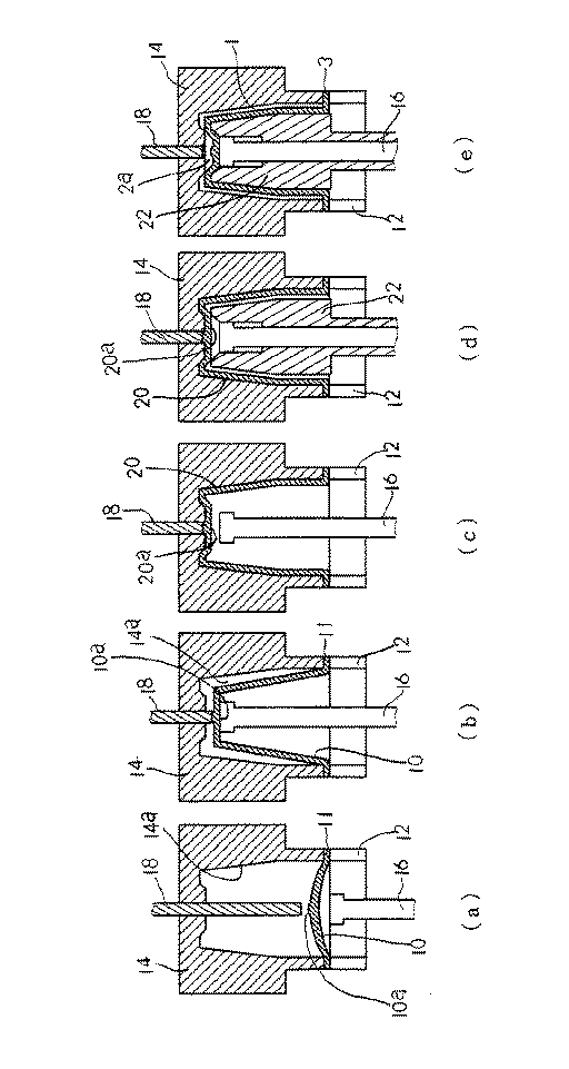
本発明のポリエステル容器は、上述した熱可塑性ポリエステル樹脂の射出成形により成形されたシート状でほぼ円板形状のプリフォーム(前成形体)を、所定の熱成形温度に加熱し、図2に示す(a)〜(e)の工程で延伸成形することにより製造される。
(Manufacture of containers)
The polyester container of the present invention heats a sheet-like, substantially disk-shaped preform (pre-molded body) formed by injection molding of the above-described thermoplastic polyester resin to a predetermined thermoforming temperature, and is shown in FIG. It is manufactured by stretch molding in the steps (a) to (e).
このプリフォーム(図2において10で示す)は、実質上非晶質の状態で得られ、その中心部分(図2において10aで示す)には、前述した底部2の中心部に対応する厚肉部が形成されている。即ち、この厚肉部は、射出成形機の射出ゲートに対応する射出ゲート残部である。先に述べたように、射出成形以外の成形方法によってプリフォームを成形する場合には、このような厚肉部は形成されないため、他の成形方法で成形されたプリフォームを用いる場合には、このような厚肉部を積極的に形成しておくことが必要である。 This preform (indicated by 10 in FIG. 2) is obtained in a substantially amorphous state, and a thick portion corresponding to the central portion of the bottom 2 described above is formed in the central portion (indicated by 10a in FIG. 2). The part is formed. That is, this thick part is the remaining injection gate corresponding to the injection gate of the injection molding machine. As described above, when a preform is molded by a molding method other than injection molding, such a thick portion is not formed, so when using a preform molded by another molding method, It is necessary to actively form such a thick portion.
プリフォームの加熱温度は、該プリフォームを構成する熱可塑性ポリエステル樹脂のガラス転移点温度(Tg)以上で且つ結晶化開始温度(Tic)未満であるのが好ましい。加熱温度がガラス転移点温度(Tg)より小さいと、以下に述べる工程での熱成形に過大な力を必要とする。一方、結晶化開始温度(Tic)以上となると球晶が形成されて透明性が損なわれる傾向がある。尚、明細書中で使用するガラス転移点温度(Tg)及び結晶化開始温度(Tic)は、測定対象とする成形体より任意に約10mgを採取して、示差走査熱量計(DSC)を用い、窒素ガス雰囲気下において300℃で3分間ホールドした後室温まで急冷し、加熱速度毎分20℃で昇温して得たDSC曲線より求めたものに基づいている。 The heating temperature of the preform is preferably not less than the glass transition temperature (Tg) of the thermoplastic polyester resin constituting the preform and less than the crystallization start temperature (Tic). When the heating temperature is lower than the glass transition temperature (Tg), an excessive force is required for thermoforming in the process described below. On the other hand, when the temperature is equal to or higher than the crystallization start temperature (Tic), spherulites are formed and transparency tends to be impaired. As for the glass transition temperature (Tg) and crystallization start temperature (Tic) used in the specification, about 10 mg is arbitrarily sampled from the molded article to be measured, and a differential scanning calorimeter (DSC) is used. Based on a DSC curve obtained by holding at 300 ° C. for 3 minutes in a nitrogen gas atmosphere, rapidly cooling to room temperature, and heating at a heating rate of 20 ° C. per minute.
型締め工程[図2(a)]
先ず、図2(a)に示されているように、上記温度に加熱されているプリフォーム10を、環状締付部材12を用いて成形金型(雌金型)14上に型締めして保持する。
Clamping process [Fig. 2 (a)]
First, as shown in FIG. 2A, the preform 10 heated to the above temperature is clamped on a molding die (female die) 14 using an annular clamping member 12. Hold.
図2(a)において、環状の締付部材12と成形金型14とによって挟持されているプリフォーム10の周縁部分11は、前述した容器のフランジ3に対応する部分となる。 In FIG. 2A, the peripheral portion 11 of the preform 10 sandwiched between the annular fastening member 12 and the molding die 14 corresponds to the aforementioned flange 3 of the container.
環状締付部材12の間からはストレッチロッド16が延びており、また成形金型14の中央部分には、連通孔が形成されており、この連通孔を介して冷却用ロッド18が延びている。これらロッドは、何れも上下動可能となっており、特に冷却用ロッド18は、ストレッチロッド16に追随可能となっている。また、冷却用ロッド18の先端面は、通常、プリフォーム10の中心部10aに形成されている厚肉部の全体と接触し得る程度の大きさであり、ストレッチロッド16の先端面の大きさは、冷却用ロッド18の先端面よりも大きく形成されている。
A stretch rod 16 extends from between the annular fastening members 12, and a communication hole is formed in the central portion of the molding die 14, and a cooling
上記のストレッチロッド16及び冷却用ロッド18には、図示されていないが、その軸方向にガス流路が形成されている。
The stretch rod 16 and the cooling
プリフォーム10の周縁部11は予め公知の方法で加熱し、熱結晶化させ、耐熱性を付与しておいても良いが、図2(a)示されているように、プリフォーム10の周縁部分11は、成形金型14と環状締付部材12とによって挟持されるが、その締め付け圧力を高くし、例えば4.5乃至13MPa程度の圧力で加圧することが好ましい。このように高圧力で締め付けを行うと、ガラス転移点温度以上に加熱されている周縁部分11が延伸せしめられて、その厚さが例えば1/3乃至1/2程度に低減せしめられると共に、樹脂の流動によって配向結晶化せしめられ、耐熱性を付与することができる。 The peripheral portion 11 of the preform 10 may be preliminarily heated and thermally crystallized by a known method to impart heat resistance. However, as shown in FIG. The portion 11 is sandwiched between the molding die 14 and the annular fastening member 12, and it is preferable to increase the fastening pressure, for example, pressurizing with a pressure of about 4.5 to 13 MPa. When tightening at such a high pressure, the peripheral portion 11 heated to the glass transition temperature or higher is stretched, and the thickness thereof is reduced to, for example, about 1/3 to 1/2. It is possible to impart heat resistance by orientation crystallization by the flow of.
上記のような加圧締め付けによる配向結晶化(樹脂の流動)を促進するためには、プリフォーム10の周縁部11の上面、下面、環状締付部材12の下面或いは成形金型14の上面のいずれかにシリコンオイルの如き適宜の潤滑剤を塗布するのが好適である。 In order to promote orientation crystallization (resin flow) by pressure clamping as described above, the upper and lower surfaces of the peripheral edge 11 of the preform 10, the lower surface of the annular clamping member 12, or the upper surface of the molding die 14 It is preferable to apply an appropriate lubricant such as silicone oil to either of them.
延伸工程[図2(b)]:
上記のプリフォーム10の型締め工程に続いて、図2(b)に示すように延伸が行われる。即ち、この延伸工程では、ストレッチロッド16を伸長させ、このストレッチロッド16と冷却用ロッド18との間にプリフォーム10の中央部分10a(図1の容器の底部中心の厚肉部2aに相当)を挟み込み、ストレッチロッド16による軸方向延伸及びブロー延伸を行う。
Stretching step [FIG. 2 (b)]:
Following the above-described mold clamping step of the preform 10, stretching is performed as shown in FIG. In other words, in this stretching step, the stretch rod 16 is extended, and the central portion 10a of the preform 10 between the stretch rod 16 and the cooling rod 18 (corresponding to the thick portion 2a at the center of the bottom of the container in FIG. 1). Are stretched in the axial direction and blow stretched by the stretch rod 16.
図2(b)において、ストレッチロッド16による軸方向延伸は、該ロッド16を軸方向に伸長させることにより行われるが、この際、冷却用ロッド18は、ストレッチロッド16の伸長に追随するように移動する。即ち、これらロッド16,18に挟持されている部分(プリフォーム10の中央部分10a)には過度の圧力が作用せず、且つ、この部分は冷却用ロッド18によって冷却されているため、この部分での樹脂の流動が有効に抑制され、この結果、プリフォーム10の中央部分10a、即ち、容器の底部中心の厚肉部2aに相当する部分での配向結晶化が抑制され、従って、容器の底部中心の厚肉部2aに相当する部分では、非晶質状態がそのまま保持されることとなる。
In FIG. 2B, the axial stretching by the stretch rod 16 is performed by extending the rod 16 in the axial direction. At this time, the cooling
また、上記の軸方向延伸後、冷却用ロッド18は、成形金型14のキャビティ面14aよりも厚肉部の厚み分凹んだ位置まで後退し、ストレッチロッド16に形成されているガス流路から圧縮空気等の圧空が吹き出され、ブロー延伸が行われ、これにより、プリフォーム10の中心部分10aに厚肉部を残したままの状態で、プリフォーム10を成形金型14のキャビティ面14aの形状に賦形することができ、上記の中心部分10a以外の部分を配向結晶化し、耐熱性を高めることができる。
Moreover, after extending | stretching to said axial direction, the
熱固定工程[図2(c)]:
次いで、上記のようにして成形された延伸成形体20について、熱固定が行われる。熱固定は、熱固定温度に加熱された成形金型14のキャビティ面14aに延伸成形体20を接触させることにより、結晶化の促進と成形歪の緩和を行うものであり、これによって、さらに耐熱性を向上し且つ機械的強度を高めることができる。この熱固定温度は、プリフォーム10(延伸成形体20)を形成している熱可塑性ポリエステルの結晶化開始温度(Tic)より高温であるが融点(Tm)未満、特に融点(Tm)−10℃以下であることが好ましい(一般的には180℃程度である)。熱固定温度が融点(Tm)以上になると、延伸成形体20が成形金型14に溶着してしまうおそれがあり、結晶化開始温度(Tic)未満では結晶化、成形ひずみの緩和が不充分になり、耐熱性や強度が得られなくなってしまう。また、熱固定時間は、求められる耐熱性のレベルにもよるが、通常、0.5乃至5秒程度である。
Heat setting step [FIG. 2 (c)]:
Next, heat setting is performed on the stretched molded
ところで、本発明においては、上記の熱固定に際して、延伸成形体20の中央部20a(プリフォーム10の中央部10aに相当)は、成形金型14に接触しておらず、冷却用ロッド18に接触し、冷却されている。従って、射出ゲート残部である厚肉部が形成されているこの中央部20aに関しては、熱固定が行われず、この結果、非晶質状態が保持されたままとなり、その他の部分(例えば中央部20a以外の底部20b、胴部20c及びフランジ20d)について熱固定が行われる。即ち、厚肉部を有する中央部分20aを熱固定温度に加熱してしまうと、球晶が生成してしまい、耐衝撃性の低下や不透明化がもたらされるが、非晶質状態に保持せしめることにより、透明性を確保し、しかも非晶質に特有の可撓性、弾性等により耐衝撃性の低下も有効に回避することができる。
By the way, in the present invention, at the time of the above heat setting, the
本発明において、成形金型14の熱固定温度への加熱は、成形金型14の内部にヒータ等の加熱手段を設けることにより容易に行うことができる。また、このような加熱は、前述した延伸成形後に行ってもよいが、一般的には、予め成形金型14を熱固定温度に加熱しておき、この状態で、前述した締付工程及び延伸成形工程を実施し、熱固定終了後に加熱を停止するのがよい。 In the present invention, heating of the molding die 14 to the heat fixing temperature can be easily performed by providing heating means such as a heater inside the molding die 14. In addition, such heating may be performed after the above-described stretch molding, but generally, the molding die 14 is heated in advance to a heat fixing temperature, and in this state, the above-described tightening process and stretching are performed. It is preferable to perform the molding step and stop the heating after the heat setting.
また、冷却用ロッド18は、適当な冷媒などにより冷却されており、少なくとも延伸成形体20の中央部20aが熱固定温度未満(延伸工程時では、特にガラス転移温度未満)となるように、その温度が設定されているが、特に成形金型14が加熱されているため、その輻射熱等により、延伸成形体20或いはプリフォーム10の中央部分が、熱固定温度以上或いはガラス転移温度以上に上昇しないように留意すべきである。
Further, the cooling
コア挿入工程[図2(d)]及びシュリンクバック工程[図2(e)]:
本発明においては、上記の熱固定後、環状締付部材12の環状空間を通して、冷却用コア金型22を挿入する[図2(d)]。この冷却用コア金型22の外面形状は、図1で示す容器の形状に相当するものである。
Core insertion process [FIG. 2 (d)] and shrinkback process [FIG. 2 (e)]:
In the present invention, after the above heat fixing, the cooling core mold 22 is inserted through the annular space of the annular fastening member 12 [FIG. 2 (d)]. The outer surface shape of the cooling core mold 22 corresponds to the shape of the container shown in FIG.
コア金型22が挿入された後、冷却用ロッド18のガス流路から圧縮空気等の圧縮ガスが吹き付けられ、さらに必要により、ストレッチロッド16のガス流路を介しての減圧吸引が行われ、シュリンクバックが行われる[図2(e)]。このシュリンクバックにより、延伸成形体20は、最終容器形状に賦形され、且つ速やかに冷却され、これを取り出すことにより、図1に示す最終形状の容器を得ることができる。
After the core mold 22 is inserted, a compressed gas such as compressed air is blown from the gas flow path of the cooling
尚、上記のコア挿入工程及びシュリンクバック工程を行わず、延伸成形体20を最終容器形状とすることも可能ではあるが、この場合には、冷却に長時間要し、生産性が極めて低下する。このため、上記のようにコア挿入工程及びシュリンクバック工程を実施することが好ましく、これにより冷却時間を短縮し、生産性を著しく高めることができる。
Although it is possible to make the stretched molded
かくして上述した方法により、図1に示すような容器を得ることができ、この容器においては、底部2の中心部に形成されている厚肉部2aが実質上非晶質であり、他の部分が配向結晶化され且つ熱固定されているが、厚肉部2aでは配向結晶化されず且つ熱固定もされていない。この結果、優れた耐熱性と耐衝撃性とを示す。
Thus, the container as shown in FIG. 1 can be obtained by the method described above. In this container, the thick part 2a formed at the center of the
本発明の優れた効果を、次の実施例及び比較例で説明する。
[密度法]
次式の密度法により結晶化度を求めた。
結晶化度χc={[ρc×(ρ−ρa)]/[ρ×(ρc−ρa)]}×100
ρ :測定密度(g/cm3)
ρa :非晶密度(1.335g/cm3)
ρc :結晶密度(1.455g/cm3)
なお、密度測定は、n−ヘプタン−四塩化炭素系密度勾配管(株式会社池田理化製)により、20℃の条件下で行った。
The excellent effects of the present invention will be described in the following examples and comparative examples.
[Density method]
The crystallinity was determined by the density method of the following formula.
Crystallinity χc = {[ρc × (ρ−ρa)] / [ρ × (ρc−ρa)]} × 100
ρ: measured density (g / cm 3 )
ρa: amorphous density (1.335 g / cm 3 )
ρc: Crystal density (1.455 g / cm 3 )
In addition, the density measurement was performed on 20 degreeC conditions by the n-heptane-carbon tetrachloride type | system | group density gradient tube (made by Ikeda Rika Co., Ltd.).
容器の性能評価については、下記のように行った。
[耐熱性能]
空の容器を105℃のオーブン内に4分10秒保管処理し、その処理前後での満注内容積の変化率を測定して評価した。変化率が2%以下のとき、評価を○とした。
[耐衝撃性能]
容器に水200ml充填後密封し、80cmの高さから底部を下向きに落下させた。落下を5回繰り返した後、底部の変形を目視により確認し、割れがない場合を○とした。
[底部透明性]
スガ試験機(株)製ヘーズメーターを用いて、底部中心部の透明度(HAZE)を測定した。HAZEが10%以下のときを○とした。
The performance evaluation of the container was performed as follows.
[Heat resistance]
The empty container was stored in an oven at 105 ° C. for 4 minutes and 10 seconds, and the rate of change in the full volume before and after the processing was measured and evaluated. When the rate of change was 2% or less, the evaluation was ◯.
[Shock resistance]
The container was sealed after filling with 200 ml of water, and the bottom part was dropped downward from a height of 80 cm. After repeating the dropping five times, the deformation of the bottom portion was visually confirmed, and the case where there was no crack was marked as ◯.
[Bottom transparency]
The transparency (HAZE) at the center of the bottom was measured using a haze meter manufactured by Suga Test Instruments Co., Ltd. The case where HAZE was 10% or less was evaluated as ◯.
[実施例1]
固有粘度0.8dl/gのポリエチレンテレフタレート樹脂(三井化学(株)SA135、イソフタル酸2モル%含有)をインジェクション成形機(新潟鐵工所(株)NN75JS)に供給し、射出温度275〜300℃、射出圧10Kg/cm2の条件で射出成形し、単層で実質上非晶のプリフォーム15.6gを得た。
前記プリフォームのフランジ部を近赤外線ヒータの照射を用いて、180℃まで加熱し、熱結晶化させた。
前記プリフォームをガラス転移点以上の95℃に加熱した後、図2(a)〜(e)に記載した方法で、フランジ付きカップ容器を得た。
この際、成形金型温度は180℃、冷却用ロッド温度、冷却用コア金型温度は30℃であった。
表1に各工具寸法、結晶化度測定結果、各種性能評価結果を記載した。
底部中心部は非晶であり、中心部の周囲の底部が配向結晶化しているため、耐熱性、耐衝撃性とも実用上十分な性能を示した。
[Example 1]
A polyethylene terephthalate resin having an intrinsic viscosity of 0.8 dl / g (Mitsui Chemicals, Inc., SA135, containing 2 mol% of isophthalic acid) is supplied to an injection molding machine (Niigata Steel Corporation, NN75JS), and an injection temperature of 275 to 300 ° C. The injection pressure was 10 Kg / cm 2 , and injection molding was performed to obtain 15.6 g of a single layer substantially amorphous preform.
The flange portion of the preform was heated to 180 ° C. by using near-infrared heater irradiation to be thermally crystallized.
After the preform was heated to 95 ° C. above the glass transition point, a flanged cup container was obtained by the method described in FIGS.
At this time, the molding die temperature was 180 ° C., the cooling rod temperature, and the cooling core die temperature were 30 ° C.
Table 1 shows the tool dimensions, crystallinity measurement results, and various performance evaluation results.
Since the bottom center is amorphous and the bottom around the center is oriented and crystallized, both heat resistance and impact resistance showed practically sufficient performance.
[比較例1]
図2(a)〜(e)の中で冷却用ロッドを使用しない以外は、実施例と同条件でフランジ付きカップ容器を得た。
表1に各工具寸法、結晶化度測定結果、各種性能評価結果を記載した。
底部中心部は球晶であり、中心部の周囲の底部が配向結晶化しているため、耐熱性には優れるが、耐衝撃性については実用的な性能を示さなかった。
A flanged cup container was obtained under the same conditions as in the examples except that the cooling rod was not used in FIGS.
Table 1 shows the tool dimensions, crystallinity measurement results, and various performance evaluation results.
The center of the bottom part is spherulite, and the bottom part around the center part is oriented and crystallized, so that the heat resistance is excellent, but practical performance was not shown in terms of impact resistance.
1:容器胴部
2:容器の底部
2a:容器の底部中心に形成された厚肉部
3:容器のフランジ
10:プリフォーム
10a:プリフォームの中心部
11:プリフォームの周縁部
12:環状締付部材
14:成形金型
16:ストレッチロッド
18:冷却用ロッド
20:延伸成形体
22:冷却用コア金型
1: Container body portion 2: Bottom portion of container 2a: Thick wall portion formed at the center of the bottom portion of the container 3: Flange of the container 10: Preform 10a: Center portion of the preform 11: Peripheral portion of the preform 12: Ring tightening Attachment member 14: Molding die 16: Stretch rod 18: Cooling rod 20: Stretched molded body 22: Cooling core die
Claims (5)
底部中心部分が、実質上非晶質であり、該中心部分の周囲の底部は配向結晶化されていることを特徴とするポリエステルカップ容器。 In a polyester container obtained by stretching a preform made of a thermoplastic polyester resin,
A polyester cup container , wherein a bottom center portion is substantially amorphous, and a bottom portion around the center portion is oriented and crystallized.
前記プリフォームの射出ゲート残部を、ストレッチロッドと冷却ロッドとの間に挟み込み、
前記ストレッチロッドを伸長させ且つ冷却用ロッドをストレッチロッドに追随させて軸方向延伸を行い、さらに流体吹込みによるブロー延伸を行い、
前記ブロー延伸によって、前記冷却用ロッドが接触している部分を除き、延伸された成形体の外面を加熱保持された加熱金型表面に接触させて、該成形体をカップ形状に賦形するとともに、
前記加熱金型表面への接触によって、前記冷却用ロッドが接触している部分以外を加熱して熱固定を行う、
ことを特徴とするポリエステルカップ容器の製造方法。 A thermoplastic polyester resin preform is molded by injection molding.
The injection gate remainder of the preform is sandwiched between a stretch rod and a cooling rod,
Stretching the stretch rod and causing the cooling rod to follow the stretch rod to perform axial stretching, and further blow blowing by fluid blowing,
Except for the portion where the cooling rod is in contact with the blow stretching, the outer surface of the stretched molded body is brought into contact with the heated mold surface which is heated and held, and the molded body is shaped into a cup shape. ,
By heat contact with the surface of the heating mold, heat fixing is performed by heating other than the portion in contact with the cooling rod,
A method for producing a polyester cup container .
Priority Applications (6)
| Application Number | Priority Date | Filing Date | Title |
|---|---|---|---|
| JP2004221703A JP4635506B2 (en) | 2004-07-29 | 2004-07-29 | Polyester container excellent in heat resistance and impact resistance and production method thereof |
| US11/658,508 US7833467B2 (en) | 2004-07-27 | 2005-07-25 | Polyester container having excellent heat resistance and shock resistance and method of producing the same |
| CN2005800325962A CN101027177B (en) | 2004-07-27 | 2005-07-25 | Polyester container excellent in heat resistance and impact resistance and manufacturing method thereof |
| KR1020077004056A KR101199692B1 (en) | 2004-07-27 | 2005-07-25 | Polyester container having excellent heat resistance and shock resistance and method of producing the same |
| PCT/JP2005/013991 WO2006011612A1 (en) | 2004-07-27 | 2005-07-25 | Polyester container excellent in resistance to heat and impact, and method for production thereof |
| EP05767371.7A EP1772251B1 (en) | 2004-07-27 | 2005-07-25 | Polyester container excellent in resistance to heat and impact, and method for production thereof |
Applications Claiming Priority (1)
| Application Number | Priority Date | Filing Date | Title |
|---|---|---|---|
| JP2004221703A JP4635506B2 (en) | 2004-07-29 | 2004-07-29 | Polyester container excellent in heat resistance and impact resistance and production method thereof |
Publications (2)
| Publication Number | Publication Date |
|---|---|
| JP2006035747A JP2006035747A (en) | 2006-02-09 |
| JP4635506B2 true JP4635506B2 (en) | 2011-02-23 |
Family
ID=35901233
Family Applications (1)
| Application Number | Title | Priority Date | Filing Date |
|---|---|---|---|
| JP2004221703A Expired - Fee Related JP4635506B2 (en) | 2004-07-27 | 2004-07-29 | Polyester container excellent in heat resistance and impact resistance and production method thereof |
Country Status (1)
| Country | Link |
|---|---|
| JP (1) | JP4635506B2 (en) |
Families Citing this family (3)
| Publication number | Priority date | Publication date | Assignee | Title |
|---|---|---|---|---|
| US8968636B2 (en) * | 2010-10-15 | 2015-03-03 | Discma Ag | Stretch rod system for liquid or hydraulic blow molding |
| JP2017145046A (en) * | 2016-02-17 | 2017-08-24 | 吉村化成株式会社 | Adiabatic container, method for manufacturing adiabatic container, inner container of adiabatic container |
| JP7541428B1 (en) * | 2024-04-25 | 2024-08-28 | 株式会社フロンティア | Method for manufacturing primary molded body and multipack |
Family Cites Families (8)
| Publication number | Priority date | Publication date | Assignee | Title |
|---|---|---|---|---|
| SE429317B (en) * | 1980-05-29 | 1983-08-29 | Plm Ab | SETTING ASTADCOMMENDING ANY POLYETHYLTENE PREPARATE OR ITS LIKE THERMOPLASTIC MATERIAL AS A DEVICE FOR THIS |
| JPH0735085B2 (en) * | 1990-10-05 | 1995-04-19 | 日精エー・エス・ビー機械株式会社 | Biaxially stretched crystalline resin container and method for producing the same |
| JPH0671762B2 (en) * | 1991-04-30 | 1994-09-14 | 日精エー・エス・ビー機械株式会社 | Injection stretch blow molding method for hollow body having thick bottom wall |
| JPH05246416A (en) * | 1992-02-29 | 1993-09-24 | Nissei Asb Mach Co Ltd | Self-standing bottle of synthetic resin |
| JP2998559B2 (en) * | 1994-05-13 | 2000-01-11 | 東洋製罐株式会社 | One-piece heat-resistant polyester bottle and its manufacturing method |
| JP3676426B2 (en) * | 1995-05-25 | 2005-07-27 | 北海製罐株式会社 | Polyethylene terephthalate resin bottle |
| JP3449182B2 (en) * | 1997-07-29 | 2003-09-22 | 東洋製罐株式会社 | Manufacturing method of heat-resistant stretched resin container |
| JP2003159743A (en) * | 2001-11-28 | 2003-06-03 | Toyo Seikan Kaisha Ltd | Manufacturing method of synthetic resin container |
-
2004
- 2004-07-29 JP JP2004221703A patent/JP4635506B2/en not_active Expired - Fee Related
Also Published As
| Publication number | Publication date |
|---|---|
| JP2006035747A (en) | 2006-02-09 |
Similar Documents
| Publication | Publication Date | Title |
|---|---|---|
| JP5533515B2 (en) | Polyester expanded foam container | |
| JPH036061B2 (en) | ||
| CN100369737C (en) | Molded article prepared by stretching and heat setting and method for producing the same | |
| CN101027177B (en) | Polyester container excellent in heat resistance and impact resistance and manufacturing method thereof | |
| WO2007138842A1 (en) | Biodegradable stretch-molded container having excellent heat resistance | |
| CA2288742C (en) | Improved multi-layer container and preform | |
| JP2003191319A (en) | Bottle-shaped container and manufacturing method thereof | |
| JP4635506B2 (en) | Polyester container excellent in heat resistance and impact resistance and production method thereof | |
| WO2006030972A1 (en) | Flat container comprising thermoplastic resin and method for molding the same | |
| JP4333280B2 (en) | Plastic bottle containers | |
| US6562279B2 (en) | Multi-layer container and preform and process for obtaining same | |
| US6413600B1 (en) | Multi-layer container and preform and process for obtaining same | |
| WO2019017395A1 (en) | Polyester resin container, method for producing same, and blow mould | |
| JP4282364B2 (en) | Heat-resistant wide-mouth synthetic resin container, manufacturing method and manufacturing apparatus | |
| JP4148065B2 (en) | Stretch blow molding method of plastic bottle container and plastic bottle container formed by this molding method | |
| JPH01157828A (en) | Heat-setting polyester orientation molding container | |
| JP2005112440A (en) | Container | |
| JP2886292B2 (en) | Saturated polyester resin bottle and method for producing the same | |
| JP5446553B2 (en) | Plastic bottle for heating | |
| JPS63185620A (en) | Production of thermally set polyester stretched molded container | |
| JP2004291621A (en) | Manufacturing method of thermoplastic resin container | |
| JP3802970B2 (en) | Propylene polymer container excellent in impact resistance and method for producing the same | |
| JP4449312B2 (en) | Method for manufacturing thermoplastic resin container | |
| JP2727934B2 (en) | Vacuum absorbent polyester bottle | |
| JP4878001B2 (en) | Plastic plastic blow container |
Legal Events
| Date | Code | Title | Description |
|---|---|---|---|
| A621 | Written request for application examination |
Free format text: JAPANESE INTERMEDIATE CODE: A621 Effective date: 20070608 |
|
| A131 | Notification of reasons for refusal |
Free format text: JAPANESE INTERMEDIATE CODE: A131 Effective date: 20100202 |
|
| A521 | Request for written amendment filed |
Free format text: JAPANESE INTERMEDIATE CODE: A523 Effective date: 20100324 |
|
| TRDD | Decision of grant or rejection written | ||
| A01 | Written decision to grant a patent or to grant a registration (utility model) |
Free format text: JAPANESE INTERMEDIATE CODE: A01 Effective date: 20101026 |
|
| A01 | Written decision to grant a patent or to grant a registration (utility model) |
Free format text: JAPANESE INTERMEDIATE CODE: A01 |
|
| A61 | First payment of annual fees (during grant procedure) |
Free format text: JAPANESE INTERMEDIATE CODE: A61 Effective date: 20101108 |
|
| FPAY | Renewal fee payment (event date is renewal date of database) |
Free format text: PAYMENT UNTIL: 20131203 Year of fee payment: 3 |
|
| R150 | Certificate of patent or registration of utility model |
Ref document number: 4635506 Country of ref document: JP Free format text: JAPANESE INTERMEDIATE CODE: R150 Free format text: JAPANESE INTERMEDIATE CODE: R150 |
|
| FPAY | Renewal fee payment (event date is renewal date of database) |
Free format text: PAYMENT UNTIL: 20131203 Year of fee payment: 3 |
|
| S531 | Written request for registration of change of domicile |
Free format text: JAPANESE INTERMEDIATE CODE: R313531 |
|
| FPAY | Renewal fee payment (event date is renewal date of database) |
Free format text: PAYMENT UNTIL: 20131203 Year of fee payment: 3 |
|
| R350 | Written notification of registration of transfer |
Free format text: JAPANESE INTERMEDIATE CODE: R350 |
|
| S533 | Written request for registration of change of name |
Free format text: JAPANESE INTERMEDIATE CODE: R313533 |
|
| FPAY | Renewal fee payment (event date is renewal date of database) |
Free format text: PAYMENT UNTIL: 20131203 Year of fee payment: 3 |
|
| R350 | Written notification of registration of transfer |
Free format text: JAPANESE INTERMEDIATE CODE: R350 |
|
| S111 | Request for change of ownership or part of ownership |
Free format text: JAPANESE INTERMEDIATE CODE: R313111 |
|
| R350 | Written notification of registration of transfer |
Free format text: JAPANESE INTERMEDIATE CODE: R350 |
|
| LAPS | Cancellation because of no payment of annual fees |