JP2013023227A - Heat labile molded plastic bottle - Google Patents
Heat labile molded plastic bottle Download PDFInfo
- Publication number
- JP2013023227A JP2013023227A JP2011156702A JP2011156702A JP2013023227A JP 2013023227 A JP2013023227 A JP 2013023227A JP 2011156702 A JP2011156702 A JP 2011156702A JP 2011156702 A JP2011156702 A JP 2011156702A JP 2013023227 A JP2013023227 A JP 2013023227A
- Authority
- JP
- Japan
- Prior art keywords
- plastic bottle
- heat
- molded plastic
- resistant molded
- boundary surface
- Prior art date
- Legal status (The legal status is an assumption and is not a legal conclusion. Google has not performed a legal analysis and makes no representation as to the accuracy of the status listed.)
- Pending
Links
Images


Abstract
Description
本発明は、加温用の非耐熱成形プラスチックボトルに係り、とりわけホットウォーマーまたは自動販売機において加温される飲料用等の加温用の非耐熱成形プラスチックボトルに関する。 The present invention relates to a non-heat-resistant molded plastic bottle for heating, and more particularly to a non-heat-resistant molded plastic bottle for heating such as for beverages heated in a hot warmer or a vending machine.
近時、飲料用等のボトルとして、プラスチック製のものが一般化してきており、このようなプラスチック製ボトルには加温飲料用に用いられるものも多くなってきている。 Recently, plastic bottles for beverages and the like have become common, and such plastic bottles are increasingly used for heated beverages.
このような加温用のプラスチックボトルに求められる性能として、加温時にボトル外観を損なわないことが挙げられる。 The performance required for such a plastic bottle for heating is that the bottle appearance is not impaired during heating.
ところで、ボトル飲料製品の製造方法としては、無菌(アセプティック)充填方式が存在している。この無菌充填方式においては、無菌環境下でプラスチックボトル内を薬剤で滅菌し、次に滅菌されたプラスチックボトル内に常温で内容液を充填する手法を採用している。 By the way, as a method for producing a bottled beverage product, an aseptic filling method exists. This aseptic filling method employs a technique in which a plastic bottle is sterilized with a drug in an aseptic environment, and then the sterilized plastic bottle is filled with a content liquid at room temperature.
このような無菌充填方式を用いる場合、プラスチックボトルはその製造工程で高温に晒されることがない。したがって、無菌充填用のプラスチックボトルとしては、一般に耐熱性が低いボトル(非耐熱成形ボトル)が用いられている。しかしながら、このような非耐熱成形ボトルは、耐熱成形ボトルと比較して軽量かつ薄肉であるため、ボトル内圧の変化に伴って変形が生じ、外観が損なわれやすい。 When such an aseptic filling method is used, the plastic bottle is not exposed to high temperatures in the manufacturing process. Therefore, as a plastic bottle for aseptic filling, generally a bottle having low heat resistance (non-heat-resistant molded bottle) is used. However, since such a non-heat-resistant molded bottle is lighter and thinner than a heat-resistant molded bottle, deformation occurs with changes in the bottle internal pressure, and the appearance tends to be impaired.
本発明はこのような点を考慮してなされたものであり、飲料用のボトルとして薄肉の非耐熱成形ボトルを用いた場合であっても、非耐熱成形ボトル内に内容液を充填後にボトルを加熱した際、ボトル外観を良好に維持することが可能な加温用の非耐熱成形プラスチックボトルを提供することを目的とする。 The present invention has been made in consideration of such points, and even when a thin-walled non-heat-resistant molded bottle is used as a beverage bottle, the bottle is not used after filling the non-heat-resistant molded bottle with the content liquid. An object of the present invention is to provide a non-heat-resistant molded plastic bottle for heating that can maintain a good bottle appearance when heated.
本発明は、非耐熱成形プラスチックボトルにおいて、口部と、胴部と、底部とを備え、胴部は、複数の側面を有する略多角筒形状からなり、胴部の隣接する側面同士の間にそれぞれ境界面が形成され、各境界面に、内側に引込むとともに胴部の軸線方向に延びる複数の胴部凹状リブが設けられ、このうち一対の胴部凹状リブは当該境界面と隣接する側面との間の一対の稜線上に位置することを特徴とする非耐熱成形プラスチックボトルである。 The present invention relates to a non-heat-resistant molded plastic bottle, comprising a mouth portion, a trunk portion, and a bottom portion, the trunk portion having a substantially polygonal cylinder shape having a plurality of side surfaces, and between the adjacent side surfaces of the trunk portion. Each of the boundary surfaces is formed, and each of the boundary surfaces is provided with a plurality of trunk concave ribs that are drawn inward and extend in the axial direction of the trunk, and among these, the pair of trunk concave ribs is a side surface adjacent to the boundary surface. It is a non-heat-resistant molded plastic bottle characterized by being located on a pair of ridgeline between.
本発明は、非耐熱成形プラスチックボトルにおいて、口部と、胴部と、底部とを備え、胴部は、複数の側面を有する略多角筒形状からなり、底部は周縁部と、周縁部の中央に位置するとともに周縁部より上方に持上げられた中央部とを有し、周縁部に内側に引込むとともに放射状に延びる複数の底部凹状リブが設けられていることを特徴とする非耐熱成形プラスチックボトルである。 The present invention relates to a non-heat-resistant molded plastic bottle, comprising a mouth portion, a body portion, and a bottom portion, the body portion having a substantially polygonal cylinder shape having a plurality of side surfaces, the bottom portion being a peripheral portion and the center of the peripheral portion. A non-heat-resistant molded plastic bottle having a central portion lifted above the peripheral portion and having a plurality of bottom concave ribs extending inward and radially extending to the peripheral portion. is there.
本発明は、非耐熱成形プラスチックボトルにおいて、口部と、胴部と、底部とを備え、胴部は、複数の側面を有する略多角筒形状からなり、胴部の隣接する側面同士の間にそれぞれ境界面が形成され、各境界面に、内側に引込むとともに胴部の軸線方向に延びる複数の胴部凹状リブが設けられ、このうち一対の胴部凹状リブは当該境界面と隣接する側面との間の一対の稜線上に位置し、底部は周縁部と、周縁部の中央に位置するとともに周縁部より上方へ持上げられた中央部とを有し、周縁部に内側へ引込むとともに放射状に延びる複数の底部凹状リブが設けられていることを特徴とする非耐熱成形プラスチックボトルである。 The present invention relates to a non-heat-resistant molded plastic bottle, comprising a mouth portion, a trunk portion, and a bottom portion, the trunk portion having a substantially polygonal cylinder shape having a plurality of side surfaces, and between the adjacent side surfaces of the trunk portion. Each of the boundary surfaces is formed, and each of the boundary surfaces is provided with a plurality of trunk concave ribs that are drawn inward and extend in the axial direction of the trunk, and among these, the pair of trunk concave ribs is a side surface adjacent to the boundary surface. The bottom part has a peripheral part and a central part located at the center of the peripheral part and lifted upward from the peripheral part. The bottom part is drawn inwardly and extends radially. A non-heat-resistant molded plastic bottle provided with a plurality of bottom concave ribs.
本発明は、胴部の各側面に、それぞれ平板状のパネル部が形成されていることを特徴とする非耐熱成形プラスチックボトルである。 The present invention is a non-heat-resistant molded plastic bottle in which a flat panel portion is formed on each side surface of the body portion.
本発明は、各境界面の中央部に、更に他の胴部凹状リブが設けられていることを特徴とする非耐熱成形プラスチックボトルである。 The present invention is a non-heat-resistant molded plastic bottle characterized in that another barrel-shaped concave rib is further provided at the center of each boundary surface.
本発明は、胴部の各側面は、内側へ引込む側面水平凹状リブを介して上方領域と下方領域とに区画され、胴部の各境界面は、内側へ引込む境界面水平凹状リブを介して上方領域と下方領域とに区画され、各境界面の上方領域および下方領域に、各々複数の胴部凹状リブが設けられていることを特徴とする非耐熱成形プラスチックボトルである。 In the present invention, each side surface of the body portion is divided into an upper region and a lower region via side horizontal concave ribs that are drawn inward, and each boundary surface of the body portion is interposed via a boundary surface horizontal concave rib that is drawn inwardly. A non-heat-resistant molded plastic bottle characterized in that it is divided into an upper region and a lower region, and a plurality of body-shaped concave ribs are provided in the upper region and the lower region of each boundary surface.
本発明は、底部凹状リブは、底部の周縁部のうち、各側面の両側部に対応する部分に設けられていることを特徴とする非耐熱成形プラスチックボトルである。 The present invention is the non-heat-resistant molded plastic bottle, wherein the bottom concave rib is provided in a portion corresponding to both side portions of each side surface in the peripheral portion of the bottom portion.
本発明によれば、胴部の側面同士の間に形成された各境界面に内側に引込むとともに胴部の軸線方向に延びる複数の胴部凸状リブが設けられ、このうち一対の胴部凹状リブは境界面と隣接する側面との間の一対の稜線上に設けられているため、ボトルの加温時に、内容液からの圧力が加わり易い境界面の稜線の強度を高めることができる。 According to the present invention, each of the boundary surfaces formed between the side surfaces of the body portion is provided with a plurality of body-shaped convex ribs that are drawn inward and extend in the axial direction of the body portion, and of these, a pair of body portion concave shapes Since the ribs are provided on a pair of ridge lines between the boundary surface and the adjacent side surfaces, the strength of the ridge line of the boundary surface where pressure from the content liquid is easily applied when the bottle is heated can be increased.
また底部の周縁部に内側へ引込むとともに放射状に延びる複数の底部凹状リブが設けられているため、底部の中央部を押し上げて内容液を減圧充填する際、底部の周縁部が屈曲することはない。 In addition, since a plurality of bottom concave ribs that are drawn inwardly and extend radially to the peripheral portion of the bottom portion are provided, the peripheral portion of the bottom portion is not bent when the central portion of the bottom portion is pushed up to fill the content liquid under reduced pressure. .
以下、図面を参照して本発明の一実施の形態について説明する。図1乃至図9は本発明の一実施の形態を示す図である。 Hereinafter, an embodiment of the present invention will be described with reference to the drawings. 1 to 9 show an embodiment of the present invention.
まず、図1乃至図9により、本実施の形態による加温用の非耐熱成形プラスチックボトルの概要について説明する。 First, an outline of a non-heat-resistant molded plastic bottle for heating according to the present embodiment will be described with reference to FIGS.
図1乃至図9に示す加温用プラスチックボトル10は、無菌充填方式で用いられている非耐熱成形ボトルからなっている。ここで非耐熱成形ボトルとは、後述する口部11が非結晶の透明体からなり、口部11が薬剤により殺菌されるため高温下に晒されることはなく、耐熱性を有しないものである(図10(a)参照)。
A heating
非耐熱成形ボトルを作製する場合、まず金型が加熱されて、1次ブロー成形および2次ブロー成形が順次行なわれる。次に冷却ブローを施すことなく、その後金型内が排気される。 When producing a non-heat-resistant molded bottle, first, a metal mold | die is heated and primary blow molding and secondary blow molding are performed sequentially. Next, the inside of the mold is exhausted without cooling blow.
非耐熱成形ボトルの作製にあたって、金型温度は90℃未満に設定され、冷却ブロー工程がない分だけ生産効率が高くなっている。 In producing the non-heat-resistant molded bottle, the mold temperature is set to less than 90 ° C., and the production efficiency is increased by the absence of the cooling blow process.
一方、耐熱成形ボトルとは、口部11が結晶化された白色体からなり、高温の内容液により口部11を殺菌するため耐熱性が必要となる(図10(b)参照)。
On the other hand, the heat-resistant molded bottle is made of a white body in which the
耐熱成形ボトルを作製する場合、まず金型が加熱されて、1次ブロー成形および2次ブロー成形が順次行なわれる。次に離型後に収縮しないよう、2次ブロー成形の直後に金型内を排気しながら冷却ブローが施される。
耐熱成形ボトルの作製にあたって、金型温度は90℃以上に設定され、冷却ブロー工程をもつため生産時間は長くなる。
When producing a heat-resistant molded bottle, the mold is first heated, and primary blow molding and secondary blow molding are sequentially performed. Next, cooling blow is performed while exhausting the inside of the mold immediately after the secondary blow molding so as not to shrink after the mold release .
In producing the heat-resistant molded bottle, the mold temperature is set to 90 ° C. or more, and the production time becomes long because of the cooling blow process.
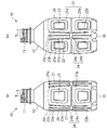
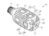
このような加温用の非耐熱成形プラスチックボトル10は、口部11と、口部11下方に設けられた肩部12と、肩部12下方に設けられた胴部20と、胴部20下方に設けられた底部30とを備えている。
Such a non-heat-resistant molded
このうち胴部20は、互いに同一の形状からなる複数、例えば4つの側面21を有しており、全体として略多角筒形状、例えば四角筒形状からなっている。また隣接する側面21同士の間には、それぞれ平坦な境界面22が形成されている。
Among these, the trunk | drum 20 has several, for example, four
また胴部20の4つの側面21は、内側へ(ボトル10の内方へ)引込む側面水平凹状リブ24aを介して上方領域21aと、下方領域21bとに区画されている。また各境界面22も内側へ(ボトル10の内方へ)引込む境界面水平凹状リブ24bを介して上方領域22aと、下方領域22bとに区画されている。
Moreover, the four
このうち側面水平凹状リブ24aと境界面水平凹状リブ24bとによって水平凹状リブ24が構成されている。
Among these, the horizontal
また、胴部20の各側面21の上方領域21aおよび下方領域21bには、各々平板状のパネル部23が設けられ、このパネル部23によってプラスチックボトル10内の膨張時および減圧時にプラスチックボトル10に加わる圧力を吸収している。
Further, a
さらに胴部20の各境界面22の上方領域22aおよび下方領域22bには、各々内側へ(ボトル10の内方へ)引込むとともに、胴部20の軸線方向L方向(図1(a)(b)参照)に延びる複数例えば3本の胴部凹状リブ25a、25b、25cが設けられている。
Further, the
上述のように、胴部20の側面21および境界面22は、各々合計4つ設けられ、1つの境界面22の上方領域22aおよび下方領域22bに各々3本の胴部凹状リブ25a、25b、25cが設けられている。このためプラスチックボトル10全体として、合計24本の胴部凹状リブ25a、25b、25cが設けられている。
As described above, a total of four
ところで胴部20の各境界面22の上方領域22aに設けられた3本の胴部凹状リブ25a、25b、25cのうち、一対の胴部凹状リブ25a、25bは、境界面22の上方領域22aのうち隣接する側面21の上方領域21aとの間の一対の稜線上(境界面22の上方領域22aの両側縁上)に設けられている。また、残りの1本の胴部凹状リブ(他の胴部凹状リブ)25cは一対の胴部凹状リブ25a、25b間であって上方領域22aの中央部に設けられている。
By the way, out of the three barrel
同様に各境界面22の下方領域22bに設けられた3本の胴部凹状リブ25a、25b、25cのうち、一対の胴部凹状リブ25a、25bは境界面22の下方領域22bのうち隣接する側面21の下方領域21bとの間の一対の稜線上(境界面22の下方領域22bの両側縁上)に設けられている。また残りの1本の胴部凹状リブ(他の胴部凹状リブ)25cは、一対の胴部凹状リブ25a、25b間であって下方領域22bの中央部に設けられている。
Similarly, of the three body
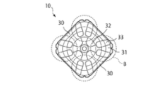
さらにまた、底部30は周縁部31と、周縁部31の中央に位置するとともに周縁部31より上方へ持上げられた中央部32とを有し、周縁部31に放射状に延びる複数、例えば8本の底部凹状リブ33が設けられている。8本の底部凹状リブ33はいずれも内側へ(ボトル10の内方へ)引込んで形成され、底部30の周縁部31の強度維持を図るものである。
Furthermore, the
ところで周縁部31に設けられた底部凹状リブ33は、胴部20の4つの側面21の両側部に対応する部分に設けられている。
By the way, the bottom
すなわち胴部20は4つの側面21を有し、各側面21の両側部に対応して底部凹状リブ33が設けられているため、上述のように合計8本の底部凹状リブ33が形成されている。
That is, the
ところで、各胴部凹状リブ25a、25b、25cおよび底部凹状リブ33は、いずれも同様の形状を有しており、例えば図9(a)に示すような断面湾曲形状を有している。あるいは各胴部凹状リブ25a、25b、25cおよび底部凹状リブ33を図9(b)に示すように断面三角形状に形成してもよく、図9(c)に示すように断面台形状に形成してもよい。さらに各胴部凹状リブ25a、25b、25cおよび底部凹状リブ33を断面多角形状に形成してもよい。
By the way, each trunk | drum
このような加温用の非耐熱成形プラスチックボトル10は、合成樹脂材料を射出成形して製作したプリフォームを二軸延伸ブロー成形することにより作製することができる。なおプリフォームすなわちプラスチックボトル10の材料としては熱可塑性樹脂、特にPE(ポリエチレン)、PP(ポリプロピレン)、PET(ポリエチレンテレフタレート)、PEN(ポリエチレンナフタレート)を使用する事が好ましい。
Such a non-heat-resistant molded
また、プラスチックボトル10は、2層以上の多層成形ボトルとして形成することもできる。即ち押し出し成形または射出成形により、例えば、中間層をMXD6、MXD6+脂肪酸塩、PGA(ポリグリコール酸)、EVOH(エチレンビニルアルコール共重合体)又はPEN(ポリエチレンナフタレート)等のガスバリア性及び遮光性を有する樹脂(中間層)として3層以上からなるプリフォームを押出成形後、吹込成形することによりガスバリア性及び遮光性を有する多層ボトルを形成しても良い。なお、このような中間層は、プラスチックボトル10のうち少なくとも胴部20内に設けることが好ましい。また底部30において、底部30の中央部を除く領域に中間層を設けることが好ましい。ケース落下等の衝撃を受けた際この部分がデラミ(層間剥離)を起こすおそれがあるからである。ガスバリア性及び遮光性を有する為に、多層にするだけでなく熱可塑性樹脂同士をブレンドしたブレンドボトルを形成しても良い。
The
次にこのような構成からなる本実施の形態の作用について説明する。 Next, the operation of the present embodiment having such a configuration will be described.
まずプラスチックボトル10内に、例えば緑茶、コーヒー等の内容液を充填し、その後これを密栓する。
First, the
この場合、プラスチックボトル10の底部30の中央部32を押し棒(図示せず)により押し上げた状態で、内容液がプラスチックボトル10内に充填される。
In this case, the content liquid is filled into the
底部30の中央部32を押し棒により押し上げる際、図5(a)(b)および図6に示す領域Bにおいて、底部30の周縁部31が屈曲することも考えられるが、底部30の周縁部31のうち、大きな力が加わると考えられる各側面21の両側部に対応する部分に、内側へ引込む底部凹状リブ33が設けられているため、この底部凹状リブ33により周縁部31の強度上昇を図ることができる。このため、底部30の中央部32を大きく押し棒により押し上げることができ、このことによりプラスチックボトル10内に内容液を充填しその後、密栓することにより、プラスチックボトル10内に内容液を減圧状態で充填することができる。
When the
次に胴部20周囲にシュリンクフィルム等のラベルを付す。その後、プラスチックボトル10は、ホットウォーマーまたは自動販売機において、加温された状態で販売される。
Next, a label such as a shrink film is attached around the
この際、プラスチックボトル10が加温されることにより、内容液も加温され、内容液の体積が増加する。これによりプラスチックボトル10のボトル内圧が増加する。またプラスチックボトル10のボトル内圧が増加することにより、胴部20が膨張する。
At this time, when the
この場合、図7に示すように、胴部20の各側面21が胴部20外方(外側ともいう)に向けて膨らむとともに、各境界面22が側面21の膨張に対応して胴部20内方(内側ともいう)へ向って湾曲する(図7の2点鎖線参照)。
In this case, as shown in FIG. 7, each
この際、各境界面22の上方領域22aおよび下方領域22bに各々胴部凹状リブ25a、25b、25cが設けられているので、各境界面22の強度を向上させることができる。とりわけ内容液からの力が加わる各境界面22の上方領域22aおよび下方領域22bのうち側面21との稜線上に一対の胴部凹状リブ25a、25bが設けられているため、各境界面22の上方領域22aおよび下方領域22bの強度をより向上させることができる。このため胴部20のうち各境界面22が形成される領域A(図5(a)(b)および図6参照)が大きく内方へ向って湾曲することはなく、かつ各側面21が大きく外方へ向って膨らむこともない。このことにより加温時のプラスチックボトル10の外観を良好に維持することができる。
At this time, since the trunk-shaped
また本実施の形態によれば、プラスチックボトル10は非耐熱成形ボトルから構成することができるため、内容液の充填方式として無菌充てん方式を採用することができる。このためボトルの内容液の風味を損なわず、かつ生産コストの低減を図ることが可能となる。
Moreover, according to this Embodiment, since the
なお、上記実施の形態において、胴部20の境界面22に胴部凹状リブ25a、25b、25cを設けるとともに、底部30の周縁部31に底部凹状リブ33を設けた例を示したが、これに限らず、境界面22に胴部凹状リブ25a、25b、25cを設けることなく、底部30の周縁部31のみに底部凹状リブ33を設けてもよい。また底部30の周縁部31に底部凹状リブ33を設けることなく、境界面22のみに胴部凹状リブ25a、25b、25cを設けてもよい。
In the above embodiment, an example in which the body
次に本実施の形態における具体的実施例について説明する。 Next, specific examples in the present embodiment will be described.
まず以下に挙げる4種類のプラスチックボトル(実施例1−3、比較例1)を作製した。 First, the following four types of plastic bottles (Example 1-3, Comparative Example 1) were produced.
(実施例1)
図1乃至図6に示す構成からなる345mlのプラスチックボトル10を作製した。
Example 1
A 345 ml
この場合、まず射出成形により22.7gのPET単層プリフォームを作製し、二軸延伸ブロー成形により345mlの四角筒状プラスチックボトル10を作製した。
In this case, a 22.7 g PET single layer preform was first produced by injection molding, and a 345 ml square cylindrical
このプラスチックボトル10内に25℃および70℃において、内容液を充填した後に底部30の中央部32を7mmだけ押上げてプラスチックボトル10を密栓した。なお70℃において、その後常温まで冷却した。
After filling the
その後プラスチックボトル10に対して、75℃×60minの湯煎を施し、湯煎前後において、プラスチックボトル10の寸法変化量を測定して耐熱性の傷劣を評価した。
Thereafter, a hot water bath at 75 ° C. × 60 min was applied to the
実施例1のプラスチックボトル10を形状Aとした。
The
(実施例2)
胴部凹状リブ25a、25b、25cを設けることなく、底部凹状リブ33のみを設けた点以外は、実施例1の構成と同一の構成からなる345mlのプラスチックボトル10を作製した。
(Example 2)
A 345 ml
この場合、まず射出成形により22.7gのPET単層プリフォームを作製し、二軸延伸ブロー成形により345mlの四角筒状プラスチックボトル10を作製した。
In this case, a 22.7 g PET single layer preform was first produced by injection molding, and a 345 ml square cylindrical
このプラスチックボトル10内に25℃および70℃において、内容液を充填した後に底部30の中央部32を7mmだけ押上げてプラスチックボトル10を密栓した。なお70℃において内容液を充填した場合は、その後常温まで冷却した。
After filling the
その後プラスチックボトル10に対して、75℃×60minの湯煎を施し、湯煎前後において、プラスチックボトル10の寸法変化量を測定して耐熱性の傷劣を評価した。
Thereafter, a hot water bath at 75 ° C. × 60 min was applied to the
実施例2のプラスチックボトル10を形状Bとした。
The
(実施例3)
胴部凹状リブ25a、25b、25cを設け、底部凹状リブ33を設けない点以外は、実施例1の構成と同一の構成からなる345mlのプラスチックボトル10を作製した。
(Example 3)
A 345 ml
この場合、まず射出成形により22.7gのPET単層プリフォームを作製し、二軸延伸ブロー成形により345mlの四角筒状プラスチックボトル10を作製した。
In this case, a 22.7 g PET single layer preform was first produced by injection molding, and a 345 ml square cylindrical
このプラスチックボトル10内に25℃および70℃において、内容液を充填した後に底部30の中央部32を3mmだけ押上げてプラスチックボトル10を密栓した。なお70℃において内容液を充填した場合は、その後常温まで冷却した。
After filling the
その後プラスチックボトル10に対して、75℃×60minの湯煎を施し、湯煎前後において、プラスチックボトル10の寸法変化量を測定して耐熱性の傷劣を評価した。
Thereafter, a hot water bath at 75 ° C. × 60 min was applied to the
実施例3のプラスチックボトル10を形状Cとした。
The
(比較例1)
胴部凹状リブ25a、25b、25cを設けることなく、かつ底部凹状リブ33を設けない点以外は、実施例と同様にして345mlのプラスチックボトル10を作製した。
(Comparative Example 1)
A 345 ml
この場合、まず射出成形により22.7gのPET単層プリフォームを作製し、二軸延伸ブロー成形により345mlの四角筒状プラスチックボトル10を作製した。
In this case, a 22.7 g PET single layer preform was first produced by injection molding, and a 345 ml square cylindrical
このプラスチックボトル10内に25℃および70℃において、内容液を充填した後に底部30の中央部32を3mmだけ押上げてプラスチックボトル10を密栓した。なお70℃において内容液を充填した場合は、その後常温まで冷却した。
After filling the
その後プラスチックボトル10に対して、75℃×60minの湯煎を施し、湯煎前後において、プラスチックボトル10の寸法変化量を測定して耐熱性の傷劣を評価した。
Thereafter, a hot water bath at 75 ° C. × 60 min was applied to the
比較例1のプラスチックボトル10を形状Dとした。
The
(底部30の周縁部31の屈曲性の評価)
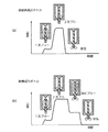
実施例1のプラスチックボトル10(形状A)と、比較例1のプラスチックボトル10(形状D)に対して、底部30の中央部32を押し棒で押し上げ、この場合の周縁部31の屈曲性を評価した。
(Evaluation of flexibility of the
With respect to the plastic bottle 10 (shape A) of Example 1 and the plastic bottle 10 (shape D) of Comparative Example 1, the
この評価結果を図8に示す。図8において、横軸に押し棒による中央部32の変位(mm)を示し、縦軸に押し棒による圧力(N)を示す。
The evaluation results are shown in FIG. In FIG. 8, the horizontal axis shows the displacement (mm) of the
図8に示すように、形状Aについては変位が10(mm)となるまで中央部32を変位させても、周縁部31に屈曲点が現われることはない。すなわち形状Aの場合、底部30の周縁部31に複数の底部凹状リブ33が設けられているため周縁部31の強度を増加させることができる。
As shown in FIG. 8, for the shape A, even if the
他方、形状Dについては、底部30の周縁部31に底部凹状リブ33は設けられておらず、このため底部30の中央部32を押し棒で押し上げた場合、複数の屈曲点Pが現われ、周縁部31に塑性変形が生じていることを示している。
On the other hand, with respect to the shape D, the bottom
具体的に言うと、図8において、形状Dにおいては、中央部32を3.4mm変位させた場合、最初の屈曲点Pが現われる。
Specifically, in FIG. 8, in the shape D, when the
このため形状Dに対しては、この最初の屈曲点P以下の範囲で中央部32を押し上げる必要がある。
Therefore, for the shape D, it is necessary to push up the
(耐熱性の評価)
次に形状A〜Dの耐熱性を評価するため、充填温度を25℃と70℃とした場合について、各々n=5のサンプルを作成し、プラスチックボトルを湯煎(75℃×60min)した際の寸法変形量を測定した。ここで寸法変化量としては、対向する2つの側面21間の寸法変化量の二乗と、対向する2つの境界面22間の寸法変化量の二乗の総和を求め、これを形状維持指数とした。
(Evaluation of heat resistance)
Next, in order to evaluate the heat resistance of the shapes A to D, when the filling temperature was set to 25 ° C. and 70 ° C., samples of n = 5 were respectively prepared, and the plastic bottle was boiled (75 ° C. × 60 min). The amount of dimensional deformation was measured. Here, as the dimensional change amount, the sum of the square of the dimensional change amount between the two opposing side surfaces 21 and the square of the dimensional change amount between the two opposing boundary surfaces 22 was obtained and used as the shape maintenance index.
また、内容液充填時における底部30の中央部32の押上げ量は、形状A−Bについては7mm、形状C−Dについては3mmとした。この形状維持指数を表1に示す。

表1からわかるように、形状A−Cについては、使用に耐えうる耐熱性評価が得られた。形状Dについては、70℃で内容液を充填した場合は大きな寸法変形はないが、25℃で内容物を充填した場合は大きな寸法変形が現われ、使用に耐えうる耐熱性評価は得られなかった。 As can be seen from Table 1, heat resistance evaluation that can withstand use was obtained for the shapes AC. Regarding shape D, when the content liquid was filled at 70 ° C., there was no large dimensional deformation, but when the content was filled at 25 ° C., large dimensional deformation appeared, and a heat resistance evaluation that could withstand use was not obtained. .
なお、表1において、プラスチックボトル10内に70℃で内容液を充填した場合は、プラスチックボトル10を一度室温まで冷却して収縮させた後、再度75℃まで湯煎して加温することにより膨張させることになる。他方、プラスチックボトル10内に25℃で内容液を充填した場合は、その後75℃まで湯煎して加温することにより単純に膨張させることになる。このため、形状A−Dのいずれについても、25℃で内容液を充填した場合の方が、70℃で内容物を充填する場合に比べて、寸法変化量が大きくなっている。
In Table 1, when the
10 プラスチックボトル
11 口部
12 肩部
20 胴部
21 側面
21a 上方領域
21b 下方領域
22 境界面
23 パネル部
24 水平凹状リブ
24a 側面水平凹状リブ
24b 境界面水平凹状リブ
25a、25b、25c 胴部凹状リブ
30 底部
31 周縁部
32 中央部
33 底部凹状リブ
DESCRIPTION OF
Claims (7)
口部と、
胴部と、
底部とを備え、
胴部は、複数の側面を有する略多角筒形状からなり、
胴部の隣接する側面同士の間にそれぞれ境界面が形成され、各境界面に、内側に引込むとともに胴部の軸線方向に延びる複数の胴部凹状リブが設けられ、このうち一対の胴部凹状リブは当該境界面と隣接する側面との間の一対の稜線上に位置することを特徴とする非耐熱成形プラスチックボトル。 In non-heat-resistant molded plastic bottles,
The mouth,
The torso,
With a bottom,
The trunk portion has a substantially polygonal cylinder shape having a plurality of side surfaces,
Boundary surfaces are formed between adjacent side surfaces of the body part, and a plurality of body-shaped concave ribs that are drawn inward and extend in the axial direction of the body part are provided on each boundary surface. The non-heat-resistant molded plastic bottle, wherein the rib is positioned on a pair of ridge lines between the boundary surface and the adjacent side surface.
口部と、
胴部と、
底部とを備え、
胴部は、複数の側面を有する略多角筒形状からなり、
底部は周縁部と、周縁部の中央に位置するとともに周縁部より上方に持上げられた中央部とを有し、周縁部に内側に引込むとともに放射状に延びる複数の底部凹状リブが設けられていることを特徴とする非耐熱成形プラスチックボトル。 In non-heat-resistant molded plastic bottles,
The mouth,
The torso,
With a bottom,
The trunk portion has a substantially polygonal cylinder shape having a plurality of side surfaces,
The bottom part has a peripheral part and a central part located at the center of the peripheral part and lifted above the peripheral part, and is provided with a plurality of bottom concave ribs that are drawn inward and extend radially to the peripheral part. Non-heat resistant molded plastic bottle.
口部と、
胴部と、
底部とを備え、
胴部は、複数の側面を有する略多角筒形状からなり、
胴部の隣接する側面同士の間にそれぞれ境界面が形成され、各境界面に、内側に引込むとともに胴部の軸線方向に延びる複数の胴部凹状リブが設けられ、このうち一対の胴部凹状リブは当該境界面と隣接する側面との間の一対の稜線上に位置し、
底部は周縁部と、周縁部の中央に位置するとともに周縁部より上方へ持上げられた中央部とを有し、周縁部に内側へ引込むとともに放射状に延びる複数の底部凹状リブが設けられていることを特徴とする非耐熱成形プラスチックボトル。 In non-heat-resistant molded plastic bottles,
The mouth,
The torso,
With a bottom,
The trunk portion has a substantially polygonal cylinder shape having a plurality of side surfaces,
Boundary surfaces are formed between adjacent side surfaces of the body part, and a plurality of body-shaped concave ribs that are drawn inward and extend in the axial direction of the body part are provided on each boundary surface. The rib is located on a pair of ridge lines between the boundary surface and the adjacent side surface,
The bottom part has a peripheral part and a central part that is located at the center of the peripheral part and lifted upward from the peripheral part, and is provided with a plurality of bottom concave ribs that are drawn inward and extend radially to the peripheral part. Non-heat resistant molded plastic bottle.
胴部の各境界面は、内側へ引込む境界面水平凹状リブを介して上方領域と下方領域とに区画され、
各境界面の上方領域および下方領域に、各々複数の胴部凹状リブが設けられていることを特徴とする請求項1、3、4または5のいずれか記載の非耐熱成形プラスチックボトル。 Each side surface of the body portion is partitioned into an upper region and a lower region through side horizontal concave ribs that are drawn inwardly.
Each boundary surface of the trunk is divided into an upper region and a lower region via a boundary horizontal concave rib that is drawn inward,
6. The non-heat-resistant molded plastic bottle according to claim 1, wherein a plurality of body-shaped concave ribs are provided in an upper region and a lower region of each boundary surface.
Priority Applications (1)
| Application Number | Priority Date | Filing Date | Title |
|---|---|---|---|
| JP2011156702A JP2013023227A (en) | 2011-07-15 | 2011-07-15 | Heat labile molded plastic bottle |
Applications Claiming Priority (1)
| Application Number | Priority Date | Filing Date | Title |
|---|---|---|---|
| JP2011156702A JP2013023227A (en) | 2011-07-15 | 2011-07-15 | Heat labile molded plastic bottle |
Publications (2)
| Publication Number | Publication Date |
|---|---|
| JP2013023227A true JP2013023227A (en) | 2013-02-04 |
| JP2013023227A5 JP2013023227A5 (en) | 2013-06-27 |
Family
ID=47781998
Family Applications (1)
| Application Number | Title | Priority Date | Filing Date |
|---|---|---|---|
| JP2011156702A Pending JP2013023227A (en) | 2011-07-15 | 2011-07-15 | Heat labile molded plastic bottle |
Country Status (1)
| Country | Link |
|---|---|
| JP (1) | JP2013023227A (en) |
Cited By (7)
| Publication number | Priority date | Publication date | Assignee | Title |
|---|---|---|---|---|
| JP2013136407A (en) * | 2011-12-28 | 2013-07-11 | Toyo Seikan Group Holdings Ltd | Synthetic resin vessel |
| JP2014151932A (en) * | 2013-02-07 | 2014-08-25 | Dainippon Printing Co Ltd | Plastic bottle |
| JP2014156266A (en) * | 2013-02-18 | 2014-08-28 | Dainippon Printing Co Ltd | Plastic bottle |
| JP2015127212A (en) * | 2013-12-27 | 2015-07-09 | 大日本印刷株式会社 | Blow-molded plastic bottle |
| WO2017010545A1 (en) * | 2015-07-15 | 2017-01-19 | サントリーホールディングス株式会社 | Resinous container |
| JP2019218134A (en) * | 2018-06-22 | 2019-12-26 | サントリーホールディングス株式会社 | Plastic bottle |
| JP7410449B2 (en) | 2018-10-16 | 2024-01-10 | 大日本印刷株式会社 | plastic bottle |
Citations (4)
| Publication number | Priority date | Publication date | Assignee | Title |
|---|---|---|---|---|
| JPS55110415U (en) * | 1979-01-26 | 1980-08-02 | ||
| JPH09510168A (en) * | 1994-03-16 | 1997-10-14 | ソシエテ アノニム デ ゾ ミネラル デビアン | Molded plastic bottles and molds for their production |
| JP2011031900A (en) * | 2009-07-30 | 2011-02-17 | Dainippon Printing Co Ltd | Warming plastic bottle |
| JP2011116429A (en) * | 2009-12-07 | 2011-06-16 | Kirin Brewery Co Ltd | Plastic container for beverage and beverage product using the same |
-
2011
- 2011-07-15 JP JP2011156702A patent/JP2013023227A/en active Pending
Patent Citations (4)
| Publication number | Priority date | Publication date | Assignee | Title |
|---|---|---|---|---|
| JPS55110415U (en) * | 1979-01-26 | 1980-08-02 | ||
| JPH09510168A (en) * | 1994-03-16 | 1997-10-14 | ソシエテ アノニム デ ゾ ミネラル デビアン | Molded plastic bottles and molds for their production |
| JP2011031900A (en) * | 2009-07-30 | 2011-02-17 | Dainippon Printing Co Ltd | Warming plastic bottle |
| JP2011116429A (en) * | 2009-12-07 | 2011-06-16 | Kirin Brewery Co Ltd | Plastic container for beverage and beverage product using the same |
Cited By (9)
| Publication number | Priority date | Publication date | Assignee | Title |
|---|---|---|---|---|
| JP2013136407A (en) * | 2011-12-28 | 2013-07-11 | Toyo Seikan Group Holdings Ltd | Synthetic resin vessel |
| JP2014151932A (en) * | 2013-02-07 | 2014-08-25 | Dainippon Printing Co Ltd | Plastic bottle |
| JP2014156266A (en) * | 2013-02-18 | 2014-08-28 | Dainippon Printing Co Ltd | Plastic bottle |
| JP2015127212A (en) * | 2013-12-27 | 2015-07-09 | 大日本印刷株式会社 | Blow-molded plastic bottle |
| WO2017010545A1 (en) * | 2015-07-15 | 2017-01-19 | サントリーホールディングス株式会社 | Resinous container |
| JP2017019555A (en) * | 2015-07-15 | 2017-01-26 | サントリーホールディングス株式会社 | Resin container |
| EP3323746A4 (en) * | 2015-07-15 | 2019-04-03 | Suntory Holdings Limited | Resinous container |
| JP2019218134A (en) * | 2018-06-22 | 2019-12-26 | サントリーホールディングス株式会社 | Plastic bottle |
| JP7410449B2 (en) | 2018-10-16 | 2024-01-10 | 大日本印刷株式会社 | plastic bottle |
Similar Documents
| Publication | Publication Date | Title |
|---|---|---|
| JP2013023227A (en) | Heat labile molded plastic bottle | |
| TW200401734A (en) | Synthetic resin bottle | |
| US9187203B2 (en) | Polyester resin container and molding process thereof | |
| US7140505B2 (en) | Base design for pasteurization | |
| JP5893401B2 (en) | Plastic bottle | |
| JP2016182971A (en) | Polyester container having decompression absorption performance at bottom part and manufacturing method for the same | |
| JP2017519694A (en) | Container with invertible diaphragm and thicker central portion | |
| JP2014151932A (en) | Plastic bottle | |
| JP6044871B2 (en) | Blow molded plastic bottle and method for producing blow molded plastic bottle | |
| JP2014121852A (en) | Plastic bottle | |
| JP6070178B2 (en) | Blow molded plastic bottle and method for producing blow molded plastic bottle | |
| JP5446554B2 (en) | Plastic bottle for heating | |
| JP5446553B2 (en) | Plastic bottle for heating | |
| JP2017521278A (en) | A heat-resistant biaxially stretched blow molded plastic container resulting from the double blow process with a movable base to accommodate internal vacuum forces | |
| JP2017052559A (en) | Plastic container for warming | |
| JP6443712B2 (en) | Blow molded plastic bottle | |
| JP2011037463A (en) | Plastic bottle | |
| JP6274329B2 (en) | Blow molded plastic bottle and method for producing blow molded plastic bottle | |
| JP6299848B2 (en) | Blow molded plastic bottle and method for producing blow molded plastic bottle | |
| JP2015199521A (en) | Blow molding plastic bottle | |
| JP4635506B2 (en) | Polyester container excellent in heat resistance and impact resistance and production method thereof | |
| JP7462379B2 (en) | Plastic Bottles | |
| JP7202537B2 (en) | plastic bottle | |
| JP6968740B2 (en) | Manufacturing method of composite container | |
| JP5979487B2 (en) | Blow molded housing made of polyolefin resin |
Legal Events
| Date | Code | Title | Description |
|---|---|---|---|
| A521 | Written amendment |
Free format text: JAPANESE INTERMEDIATE CODE: A523 Effective date: 20130509 |
|
| A621 | Written request for application examination |
Free format text: JAPANESE INTERMEDIATE CODE: A621 Effective date: 20140529 |
|
| A977 | Report on retrieval |
Free format text: JAPANESE INTERMEDIATE CODE: A971007 Effective date: 20150115 |
|
| A131 | Notification of reasons for refusal |
Free format text: JAPANESE INTERMEDIATE CODE: A131 Effective date: 20150217 |
|
| A521 | Written amendment |
Free format text: JAPANESE INTERMEDIATE CODE: A523 Effective date: 20150417 |
|
| A02 | Decision of refusal |
Free format text: JAPANESE INTERMEDIATE CODE: A02 Effective date: 20151030 |