EP0401769A1 - Vorrichtung zum Abführen von aus einem blattförmigen Material ausgestanzten Materialbereichen - Google Patents
Vorrichtung zum Abführen von aus einem blattförmigen Material ausgestanzten Materialbereichen Download PDFInfo
- Publication number
- EP0401769A1 EP0401769A1 EP90110648A EP90110648A EP0401769A1 EP 0401769 A1 EP0401769 A1 EP 0401769A1 EP 90110648 A EP90110648 A EP 90110648A EP 90110648 A EP90110648 A EP 90110648A EP 0401769 A1 EP0401769 A1 EP 0401769A1
- Authority
- EP
- European Patent Office
- Prior art keywords
- cylinder
- punching
- punched
- punch
- box
- Prior art date
- Legal status (The legal status is an assumption and is not a legal conclusion. Google has not performed a legal analysis and makes no representation as to the accuracy of the status listed.)
- Granted
Links
Images



Classifications
-
- B—PERFORMING OPERATIONS; TRANSPORTING
- B26—HAND CUTTING TOOLS; CUTTING; SEVERING
- B26F—PERFORATING; PUNCHING; CUTTING-OUT; STAMPING-OUT; SEVERING BY MEANS OTHER THAN CUTTING
- B26F1/00—Perforating; Punching; Cutting-out; Stamping-out; Apparatus therefor
- B26F1/38—Cutting-out; Stamping-out
- B26F1/384—Cutting-out; Stamping-out using rotating drums
-
- B—PERFORMING OPERATIONS; TRANSPORTING
- B26—HAND CUTTING TOOLS; CUTTING; SEVERING
- B26D—CUTTING; DETAILS COMMON TO MACHINES FOR PERFORATING, PUNCHING, CUTTING-OUT, STAMPING-OUT OR SEVERING
- B26D7/00—Details of apparatus for cutting, cutting-out, stamping-out, punching, perforating, or severing by means other than cutting
- B26D7/18—Means for removing cut-out material or waste
- B26D7/1845—Means for removing cut-out material or waste by non mechanical means
- B26D7/1863—Means for removing cut-out material or waste by non mechanical means by suction
-
- Y—GENERAL TAGGING OF NEW TECHNOLOGICAL DEVELOPMENTS; GENERAL TAGGING OF CROSS-SECTIONAL TECHNOLOGIES SPANNING OVER SEVERAL SECTIONS OF THE IPC; TECHNICAL SUBJECTS COVERED BY FORMER USPC CROSS-REFERENCE ART COLLECTIONS [XRACs] AND DIGESTS
- Y10—TECHNICAL SUBJECTS COVERED BY FORMER USPC
- Y10T—TECHNICAL SUBJECTS COVERED BY FORMER US CLASSIFICATION
- Y10T83/00—Cutting
- Y10T83/04—Processes
- Y10T83/0448—With subsequent handling [i.e., of product]
- Y10T83/0453—By fluid application
-
- Y—GENERAL TAGGING OF NEW TECHNOLOGICAL DEVELOPMENTS; GENERAL TAGGING OF CROSS-SECTIONAL TECHNOLOGIES SPANNING OVER SEVERAL SECTIONS OF THE IPC; TECHNICAL SUBJECTS COVERED BY FORMER USPC CROSS-REFERENCE ART COLLECTIONS [XRACs] AND DIGESTS
- Y10—TECHNICAL SUBJECTS COVERED BY FORMER USPC
- Y10T—TECHNICAL SUBJECTS COVERED BY FORMER US CLASSIFICATION
- Y10T83/00—Cutting
- Y10T83/222—With receptacle or support for cut product
-
- Y—GENERAL TAGGING OF NEW TECHNOLOGICAL DEVELOPMENTS; GENERAL TAGGING OF CROSS-SECTIONAL TECHNOLOGIES SPANNING OVER SEVERAL SECTIONS OF THE IPC; TECHNICAL SUBJECTS COVERED BY FORMER USPC CROSS-REFERENCE ART COLLECTIONS [XRACs] AND DIGESTS
- Y10—TECHNICAL SUBJECTS COVERED BY FORMER USPC
- Y10T—TECHNICAL SUBJECTS COVERED BY FORMER US CLASSIFICATION
- Y10T83/00—Cutting
- Y10T83/465—Cutting motion of tool has component in direction of moving work
- Y10T83/4766—Orbital motion of cutting blade
- Y10T83/4795—Rotary tool
- Y10T83/483—With cooperating rotary cutter or backup
- Y10T83/4838—With anvil backup
Definitions
- the invention relates to a device according to the preamble of claim 1.
- the object of the invention is to provide a device according to the preamble of claim 1, which is of simple construction and which allows strong compressed air blasts to be supplied to the outlet openings within the punched edges.
- the path between the opening in the side surface of the fork and the outlet openings in the punch cylinder can be kept short.
- the fork acts as a valve slide opposite the inlet openings in the punch cylinder. This results in strong pulses of compressed air.
- An embodiment according to claim 3 is particularly simple in terms of production technology. In order to adapt the position of the punching cylinder to the prevailing conditions, an embodiment according to claim 4 is preferred intended.
- the configuration according to claim 5 provides simple handling, in particular in the case of adjustable punching cylinders.
- the part from which the compressed air enters the punch cylinder can be fork-shaped, which makes assembly easier, or ring-shaped, which reduces compressed air losses.
- a configuration according to claim 9 is preferably provided.
- an embodiment according to claim 10 is preferably provided.
- an embodiment according to claim 11 is preferably provided.
- the punch cylinders can be short or long axially. If they are short, their shape is more like a disk than a cylinder in common usage.
- the device is suitable for removing any sheet material from punched material areas, such as for removing stamping remnants from web edges perforated by stamping, but also for removing labels punched out of sheet material.
- the punching cylinders can have the shape of EDP punching rings, be designed as a solid body, be composed of segments or also consist of a carrier cylinder with a punching sleeve attached.
- Figures 1 to 3 show a stationary, driven shaft 2, on the axially displaceable and lockable two disc-shaped punch cylinders 4, 6 are non-rotatably.
- the rotationally fixed connection is brought about in that a wedge on the shaft engages in a groove 8 of the punching cylinders 4, 6.
- the fork 30 is provided with a guide hole 42 which runs parallel to the shaft 2 and through which a shaft 44 passes.
- the shaft 44 is in turn mounted radially displaceable relative to the shaft 2.
- the fork 30 can thus axially and radially to the punch cylinder 4 or 6 respectively assigned to it be moved.
- the fork 30 is stationary during operation and the punch cylinder 4 or 6 rotates.
- the compressed air emerging from the opening 34 of the fork 30 thus passes successively into the inlet openings 18 of the short channels 14 and, if it cannot be introduced into one of the inlet openings 18 during the transition from one channel 14 to a subsequent channel 14, is stowed. This results in very high compressed air pulses.
- an elongated carrier cylinder 60 of punched segments 62 is provided, which has axial pins 64, 66 for storage.
- a drive gear 68 which extends at an axial distance from an end face of the carrier cylinder 60 and thus leaves space for a fork 70 which is basically designed in the same way as the fork 30 according to FIGS. 1 to 3.
- Axial bores 72 which correspond to the bores 46
- radial bores 74 which correspond to the radial bores 48, run in the carrier cylinder.
- These radial bores 74 coincide with bores 76 in the punching segments 62.
- each closed punching edge 78 of the punching segments 62 encloses four outlet openings 79.
- FIG. 5 shows a punching cylinder 80, on which only one of a plurality of closed punching edges 82 is indicated.
- Axial bores 84 which correspond to the axial bores 46, and radial bores 86, which correspond to the radial bores 48, extend through the punching cylinder 80.
- a gear 92 is attached, on the outside of which there is a journal 94.
- a bearing journal 98 is also attached to the other end face 96 of the punching cylinder 80.
- the space 100 between the end face 88 and the gear 92 serves to accommodate the fork, not shown.
- FIG. 6 shows a circularly closed punching edge 110, in which an outlet opening 112 opens centrally.
- FIG. 7 shows an elongated, closed punched edge 120, in the end regions of which an outlet opening 122, 124 for compressed air opens.
- FIGS. 8 and 9 show a punch cylinder 130 with projecting, closed punch edges 132, within which outlet openings 134 for compressed air open.
- the compressed air is supplied to the outlet openings 134 via channels 136 which are formed within the punch cylinder 130 and have inlet openings 138 on a lateral annular surface 140 of the punch cylinder 130.
- the annular surface 140 encloses a cylinder shoulder 142 on the punch cylinder 130, the peripheral surface 144 of which is a bearing surface for an annular part 146.
- an opening 150 opens out in the circumferential direction of the punching cylinder 130, from which compressed air is to be supplied in sequence to the inlet openings 138 via a channel 152 in the ring part 146.
- An assembly-serving fork part 154 is attached in one piece to the ring part 146.
- the channel 152 ends on the inlet side in an internally threaded section 156, which can receive an externally threaded attachment 158 on a compressed air supply part 160.
- the gear 164 is by means of screws 166, which pass through holes 168 in the gear 164, in threaded holes 170 on the end face of the cylinder to screw the approach 142.
- FIG. 10 shows a punch cylinder 180 which interacts with a rotatably mounted abutment cylinder 182 arranged below it.
- Sheet-shaped material to be punched out is passed through a gap between the punching cylinder 180 and the abutment cylinder 182 and is then discharged obliquely upwards via a rotatably mounted support roller 186.
- the box 188 is designed on the inside as a kind of labyrinth, on the inner surfaces of which the punched-out material areas are repeatedly reflected, as indicated by solid arrows.
- Compressed air partly flows through the box in a vortex shape, as indicated by dashed arrows.
- a discharge nozzle 196 for the punched-out material areas opens, which is connected to a suction device, not shown.
- the entry slot 192 is delimited at the bottom by a wall 198, which is directed approximately tangentially obliquely upwards to the abutment cylinder 182 and on which a doctor blade 202 is attached which scrapes the circumferential surface 200 of the abutment cylinder 182.
- the inlet slot 192 of the box is delimited by a wall 204 pointing away from the punching cylinder 180, which in cross section forms approximately an L with the wall 206 of the box 188 adjoining it.
Landscapes
- Life Sciences & Earth Sciences (AREA)
- Forests & Forestry (AREA)
- Engineering & Computer Science (AREA)
- Mechanical Engineering (AREA)
- Perforating, Stamping-Out Or Severing By Means Other Than Cutting (AREA)
- Details Of Cutting Devices (AREA)
- Motor Or Generator Frames (AREA)
- Making Paper Articles (AREA)
Abstract
Description
- Die Erfindung betrifft eine Vorrichtung nach dem Oberbegriff des Anspruchs 1.
- Bei einer nach dem Prospekt "Preston" PE 752-7/85 bekannten Vorrichtung dieser Art wird in einen Axialkanal des Stanzzylinders durch ein axial verschiebbares Rohr, in dessen Wandung sich Löcher befinden, Druckluft eingeführt. Beidseitig dieser Löcher ist das Rohr gegenüber dem Kanal abzudichten. Diese Vorrichtung ist nicht nur konstruktiv kompliziert, sondern gestattet auch nicht, starke Druckluftimpulse den Austrittsöffnungen innerhalb der geschlossenen Stanzkanten zuzuführen.
- Aufgabe der Erfindung ist es, eine Vorrichtung nach dem Oberbegriff des Anspruchs 1 anzugeben,die einfach konstruiert ist und die es gestattet, den Austrittsöffnungen innerhalb der Stanzkanten starke Druckluftstöße zuzuführen.
- Die Lösung dieser Aufgabe ist in Anspruch 1 angegeben.
- Der Weg zwischen der Öffnung in der Seitenfläche der Gabel und den Austrittsöffnungen im Stanzzylinder kann kurz gehalten werden. Die Gabel wirkt gegenüber den Eintrittsöffnungen im Stanzzylinder als Ventilschieber. Dies hat starke Druckluftimpulse zur Folge.
- Eine besonders einfache Ausführungsform ist in Anspruch 2 angegeben. Grundsätzlich können aber auch innerhalb jeder geschlossenen Stanzkante oder einiger geschlossener Stanzkanten mehrere Austrittsöffnungen liegen, die jeweils einer gesonderten Eintrittsöffnung zugeordnet sind.
- Herstellungstechnisch einfach ist besonders eine Ausführungsform entsprechend Anspruch 3. Um die Lage des Stanzzylinders den jeweils vorliegenden Verhältnissen anzupassen, ist bevorzugt eine Ausbildung gemäß Anspruch 4 vorgesehen.
- Eine einfache Handhabung insbesondere bei verstellbaren Stanzzylindern verschafft die Ausgestaltung nach Anspruch 5.
- Besonders geeignete Materialien sind in Anspruch 6 angegeben.
- Das Teil, aus dem die Druckluft in den Stanzzylinder eintritt, kann gabelförmig sein, was die Montage erleichtert, oder ringförmig, was Druckluftverluste mindert.
- Um die Zeitdauer, während der aus den Austrittsöffnungen des Stanzzylinders Druckluft austritt, in vorgegebener Weise bemessen zu können, ist bevorzugt eine Ausbildung nach Anspruch 9 vorgesehen.
- Um den Impuls, den die ausgestanzten Materialbereiche durch die Druckluft erhalten, zu mindern und die ausgestanzten Materialbereiche aufzunehmen und weiterzuführen, ist bevorzugt eine Ausbildung gemäß Anspruch 10 vorgesehen.
- Um zu erreichen, daß ausgestanzte Materialbereiche nicht an dem Eintrittsspalt des Kastens vorbeifliegen, ist bevorzugt eine Ausbildung nach Anspruch 11 vorgesehen.
- Besonders hohe Impulsverluste der ausgestanzten Materialbereiche erhält man durch die Ausbildung nach Anspruch 12, die den Innenraum des Kastens für die ausgestanzten Materialbereiche labyrinthartig macht.
- Die Stanzzylinder können axial kurz oder lang sein. Sind sie kurz, so ähnelt ihre Form mehr einer Scheibe als einem Zylinder im üblichen Sprachgebrauch.
- Die Vorrichtung eignet sich zum Abfördern von beliebigem blattförmigem Material aus gestanzten Materialbereichen, wie zum Abfördern von Stanzresten aus durch Stanzen gelochten Bahnrändern, aber auch zum Abfördern von aus blattförmigem Material ausgestanzten Etiketten. Die Stanzzylinder können die Form von EDV-Stanzringen haben, als Vollkörper ausgebildet sein, aus Segmenten zusammengesetzt sein oder auch aus einem Trägerzylinder mit aufgesteckter Stanzhülse bestehen.
- Die Erfindung wird im folgenden an Ausführungsbeispielen unter Hinweis auf die beigefügten Zeichnungen beschrieben.
- Fig. 1 zeigt perspektivisch zwei scheibenförmige Stanzzylinder mit mit ihnen zusammenwirkenden Gabeln.
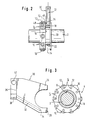
- Fig. 2 zeigt, teils im Schnitt, eine Ansicht eines Stanzzylinders nach Fig. 1 von dessen Schmalseite aus mit zugeordneter Gabel.
- Fig. 3 zeigt eine Seitenansicht eines Stanzzylinders nach Fig. 1 mit zugeordneter Gabel, teilweise im Schnitt.
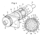
- Fig. 4 zeigt einen Stanzzylinder mit aufgesetzten Stanzsegmenten und zugeordneter Gabel.
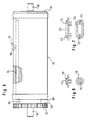
- Fig. 5 zeigt eine Seitenansicht eines Stanzzylinders.
- Fig. 6 zeigt eine geschlossene Stanzkante, in der eine Druckluft-Austrittsöffnung liegt.
- Fig. 7 zeigt eine geschlossene Stanzkante, in der zwei Druckluft-Austrittsöffnungen liegen.
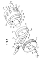
- Fig. 8 zeigt ein Ende eines Stanzzylinders mit einem mit ihm zusammenwirkenden Ring und einem Antriebszahnrad in Explosionsdarstellung.
- Fig. 9 zeigt einen Schnitt längs der Linie IX - IX in Fig. 8 nach Zusammensetzung der in Fig. 8 dargestellten Teile.
- Fig. 10 zeigt einen Kasten zur Aufnahme der ausgestanzten Materialbereiche in seinem Zusammenwirken mit einem Stanzzylinder und einem Widerlagerzylinder.
- Die Figuren 1 bis 3 zeigen eine ortsfest gelagerte, anzutreibende Welle 2, auf der axial verschiebbar und festlegbar zwei scheibenförmige Stanzzylinder 4, 6 drehfest sitzen. Die drehfeste Verbindung wird dadurch bewirkt, daß ein Keil auf der Welle in jeweils eine Nut 8 der Stanzzylinder 4, 6 eingreift.
- Auf der Umfangsfläche der Stanzzylinder 4, 6 befinden sich kreisförmige geschlossene Stanzkanten 10, in denen jeweils eine Austrittsöffnung 12 eines Kanals 14 mündet, der eine in einer Seitenfläche 16 des Stanzzylinders 4, 6 mündende Eintrittsöffnung 18 aufweist. Der Seitenfläche 16 steht ein Flansch 20 an einem zylindrischen Ansatz 22 des Stanzzylinders 4, 6 gegenüber, der einen kleineren Außendurchmesser hat als der Stanzzylinder 4, 6. Der dadurch entstehende Ringraum 24 ist Armen 26, 28 einer Gabel angepaßt, in der sich ein Druckluftzuführungskanal 32 befindet. Dieser Druckluftzuführungskanal 32 endet in einer seitlichen Öffnung 34 des Arms 28 der Gabel 30 und weist am Schaftende 36 der Gabel 30 einen Anschlußstutzen 38 auf, an den ein Druckluftzuführungsschlauch 40 anzuschließen ist. Die Gabel 30 ist mit einem parallel zur Welle 2 verlaufenden Führungsloch 42 versehen, das von einer Welle 44 durchsetzt ist. Die Welle 44 ihrerseits ist relativ zur Welle 2 radial verschiebbar gelagert. Die Gabel 30 kann somit axial und radial zu dem ihr jeweils zugeordneten Stanzzylinder 4 bzw. 6 verschoben werden. Die Gabel 30 ist im Betrieb stationär und der Stanzzylinder 4 bzw. 6 läuft um. Die aus der Öffnung 34 der Gabel 30 austretende Druckluft gelangt somit nacheinander in die Eintrittsöffnungen 18 der kurzen Kanäle 14 und wird, wenn sie beim Übergang von einem Kanal 14 zu einem folgenden Kanal 14 nicht in einer der Eintrittsöffnungen 18 eingeführt werden kann, gestaut. Daraus ergeben sich sehr hohe Druckluftimpulse.
- Fig. 2 zeigt, daß die Eintrittsöffnungen 18 und die Austrittsöffnungen 12 Mündungen von sich rechtwinklig schneidenden, den Kanal bildenden Bohrungen 46 und 48 sind.
- Bei der Ausführungsform nach Fig. 4 ist ein langgestreckter Trägerzylinder 60 von Stanzsegmenten 62 vorgesehen, der axiale Zapfen 64, 66 zur Lagerung aufweist. Am einen Ende des Trägerzylinders 60 befindet sich ein Antriebszahnrad 68, das in axialem Abstand von einer Stirnfläche des Trägerzylinders 60 verläuft und somit Platz für eine Gabel 70 läßt, die grundsätzlich ebenso ausgebildet ist wie die Gabel 30 nach den Fig. 1 bis 3. Für die entsprechenden Elemente sind daher die gleichen Bezugsziffern verwendet. In dem Trägerzylinder verlaufen Axialbohrungen 72, die den Bohrungen 46, und Radialbohrungen 74, die den Radialbohrungen 48 entsprechen. Diese Radialbohrungen 74 koinzidieren mit Bohrungen 76 in den Stanzsegmenten 62. In diesem Fall umschließt jede geschlossene Stanzkante 78 der Stanzsegmente 62 vier Austrittsöffnungen 79.
- Fig. 5 zeigt einen Stanzzylinder 80, an dem nur eine von mehreren geschlossenen Stanzkanten 82 angedeutet ist. Durch den Stanzzylinder 80 erstrecken sich Axialbohrungen 84, die den Axialbohrungen 46 entsprechen, und Radialbohrungen 86, die den Radialbohrungen 48 entsprechen. In Abstand von der Stirnfläche 88 des Stanzzylinders 80 ist über einen zylindrischen Ansatz 90 verringerten Durchmessers ein Zahnrad 92 angesetzt, auf dessen Außenseite sich ein Lagerzapfen 94 befindet. An der anderen Stirnseite 96 des Stanzzylinders 80 ist ebenfalls ein Lagerzapfen 98 angesetzt. Der Raum 100 zwischen der Stirnfläche 88 und dem Zahnrad 92 dient zur Aufnahme der nicht dargestellten Gabel.
- Fig. 6 zeigt eine kreisförmig geschlossene Stanzkante 110, in der zentrisch eine Austrittsöffnung 112 mündet.
- Fig. 7 zeigt eine langgestreckte geschlossene Stanzkante 120, in deren Endbereichen je eine Austrittsöffnung 122, 124 für Druckluft mündet.
- Die Figuren 8 und 9 zeigen einen Stanzzylinder 130 mit vorspringenden geschlossenen Stanzkanten 132, innerhalb denen Austrittsöffnungen 134 für Druckluft münden. Die Druckluft wird den Austrittsöffnungen 134 über Kanäle 136 zugeführt, die innerhalb des Stanzzylinders 130 ausgebildet sind und Eintrittsöffnungen 138 an einer seitlichen Ringfläche 140 des Stanzzylinders 130 aufweisen. Die Ringfläche 140 umschließt einen Zylinderansatz 142 an dem Stanzzylinder 130, dessen Umfangsfläche 144 Lagerfläche für ein Ringteil 146 ist. In der der Ringfläche 140 zugewandten Seitenfläche 148 mündet eine in Umfangsrichtung des Stanzzylinders 130 langgestreckte Öffnung 150, aus der über einen im Ringteil 146 befindlichen Kanal 152 Druckluft den Eintrittsöffnungen 138 der Reihe nach zuzuführen ist. An dem Ringteil 146 ist einstückig ein der Montage dienendes Gabelteil 154 angesetzt. Der Kanal 152 endet eintrittsseitig in einem Innengewindeabschnitt 156, der einen Außengewindeansatz 158 an einem Druckluftzuführungsteil 160 aufnehmen kann. Auf dem zylindrischen Ansatz 152 befindet sich ein zweiter zylindrischer Ansatz 162 verringerten Durchmessers, auf den ein Zahnrad 164 aufgesetzt werden kann. Das Zahnrad 164 ist mittels Schrauben 166, die Löcher 168 im Zahnrad 164 durchsetzen, in Gewindelöchern 170 der Stirnseite des zylindri schen Ansatzes 142 festzuschrauben.
- Fig. 10 zeigt einen Stanzzylinder 180, der mit einem unter ihm angeordneten drehbar gelagerten Widerlagerzylinder 182 zusammenwirkt. Auszustanzendes blattförmiges Material wird durch einen Spalt zwischen dem Stanzzylinder 180 und dem Widerlagerzylinder 182 geführt und anschließend schräg nach oben über eine drehbar gelagerte Stützwalze 186 abgeführt. Zur Aufnahme und Weiterführung der aus dem blattförmigen Material 184 ausgestanzten Materialbereiche ist ein Kasten 188 mit einem auf die jeweils unter Druckluft stehenden Austrittsöffnungen 190 des Stanzzylinders 180 gerichteten Eintrittsschlitz 192 vorgesehen. Der Kasten 188 ist innen als eine Art Labyrinth ausgebildet, an dessen Innenflächen die ausgestanzten Materialbereiche, wie durch ausgezogene Pfeile angedeutet, mehrfach reflektiert werden. Druckluft zieht durch den Kasten teils wirbelförmig, wie durch gestrichelte Pfeile angedeutet. Über einem Bodenbereich 194 des Kastens 188 mündet ein Abzugsstutzen 196 für die ausgestanzten Materialbereiche,der an eine nicht dargestellte Ansaugeinrichtung angeschlossen ist.
- Der Eintrittsschlitz 192 ist unten durch eine etwa tangential schräg nach oben zu dem Widerlagerzylinder 182 gerichtete Wand 198 begrenzt, an der eine die Umfangsfläche 200 des Widerlagerzylinders 182 abstreifende Rakel 202 angesetzt ist. Oben ist der Eintrittsschlitz 192 des Kastens durch eine von dem Stanzzylinder 180 fort weisende Wand 204 begrenzt, die im Querschnitt mit der an sie angrenzenden Wand 206 des Kastens 188 annähernd ein L bildet.
Claims (12)
dadurch gekennzeichnet,
daß die Druckluft aus einer Öffnung (34; 150) in einer Seitenfläche (von 28; 148) eines den Stanzzylinder (4; 6; 60, 62; 80; 130; 180) geführt wenigstens teilweise umgreifenden Teils (30; 70; 146) den Austrittsöffnungen (12; 79; 86; 112; 122, 124; 134; 190) zugeordneten Eintrittsöffnungen (18; 138) zugeführt wird, die sich in einer der Seitenfläche (von 28; 148) dicht anliegenden Seitenfläche (16; 88; 140) des Stanzzylinders.(4; 6; 60, 62; 80; 130; 180) befinden.
Applications Claiming Priority (2)
| Application Number | Priority Date | Filing Date | Title |
|---|---|---|---|
| DE3918470 | 1989-06-06 | ||
| DE3918470A DE3918470A1 (de) | 1989-06-06 | 1989-06-06 | Vorrichtung zum abfuehren von aus einem blattfoermigen material ausgestanzten materialbereichen |
Publications (2)
| Publication Number | Publication Date |
|---|---|
| EP0401769A1 true EP0401769A1 (de) | 1990-12-12 |
| EP0401769B1 EP0401769B1 (de) | 1992-05-13 |
Family
ID=6382196
Family Applications (1)
| Application Number | Title | Priority Date | Filing Date |
|---|---|---|---|
| EP90110648A Expired - Lifetime EP0401769B1 (de) | 1989-06-06 | 1990-06-05 | Vorrichtung zum Abführen von aus einem blattförmigen Material ausgestanzten Materialbereichen |
Country Status (7)
| Country | Link |
|---|---|
| US (1) | US4993293A (de) |
| EP (1) | EP0401769B1 (de) |
| AT (1) | ATE75991T1 (de) |
| CA (1) | CA2014829C (de) |
| DE (2) | DE3918470A1 (de) |
| DK (1) | DK0401769T3 (de) |
| ES (1) | ES2032690T3 (de) |
Cited By (3)
| Publication number | Priority date | Publication date | Assignee | Title |
|---|---|---|---|---|
| EP0667217A1 (de) * | 1994-02-09 | 1995-08-16 | Widia GmbH | Rotationsschneidwerkzeug |
| WO1996009920A1 (en) * | 1994-09-26 | 1996-04-04 | Terpo Holding B.V. | Chain of elastic bands, method and installation for the production of a chain of elastic bands and method and installation for feeding elastic bands from the chain of elastic bands to a handling installation |
| WO2011006992A1 (de) * | 2009-07-16 | 2011-01-20 | WINKLER + DüNNEBIER AG | Folienmesser sowie massivmesserwalze |
Families Citing this family (10)
| Publication number | Priority date | Publication date | Assignee | Title |
|---|---|---|---|---|
| DE4000078A1 (de) * | 1990-01-03 | 1991-07-04 | Winkler Duennebier Kg Masch | Messerwalze |
| WO1992008584A1 (en) * | 1990-11-09 | 1992-05-29 | Rosemann Richard R | Rotary cutting die assembly |
| DK172150B1 (da) * | 1992-05-18 | 1997-12-01 | Ib Groenbjerg | Maskine til at skære en papirbane op i ark under samtidig afskæring af en tværgående strimmel |
| US5704264A (en) * | 1995-08-31 | 1998-01-06 | Kimberly-Clark Worldwide, Inc. | Cutting die with elevated stripping land |
| JP2003104620A (ja) * | 2001-09-28 | 2003-04-09 | Johnson & Johnson Kk | 長尺テープから物品を切出し粘着テープに貼付ける装置 |
| TWM244143U (en) * | 2003-04-16 | 2004-09-21 | Oav Equipment & Tools Inc | Air ejecting and bits blowing apparatus for sawing and cutting machine |
| US20050070415A1 (en) * | 2003-09-30 | 2005-03-31 | Haasl Andrew L. | Assembly for and method of preventing buildup of debris in a folding roll tucker assembly |
| EP2186612A1 (de) | 2008-11-12 | 2010-05-19 | Gerhardt Ltd. | Werkzeug zum Stanzen dünner Platten und Walze zum magnetischen Festhalten des Stanzwerkzeugs |
| DE102009033575B4 (de) * | 2009-07-16 | 2011-07-21 | Winkler+Dünnebier AG, 56564 | Folienmesser mit Saugkammer |
| JP5590865B2 (ja) * | 2009-11-20 | 2014-09-17 | 三菱重工印刷紙工機械株式会社 | ロータリダイカッタの刃物取付台、その固定方法及び装置 |
Citations (4)
| Publication number | Priority date | Publication date | Assignee | Title |
|---|---|---|---|---|
| US4165028A (en) * | 1977-02-14 | 1979-08-21 | Owens-Illinois, Inc. | Method for controlling a web of material |
| DD156234A1 (de) * | 1981-02-09 | 1982-08-11 | Wolfgang Trengel | Verfahren zum pneumatischen auswerfen von stanzgut |
| DE3115688A1 (de) * | 1981-04-18 | 1982-10-28 | Herbert Ing.(Grad.) 4358 Haltern Gawarecki | "vorrichtung zum trennen von im konturenschnitt aus einer materialbahn zu loesenden produkten" |
| US4534248A (en) * | 1982-12-01 | 1985-08-13 | Tetra Pak International Ab | Method and an apparatus for the removal of waste material in rotary punching |
Family Cites Families (4)
| Publication number | Priority date | Publication date | Assignee | Title |
|---|---|---|---|---|
| US3651724A (en) * | 1970-02-09 | 1972-03-28 | Hamilton Tool Co | Method and apparatus for producing card sets |
| NL7002316A (de) * | 1970-02-19 | 1971-08-23 | ||
| DE3417536A1 (de) * | 1984-05-11 | 1985-11-14 | Winkler & Dünnebier, Maschinenfabrik und Eisengießerei GmbH & Co KG, 5450 Neuwied | Verfahren und vorrichtung zum ausschneiden von fenstern in briefumschlaegen |
| IT1186553B (it) * | 1985-01-16 | 1987-12-04 | Gd Spa | Dispositivo di alimentazione di carta in nastro in una macchina confezionatrice di sigarette |
-
1989
- 1989-06-06 DE DE3918470A patent/DE3918470A1/de active Granted
-
1990
- 1990-04-04 US US07/503,934 patent/US4993293A/en not_active Expired - Lifetime
- 1990-04-18 CA CA002014829A patent/CA2014829C/en not_active Expired - Lifetime
- 1990-06-05 DE DE9090110648T patent/DE59000122D1/de not_active Expired - Lifetime
- 1990-06-05 ES ES199090110648T patent/ES2032690T3/es not_active Expired - Lifetime
- 1990-06-05 DK DK90110648.4T patent/DK0401769T3/da active
- 1990-06-05 AT AT90110648T patent/ATE75991T1/de not_active IP Right Cessation
- 1990-06-05 EP EP90110648A patent/EP0401769B1/de not_active Expired - Lifetime
Patent Citations (4)
| Publication number | Priority date | Publication date | Assignee | Title |
|---|---|---|---|---|
| US4165028A (en) * | 1977-02-14 | 1979-08-21 | Owens-Illinois, Inc. | Method for controlling a web of material |
| DD156234A1 (de) * | 1981-02-09 | 1982-08-11 | Wolfgang Trengel | Verfahren zum pneumatischen auswerfen von stanzgut |
| DE3115688A1 (de) * | 1981-04-18 | 1982-10-28 | Herbert Ing.(Grad.) 4358 Haltern Gawarecki | "vorrichtung zum trennen von im konturenschnitt aus einer materialbahn zu loesenden produkten" |
| US4534248A (en) * | 1982-12-01 | 1985-08-13 | Tetra Pak International Ab | Method and an apparatus for the removal of waste material in rotary punching |
Cited By (4)
| Publication number | Priority date | Publication date | Assignee | Title |
|---|---|---|---|---|
| EP0667217A1 (de) * | 1994-02-09 | 1995-08-16 | Widia GmbH | Rotationsschneidwerkzeug |
| WO1996009920A1 (en) * | 1994-09-26 | 1996-04-04 | Terpo Holding B.V. | Chain of elastic bands, method and installation for the production of a chain of elastic bands and method and installation for feeding elastic bands from the chain of elastic bands to a handling installation |
| NL9401561A (nl) * | 1994-09-26 | 1996-05-01 | Terpo Holding Bv | Elastiekketen, werkwijze en inrichting voor het vervaardigen van een elastiekketen, en werkwijze en inrichting voor het aan een behandelinrichting toevoeren van uit de elastiekketen afkomstige elastieken. |
| WO2011006992A1 (de) * | 2009-07-16 | 2011-01-20 | WINKLER + DüNNEBIER AG | Folienmesser sowie massivmesserwalze |
Also Published As
| Publication number | Publication date |
|---|---|
| ES2032690T3 (es) | 1993-02-16 |
| DK0401769T3 (da) | 1992-07-06 |
| DE3918470A1 (de) | 1990-12-13 |
| DE59000122D1 (de) | 1992-06-17 |
| CA2014829A1 (en) | 1990-12-06 |
| CA2014829C (en) | 1996-04-30 |
| EP0401769B1 (de) | 1992-05-13 |
| US4993293A (en) | 1991-02-19 |
| DE3918470C2 (de) | 1993-04-15 |
| ATE75991T1 (de) | 1992-05-15 |
Similar Documents
| Publication | Publication Date | Title |
|---|---|---|
| DE2901886C2 (de) | ||
| EP0401769B1 (de) | Vorrichtung zum Abführen von aus einem blattförmigen Material ausgestanzten Materialbereichen | |
| DE10229406A1 (de) | Vorrichtung zum kontinuierlichen Filtern von Materialgemischen | |
| DE2703610A1 (de) | Zyklonanordnung und verfahren zum beseitigen von verstopfungen bei zyklonanordnungen | |
| DE2935007C2 (de) | Vorrichtung zum kontinuierlichen Herstellen und Fördern von Putzmörtel o.dgl. | |
| DE1536885A1 (de) | Selbstreinigende Filtervorrichtung | |
| DE2606798A1 (de) | Geraet zur pneumatischen entfernung von staub | |
| EP0215476B1 (de) | Rotationsschleifgerät mit Staubabsaugvorrichtung | |
| DE2928093B2 (de) | Vorrichtung zum Abscheiden von Feststoffen aus einem Flüssigkeitsstrom | |
| DE2616894C3 (de) | Schleuderrad | |
| DE3015215A1 (de) | Vorrichtung zur dosierten abgabe eines komprimierten gasfoermigen mediums | |
| DE3142663A1 (de) | "spritzrohr mit flachstrahlduesen" | |
| DE69211126T2 (de) | Vorrichtung zum abzapfen oder abfüllen von flüssigkeiten in einen behälter | |
| DE2622094C3 (de) | Vorrichtung zur Sprühentgasung von Flüssigkeiten | |
| EP1060873A2 (de) | Werkzeuganordnung zur Herstellung von ringförmigen Presslingen mit Hilfe einer Rundläuferpresse | |
| DE3524305C2 (de) | Einzugsvorrichtung | |
| EP0263333A2 (de) | Drall-Luftauslass | |
| DE2836969A1 (de) | Vorrichtung und verfahren zum trennen von mahlkoerpern und mahlgut in einer ruehrwerksmuehle | |
| DE2655935C2 (de) | Aufspreizbare Vorrichtung zum Befestigen von rohrförmigen Wickelhülsen auf Spindeln | |
| DE2641565A1 (de) | Ziehvorrichtung | |
| DE1507791C (de) | Vorrichtung zur Fliehkraftabtrennung von in einem strömenden flüssigen oder gasförmigen Medium mitgeführten feinteiligen festen oder flüssigen Stoffen | |
| DE3111570C2 (de) | Sprühkopf für Sprühgeräte zum Versprühen von unter Druck zugeführten Flüssigkeiten oder anderen fließfähigen Medien | |
| DE2742333C2 (de) | Auflockerungsvorrichtung | |
| DE254234C (de) | ||
| DE29714203U1 (de) | Luftreinigungsgerät und eine Anlage zum Reinigen von Raumluft |
Legal Events
| Date | Code | Title | Description |
|---|---|---|---|
| PUAI | Public reference made under article 153(3) epc to a published international application that has entered the european phase |
Free format text: ORIGINAL CODE: 0009012 |
|
| AK | Designated contracting states |
Kind code of ref document: A1 Designated state(s): AT BE CH DE DK ES FR GB GR IT LI LU NL SE |
|
| 17P | Request for examination filed |
Effective date: 19901213 |
|
| 17Q | First examination report despatched |
Effective date: 19910625 |
|
| GRAA | (expected) grant |
Free format text: ORIGINAL CODE: 0009210 |
|
| AK | Designated contracting states |
Kind code of ref document: B1 Designated state(s): AT BE CH DE DK ES FR GB GR IT LI LU NL SE |
|
| PG25 | Lapsed in a contracting state [announced via postgrant information from national office to epo] |
Ref country code: GR Free format text: LAPSE BECAUSE OF FAILURE TO SUBMIT A TRANSLATION OF THE DESCRIPTION OR TO PAY THE FEE WITHIN THE PRESCRIBED TIME-LIMIT Effective date: 19920513 |
|
| REF | Corresponds to: |
Ref document number: 75991 Country of ref document: AT Date of ref document: 19920515 Kind code of ref document: T |
|
| ITF | It: translation for a ep patent filed | ||
| REF | Corresponds to: |
Ref document number: 59000122 Country of ref document: DE Date of ref document: 19920617 |
|
| REG | Reference to a national code |
Ref country code: DK Ref legal event code: T3 |
|
| ET | Fr: translation filed | ||
| GBT | Gb: translation of ep patent filed (gb section 77(6)(a)/1977) | ||
| REG | Reference to a national code |
Ref country code: ES Ref legal event code: FG2A Ref document number: 2032690 Country of ref document: ES Kind code of ref document: T3 |
|
| PLBE | No opposition filed within time limit |
Free format text: ORIGINAL CODE: 0009261 |
|
| STAA | Information on the status of an ep patent application or granted ep patent |
Free format text: STATUS: NO OPPOSITION FILED WITHIN TIME LIMIT |
|
| 26N | No opposition filed | ||
| EPTA | Lu: last paid annual fee | ||
| EAL | Se: european patent in force in sweden |
Ref document number: 90110648.4 |
|
| REG | Reference to a national code |
Ref country code: GB Ref legal event code: IF02 |
|
| PGFP | Annual fee paid to national office [announced via postgrant information from national office to epo] |
Ref country code: LU Payment date: 20040616 Year of fee payment: 15 Ref country code: AT Payment date: 20040616 Year of fee payment: 15 |
|
| PGFP | Annual fee paid to national office [announced via postgrant information from national office to epo] |
Ref country code: CH Payment date: 20040628 Year of fee payment: 15 |
|
| PG25 | Lapsed in a contracting state [announced via postgrant information from national office to epo] |
Ref country code: AT Free format text: LAPSE BECAUSE OF NON-PAYMENT OF DUE FEES Effective date: 20050605 Ref country code: LU Free format text: LAPSE BECAUSE OF NON-PAYMENT OF DUE FEES Effective date: 20050605 |
|
| PG25 | Lapsed in a contracting state [announced via postgrant information from national office to epo] |
Ref country code: CH Free format text: LAPSE BECAUSE OF NON-PAYMENT OF DUE FEES Effective date: 20050630 Ref country code: LI Free format text: LAPSE BECAUSE OF NON-PAYMENT OF DUE FEES Effective date: 20050630 |
|
| REG | Reference to a national code |
Ref country code: CH Ref legal event code: PL |
|
| REG | Reference to a national code |
Ref country code: GB Ref legal event code: 732E |
|
| BECA | Be: change of holder's address |
Owner name: *GERHARDT INTERNATIONALT A/SKIRSTINEHOJ 3, DK-2770 Effective date: 20070710 |
|
| REG | Reference to a national code |
Ref country code: FR Ref legal event code: TP |
|
| NLS | Nl: assignments of ep-patents |
Owner name: GERHARDT INTERNATIONAL A/S Effective date: 20071115 |
|
| PGFP | Annual fee paid to national office [announced via postgrant information from national office to epo] |
Ref country code: ES Payment date: 20090623 Year of fee payment: 20 Ref country code: DK Payment date: 20090606 Year of fee payment: 20 Ref country code: NL Payment date: 20090615 Year of fee payment: 20 |
|
| PGFP | Annual fee paid to national office [announced via postgrant information from national office to epo] |
Ref country code: FR Payment date: 20090615 Year of fee payment: 20 Ref country code: SE Payment date: 20090608 Year of fee payment: 20 |
|
| PGFP | Annual fee paid to national office [announced via postgrant information from national office to epo] |
Ref country code: BE Payment date: 20090615 Year of fee payment: 20 |
|
| PGFP | Annual fee paid to national office [announced via postgrant information from national office to epo] |
Ref country code: DE Payment date: 20090615 Year of fee payment: 20 Ref country code: GB Payment date: 20090608 Year of fee payment: 20 |
|
| PGFP | Annual fee paid to national office [announced via postgrant information from national office to epo] |
Ref country code: IT Payment date: 20090627 Year of fee payment: 20 |
|
| REG | Reference to a national code |
Ref country code: NL Ref legal event code: V4 Effective date: 20100605 |
|
| REG | Reference to a national code |
Ref country code: DK Ref legal event code: EUP |
|
| BE20 | Be: patent expired |
Owner name: *GERHARDT INTERNATIONALT A/S Effective date: 20100605 |
|
| REG | Reference to a national code |
Ref country code: GB Ref legal event code: PE20 Expiry date: 20100604 |
|
| EUG | Se: european patent has lapsed | ||
| REG | Reference to a national code |
Ref country code: ES Ref legal event code: FD2A Effective date: 20100607 |
|
| PG25 | Lapsed in a contracting state [announced via postgrant information from national office to epo] |
Ref country code: ES Free format text: LAPSE BECAUSE OF EXPIRATION OF PROTECTION Effective date: 20100607 Ref country code: NL Free format text: LAPSE BECAUSE OF EXPIRATION OF PROTECTION Effective date: 20100605 |
|
| PG25 | Lapsed in a contracting state [announced via postgrant information from national office to epo] |
Ref country code: GB Free format text: LAPSE BECAUSE OF EXPIRATION OF PROTECTION Effective date: 20100604 |
|
| PG25 | Lapsed in a contracting state [announced via postgrant information from national office to epo] |
Ref country code: DE Free format text: LAPSE BECAUSE OF EXPIRATION OF PROTECTION Effective date: 20100605 |