EP0401406A1 - Bechersteilförderer zum kontinuierlichen Löschen von Schiffen - Google Patents
Bechersteilförderer zum kontinuierlichen Löschen von Schiffen Download PDFInfo
- Publication number
- EP0401406A1 EP0401406A1 EP89110319A EP89110319A EP0401406A1 EP 0401406 A1 EP0401406 A1 EP 0401406A1 EP 89110319 A EP89110319 A EP 89110319A EP 89110319 A EP89110319 A EP 89110319A EP 0401406 A1 EP0401406 A1 EP 0401406A1
- Authority
- EP
- European Patent Office
- Prior art keywords
- shovelling
- horizontal
- bucket
- ship unloader
- unit frame
- Prior art date
- Legal status (The legal status is an assumption and is not a legal conclusion. Google has not performed a legal analysis and makes no representation as to the accuracy of the status listed.)
- Granted
Links
- 239000011324 bead Substances 0.000 claims description 3
- 238000004140 cleaning Methods 0.000 abstract description 38
- 230000008602 contraction Effects 0.000 description 6
- 238000007665 sagging Methods 0.000 description 5
- 230000003247 decreasing effect Effects 0.000 description 4
- 238000002474 experimental method Methods 0.000 description 2
- 238000005452 bending Methods 0.000 description 1
- 239000003245 coal Substances 0.000 description 1
- 230000010485 coping Effects 0.000 description 1
- 230000008878 coupling Effects 0.000 description 1
- 238000010168 coupling process Methods 0.000 description 1
- 238000005859 coupling reaction Methods 0.000 description 1
- 230000007423 decrease Effects 0.000 description 1
- 238000007599 discharging Methods 0.000 description 1
- 238000000034 method Methods 0.000 description 1
- 238000005096 rolling process Methods 0.000 description 1
- 238000000926 separation method Methods 0.000 description 1
Images


Classifications
-
- B—PERFORMING OPERATIONS; TRANSPORTING
- B65—CONVEYING; PACKING; STORING; HANDLING THIN OR FILAMENTARY MATERIAL
- B65G—TRANSPORT OR STORAGE DEVICES, e.g. CONVEYORS FOR LOADING OR TIPPING, SHOP CONVEYOR SYSTEMS OR PNEUMATIC TUBE CONVEYORS
- B65G21/00—Supporting or protective framework or housings for endless load-carriers or traction elements of belt or chain conveyors
- B65G21/10—Supporting or protective framework or housings for endless load-carriers or traction elements of belt or chain conveyors movable, or having interchangeable or relatively movable parts; Devices for moving framework or parts thereof
- B65G21/14—Supporting or protective framework or housings for endless load-carriers or traction elements of belt or chain conveyors movable, or having interchangeable or relatively movable parts; Devices for moving framework or parts thereof to allow adjustment of length or configuration of load-carrier or traction element
-
- B—PERFORMING OPERATIONS; TRANSPORTING
- B65—CONVEYING; PACKING; STORING; HANDLING THIN OR FILAMENTARY MATERIAL
- B65G—TRANSPORT OR STORAGE DEVICES, e.g. CONVEYORS FOR LOADING OR TIPPING, SHOP CONVEYOR SYSTEMS OR PNEUMATIC TUBE CONVEYORS
- B65G67/00—Loading or unloading vehicles
- B65G67/60—Loading or unloading ships
- B65G67/606—Loading or unloading ships using devices specially adapted for bulk material
Definitions
- the present invention relates to a bucket elevator type continuous ship unloader.
- Cranes used to discharge bulk cargos such as coal, ore or grain from ships with a high degree of efficiency are generally called unloaders.
- Such unloaders are comprised of a glove bucket which grabs a cargo held in a hold and carries it out of the hold.
- Japanese Utility Model Laid-Open No. 62-108339 discloses a bucket elevator type continuous ship unloader which can be used for both a normal sidewise shovelling operation and a catenary cleaning up operation.
- the bucket elevator which runs sidewise (in the direction perpendicular to the plane of Fig. 1, which illustrates a first embodiment of the present invention), with the bucket chain in shovel portion made taut in the horizontal direction.
- the bucket chain is put in the form of a catenary (a loosened state) so as to enable any impact caused by the up-and-down movement of the ship bottom to be absorbed during the cleaning up of the cargo remaining at the bottom.
- a front sprocket is mounted on the forward end of a pivot arm, and the bucket chain is made taut in the horizontal direction or given the form of a catenary by way of the pivot of the pivot arm.
- a guide frame from under which the bucket chain can be inserted is provided, and in operation the bucket chain is inserted in the guide frame so that the force exerted on a bucket in a direction transverse to the direction of the bucket movement can be received by the guide frame.
- An object of the present invention is to provide a bucket elevator type continuous ship unloader which does not require that a bucket chain has to be very taut when a sidewise shovelling operation is to be performed, and which thus allows for use of a light bucket chain having a relatively low degree of rigidity.
- Another object of the present invention is to provide a bucket elevator type continuous ship unloader which ensures a sufficient degree of sag in a catenary state and which is therefore capable of efficiently coping with up-and-down movement of a ship's bottom.
- Another object of the present invention is to provide a bucket elevator type continuous ship unloader which is capable of being readily switched over between a sidewise shovelling operation mode and a catenary cleaning up mode, and which has a simple structure.
- the present invention provides a bucket elevator type continuous ship unloader which includes a horizontal shovelling unit frame, lower front and rear sprockets rotatably supported on the front and rear end portions of the shovelling unit frame, at least one upper sprocket rotatably supported above the rear sprocket, an endless bucket chain wound around the lower front and rear sprockets and the upper sprocket so that it encircles an L-shaped area as seen when looking from the side, a series of buckets mounted on the bucket chain at predetermined intervals, and a means for moving the shovelling unit frame up and down relative to the upper sprocket.
- the continuous ship unloader further includes a roller provided in the vicinity of the portion of each of the buckets through which the bucket is mounted on the bucket.chain, and a horizontal rail provided on the shovelling unit frame along the path of the bucket chain which runs on a straight line between the front and rear sprockets in such a manner that it engages with the roller of each of the buckets, such that the roller runs in a state where it is in engagement with the horizontal rail when the chain is stretched tautly between the front and rear sprockets by the downward movement of the shovelling unit frame, and such that when the shovelling unit frame is moved upward, the roller disengages from the horizontal rail so as to put the bucket chain in a catenary state.
- This ship unloader is a large one in which the interval between the axes of sprockets disposed in the longitudinal direction (in the horizontal direction as viewed in Fig. 1) near a bottom, i.e., the shovelling length, is as long as 6.5 m.
- rollers 2 having a shape similar to that of the beads on an abacus are mounted on a pair of brackets 3 provided at the upper surface of the opposed sides of a bucket 1.
- Rails 4 are horizontally provided in the longitudinal direction over a distance which is substantially the same as or smaller than the distance between the axes of front and rear sprockets.
- the rails 4 are attached to the opposed sides of a horizontal shovelling arm 10 at positions which correspond to the locus of the horizontal rolling of the rollers 2.
- Each of the buckets 1 is fixed to one chain link of each of bucket chains 5 through the bracket 3.
- Front sprockets 6A are supported on the front end (the left end as viewed in Fig.
- sprockets 6C are fixedly provided above the rear sprockets 6B.
- the sprockets 6A, 6B and 6C are disposed so that they form an L-shaped area when they are seen from the side of the ship unloader.
- the horizontal shovelling unit frame 10 is moved up and down by a hydraulic cylinder 7 by virture of a sliding portion 9 thereof being guided along a vertical frame 7A hanging from the forward end of a parallel link boom 20 of a ship unloader.
- a reference numeral 8 denotes a bottom (see Fig. 3), 11 denotes a cargo, and 21 denotes guide rollers.
- Each of the rails 4 has a guide groove having a V-shaped cross-section.
- the guide groove has inclined surfaces 4A and 4B which respectively engage with upper and lower slanted surfaces 2A and 2B formed on the roller 2.
- the rail 4 also has below the V-shaped guide groove a guide surface 4C along which the upper slanted surface 2A of the roller 2 is rolled.
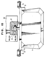
- the guide surface 4C may also be formed as a horizontal surface 4C′ with which the upper horizontal end surface of the roller 2 is brought into contact, as shown in Fig. 10.
- the rail 4 has at each of the longitudinal two end portions thereof (the right and left end portions as viewed in Fig. 1) a guide opening 4D (see Fig. 3), which is formed by the separation of the tapered surfaces 4A and 4B.
- a normal sidewise shovelling operation illustrated in Fig. 1 or 2 is performed by rotating the buckets 1 in a state where the rollers 2 thereof are guided by the rails 4 which are laid horizontally in the longitudinal direction while moving the buckets in the direction perpendicular to the plane of Fig. 1.
- the forces which act on the bucket 1 in a direction transverse to the direction of the bucket movement (in the horizontal direction as viewed in Fig. 7) and in the vertical direction are received by the rails 4.
- the bucket chains 5 which are in the form of a catenary are rotated with the buckets 1 in contact with the bottom 8 so as to shovel or clean up the cargo remaining at the bottom 8. During this cleaning up operation, the up and down movement of the bottom 8 is absorbed by the sagging of the bucket chains 5, and the buckets 1 and/or the bottom 8 are not damaged.
- the ship unloader is returned to the normal sidewise shovelling operation mode from the catenary state shown in Fig. 3 as follows.
- rotation of the bucket chains 5 is stopped, and the horizontal shovelling unit frame 10 is then lowered by the stretching of the hydraulic cylinder 7. This results in stretching of the bucket chains 5.
- the upper slanted surfaces 2A of the rollers 2 are brought into contact with the guide surfaces 4C of the rails 4, as shown in Fig. 8.
- the bucket chains 5 are rotated, and this allows the rollers 2 to be sequentially engaged with the rails 4 at the guide opening 4D formed at the front end portion thereof, thereby returning the ship unloader to a normal sidewise shovelling operation mode.
- the rollers having the form of a bead on an abacus are used.
- the rollers and the rails may be in any form, so long as they are capable of guiding the movement of the buckets and receiving the force exerted on the buckets in the vertical direction as well as in a direction transverse to the direction of the bucket movement.
- the rails 4 are formed on the outer side of the horizontal shovelling unit frame 10. However, they may also be formed on the inner surface of the horizontal shovelling unit frame 10 such that the guide grooves face each other, as shown in Figs. 9 and 10. In the example shown in Fig. 10, it is to be noted that the diameter of the rollers is made slightly smaller than the distance between the two guide grooves.
- the rails receive the force acting on the buckets in the vertical direction and in a direction transverse to the direction of the bucket movement.
- bucket chains need only to pull the buckets, and the bucket chains need not to be as rigid and, hence, heavy as the ones employed in the prior technique.
- the rollers can be sequentially disengaged from or fitted on the rails first by raising or lowering the rails (that is, the horizontal shovelling unit frame) and then by rotating the bucket chains.
- the switching- over operation is very easy and requires no special members, making the entire apparatus simple.
- a sufficient degree of sagging can be provided in a catenary state, and this enables the resultant unloader to efficiently cope with the up-and-down movement of a ship's bottom.
- a closing member 11 may be provided at the front end portion of each of the rails 4 to open and also the guide opening 4D.
- FIG. 11 A first example of the closing member 11 is shown in Fig. 11. This closing member 11 is mounted on the horizontal shovelling unit frame 10 by means of bolts 13. It is removed during a normal sidewise shovelling operation.
- a second example of the closing member 11, which is shown in Fig. 12, is the one which is mounted on the front end portion of the horizontal shovelling unit fame 10 in such a manner as to be pivotal about a pin 14.
- this closing member 11 is pivoted in the direction indicated by the arrow in Fig. 12 so that it is located at position a.
- the closing member 11 is located at position b.
- the closing member 11 located at position b is turned to position c by the rollers 2 which make contact with the closing member 11, so that it guides the rollers 2 downward.
- a third example of the closing member 11 is represented by the one which is pivoted about a pivot 17 by a cylinder 15, which is connected to a coupling portion of the closing member 11. This pivot operation is conducted under control of an operator sitting in an operation seat.
- Provision of the closing members 11 makes a cleaning up operation stable. More specifically, when the cleaning up operation is to be performed, the horizontal shovelling unit frame 10 is lifted by the contraction of the hydraulic cylinder, thereby loosening the portions of each of the bucket chains located above and below the front sprocket 6A, as shown in Fig. 4. Thereafter, the closing members 11 are mounted on the horizontal shovelling unit frame 10 by means of the bolts 13 to close the guide openings 4D, as shown in Fig. 11, or the closing members 11 are made to hang in front of the guide openings 4D and are thereby located at position b, as shown in Fig. 12. Alternatively, the guide openings 4D are closed by means of the closing members 11 by the operation of the cylinder 15, as shown in Fig. 13.
- the guide opening 4D provided at the front end of each of the rails 4 is brought as close to the center O of the front sprockets 6A as possible so that there are separated from each other only by L, whereas the guide opening 4D′ provided at the rear end of the rail is separated as much as possible from the center O′ of the rear sprockets 6B by L′.
- L′ and L are respectively set to values equivalent to one pitch and half pitch of the bucket chain 5.
- each of the rails 4 is located as close to the center O of the front sprocket 6A as possible so that it is separated from the center O only by the distance indicated by L, the rollers 2 are not disengaged from the rails 4 during a sidewise shovelling operation, which would otherwise occur due to the contraction of the hydraulic cylinder 7 caused by the upward movement of a ship's bottom.
- the ship unloader is switched over to a cleaning up operation mode in the manner described below.
- Rotation of the bucket chains 5 is stopped first, and the horizontal shovelling unit frame 10 is then lifted up by the contraction of the hydraulic cylinder 7.
- the distance between the sprockets 6B and 6C decreases because the sprocket 6C is a fixed one, and this loosens the portions of each of the bucket chains 5 located above and below the front sprocket 6A, as shown in Fig. 3.
- the bucket chains 5 are rotated in a reverse direction, as shown in Fig. 14, and this allows the subsequent rollers to be disengaged from the rails 4, as shown in Fig. 15, making the bucket chains 5 assume the form of a catenary shown in Fig. 3.
- the rollers 2 can be disengaged from the rails 4 so as to put each of the bucket chains 5 in the form of a catenary even if the cylinder 7 is contracted by a short length. If L′ is small, the cylinder 7 must be contracted by a large length so as to allow the rollers 2 to be disengaged from the rails 4. When the cylinder 7 is contracted by a large length, the gap h between the upper surface of the horizontal shovelling unit frame 10 and the bucket chain 5 reduces, thus causing interference between these members.
- the bucket chains 5 which are in the form of a catenary are rotated in the forward direction with the buckets 1 being in contact with the bottom 8 of a ship so as to shovel or clean up the cargo remaining at the ship's bottom.
- the up and down movement of the bottom 8 is absorbed by the sagging of the bucket chains 5, and the buckets 1 and/or the bottom 8 are not hence damaged.
- the ship unloader is returned to the normal sidewise shovelling operation mode shown in Fig. 2 from the cleaning up operation mode shown in Fig. 3 in the manner described below.
- rotation of the bucket chains 5 is stopped, and the horizontal shovelling unit frame 10 is then lowered by the stretch of the hydraulic cylinder 7 so as to make the bucket chains 5 taut.
- the upper slanted surfaces 2A of the rollers 2 are brought into contact with the guide surfaces 4C of the rails 4.
- the bucket chains 5 are rotated in the forward direction, and this allows the rollers 2 to be sequentially engaged with the rails 4 near the front sprockets 6A, as shown in Fig. 16, thereby returning the the ship unloader to a normal sidewise shovelling operation mode, as shown in Fig. 17.
- each of the rails is located as close to the center of each of the front sprockets as possible, whereas the rear end portion of the rail is separated as much as possible from the center of the rear sprocket.
- the ship unloader can be switched over easily between a normal sidewise shovelling operation mode and a cleaning up operation mode, and the rollers are not disengaged from the rails during a sidewise shovelling operation.
- the ship unloader can be switched over to a cleaning up operation mode by moving up the horizontal shovelling unit frame through a short distance, interference occurring between the bucket chains and the upper surface of the horizontal shovelling unit frame can be eliminated.
- the guide opening 4D provided at the front end of each of the rails 4 is separated from the center O of each of the sprockets 6A as much as possible by L, and the guide opening 4D′ provided at the rear end of the rail is brought as close to the center O′ of each of the rear sprockets 6B as possible so that they are separated from each other by L′.
- the distance between the front end portion of each of the rails 4 and the center O of each of the front sprockets 6A is made larger than the distance between the rear end portion of each of the rails 4 and the center O′ of each of the rear sprockets 6B.
- L and L′ to be respectively set to values equivalent to one pitch and half pitch of the bucket chain 5.
- a normal sidewise shovelling operation is performed by rotating the buckets 1 in a state where the rollers 2 thereof are guided along the rails 4 that are laid horizontally in the longitudinal direction while moving the buckets in the direction perpendicular to the plane of Fig. 1, as in the first embodiment.
- the ship unloader is switched over to the cleaning up operation mode in the manner described below.
- rotation of the bucket chains 5 is stopped, and the horizontal shovelling unit frame 10 is then lifted by the contraction of the hydraulic cylinder 7. Since the sprockets 6C are the fixed ones, lifting of the horizontal shovelling unit frame 10 reduces the distance between the sprockets 6B and the sprockets 6C, thus loosening the portions of each of the bucket chains 5 located above and below the front sprocket 6A, as shown in Fig. 3.
- the bucket chains 5 can be given the form of a catenary even when the hydraulic cylinder 7 is contracted by a small length. At this time, the distance h between the upper surface of the horizontal shovelling unit frame 10 and the bucket chains 5 does not reduce to a large extent, and interference between the horizontal shovelling unit frame 10 and the bucket chains 5 can be thus eliminated.
- the bucket chains 5 are rotated in the forward direction, and this allows the rollers to be sequentially disengaged from the rails 4, thereby putting the bucket chains 5 in the form of a catenary.
- the ship unloader is returned to a normal sidewise shovelling operation mode shown in Fig. 2 from a catenary state shown in Fig. 3 as follows: First, rotation of the bucket chains 5 is stopped, and the horizontal shovelling unit frame 10 is then lowered by the stretch of the hydraulic cylinder 7. This results in the stretching of the bucket chains 5. So, the upper slanted surfaces 2A of the rollers 2 are brought into contact with the guide surfaces 4C of the rails 4. Thereafter, the bucket chains 5 are rotated in the reverse direction.
- the reverse rotation of the bucket chains 5 allows the rollers 2 to be sequentially and smoothly engaged with the rails near the rear sprockets 6B, thereby returning the ship unloader to a normal sidewise shovelling operation mode.
- each of the rails is separated from the center of each of the front sprockets as much as possible, whereas the rear end portion of the rail is located as close to the center of each of the rear sprockets as possible.
- the ship unloader can be switched over easily between a normal sidewise shovelling operation mode and a cleaning up operation mode.
- the ship unloader can be switched over to a cleaning up operation mode by moving up the horizontal shovelling unit frame through a short distance, and interference occurring between the bucket chains and the upper surface of the horizontal shovelling unit frame can be thus eliminated.
- interference between the rollers and the rails or scoop of the rollers caused by the lifting of the buckets during the cleaning up operation can be eliminated.
- each of the rails is located as close to the center of the rear sprocket as possible, the rollers are engaged with the rails without making the bucket chains very taut, and damage to the rollers and the rails can be eliminated.
- the horizontal rails 4 are laid in the longitudinal direction over a length which is smaller than the distance between the axes of the front and rear sprockets. Furthermore, the openings 4D and 4D′ are respectively formed at the front and rear ends of each of the rails 4, as in the case of other embodiments.
- the present embodiment is characterized in that the horizontal rails 4 are fitted in guide members 17 in such a manner as to be slidable in the longitudinal direction. Each of the guide members 17 is fixed to the outside of the horizontal shovelling unit frame 10.
- a short rack 19 is attached to the upper surface of the outer edge of each of the horizontal rails 4, and this rack 19 is engaged with a pinion 12.
- the pinions 12 are driven by a motor 13 in the forward and reverse directions.
- the motor 13 is mounted on a lateral rib 10a of the horizontal shovelling unit frame 10.
- the power of the motor 13 is transmitted to the pinions 12 through a rotary shaft 15 supported by bearings 14.
- the ship unloader is switched over to the cleaning up operation mode in the manner described below.
- rotation of the bucket chains 5 is stopped, and the horizontal shovelling unit frame 10 is then lifted by the contraction of the hydraulic cylinder 7, thereby reducing the distance between the sprockets 6B and the sprockets 6C (not shown) disposed above the sprockets 6B and loosening the portions of each of the bucket chains 5 located above and below the front sprocket 6A, as shown in Fig. 3.
- the bucket chains 5 are rotated in the forward direction, and this allows the subsequent rollers 2 to be moved on without being fitted in the V-shaped guide grooves 4A and 4B formed in the rails 4, thereby putting the bucket chains 5 in the form of a catenary.
- the cleaning up operation can be performed by rotating the bucket chains 5 which are in the form of a catenary in the forward direction in a state where the buckets 1 are in contact with the bottom 8. During this cleaning up operation, the up and down movement of the bottom 8 is absorbed by the sagging of the bucket chains 5, and the buckets 1 and/or the bottom 8 are not hence damaged.
- the ship unloader is returned to the normal sidewise shovelling operation mode from a catenary state as follows. First, rotation of the bucket chains 5 is stopped, and the horizontal shovelling unit frame 10 is then lowered by the stretch of the hydraulic cylinder 7. This results in the stretching of the bucket chains 5. Next, the bucket chains 5 are rotated in the reverse direction, and this allows the rollers 2 to be sequentially engaged with the horizontal rails 4 at the guide openings 4D′ formed at the rear end portions of the rails.
- the horizontal rails 4 are located as close to the forward sprockets 6A as possible, e.g., the front openings 4D of the horizontal rails 4 are aligned with the center of the front sprockets 6A.
- This is achieved by causing the horizontal rails 4 to slide forward within the guide members 17 by the motor 13 whose driving force is transmitted to the horizontal rails 4 through the rotary shaft 15, the pinions 12 and then the racks 19.
- the rollers 2 can be scooped without fail even if the bucket chains 5 become loosened during the shovelling operation.
- the horizontal rails 4 are located as close to the rear sprockets 6B as possible with the front openings 4D of the horizontal rails 4 separated from the front sprockets 6A as much as possible. In consequence, the possibility of the rollers 4 being scooped by the horizontal rails 4 can be eliminated.
- the ship unloader may also be switched over from the normal sidewise shovelling operation mode to the cleaning up operation mode by separating the rear openings 4D′ of the horizontal rails 4 from the center of the rear sprockets 6B as much as possible and then by rotating the bucket chains 5 in the reverse direction.
- the ship unloader may also be returned to the sidewise shovelling operation mode from the cleaning up operation mode by causing the front openings 4D of the horizontal rails 4 to approach the center of the front sprockets 6A as much as possible and then by rotating the bucket chains 5 in the forward direction.
- the horizontal rails 4 may also be caused to slide in the longitudinal direction by a hydraulic cylinder 16 shown in Fig. 21 through a link 18.
- the horizontal rails into which the rollers provided at the upper end of a bucket are fitted are caused to slide in the longitudinal direction so that they can be moved toward or separated from the front and rear sprockets.
Landscapes
- Engineering & Computer Science (AREA)
- Mechanical Engineering (AREA)
- Ocean & Marine Engineering (AREA)
- Aviation & Aerospace Engineering (AREA)
- Ship Loading And Unloading (AREA)
Priority Applications (3)
| Application Number | Priority Date | Filing Date | Title |
|---|---|---|---|
| DE68920865T DE68920865T2 (de) | 1989-06-07 | 1989-06-07 | Bechersteilförderer zum kontinuierlichen Löschen von Schiffen. |
| EP89110319A EP0401406B1 (de) | 1989-06-07 | 1989-06-07 | Bechersteilförderer zum kontinuierlichen Löschen von Schiffen |
| US04/362,780 US4988250A (en) | 1989-06-07 | 1989-06-07 | Bucket elevator type continuous ship unloader |
Applications Claiming Priority (1)
| Application Number | Priority Date | Filing Date | Title |
|---|---|---|---|
| EP89110319A EP0401406B1 (de) | 1989-06-07 | 1989-06-07 | Bechersteilförderer zum kontinuierlichen Löschen von Schiffen |
Publications (2)
| Publication Number | Publication Date |
|---|---|
| EP0401406A1 true EP0401406A1 (de) | 1990-12-12 |
| EP0401406B1 EP0401406B1 (de) | 1995-01-25 |
Family
ID=8201474
Family Applications (1)
| Application Number | Title | Priority Date | Filing Date |
|---|---|---|---|
| EP89110319A Expired - Lifetime EP0401406B1 (de) | 1989-06-07 | 1989-06-07 | Bechersteilförderer zum kontinuierlichen Löschen von Schiffen |
Country Status (3)
| Country | Link |
|---|---|
| US (1) | US4988250A (de) |
| EP (1) | EP0401406B1 (de) |
| DE (1) | DE68920865T2 (de) |
Cited By (4)
| Publication number | Priority date | Publication date | Assignee | Title |
|---|---|---|---|---|
| WO1992012084A1 (de) * | 1991-01-14 | 1992-07-23 | O&K Orenstein & Koppel Ag | Schiffsbe- oder -entlader |
| DE4311082A1 (de) * | 1993-04-03 | 1994-10-06 | Pwh Anlagen & Systeme Gmbh | Schiffsent- oder -belader |
| EP0748750A1 (de) * | 1995-06-16 | 1996-12-18 | Ishikawajima-Harima Heavy Industries Co., Ltd. | Gerät zum kontinuierlichen Entladen |
| CN113247542A (zh) * | 2021-05-21 | 2021-08-13 | 眉山市科跃工业自动化设备有限公司 | 一种升斗式粪料输送装置 |
Families Citing this family (5)
| Publication number | Priority date | Publication date | Assignee | Title |
|---|---|---|---|---|
| BR9505822A (pt) * | 1994-01-15 | 1996-03-12 | Pwh Anlangen & Systeme Gmbh | Mecacismo de caçambas e extração automática |
| US5564878A (en) * | 1994-11-04 | 1996-10-15 | Texmarc Conveyor Company | Apparatus and method for continuous handling of bulk materials |
| US8205742B2 (en) * | 2008-08-01 | 2012-06-26 | Oxbo International Corporation | Harvester bucket |
| CN106064721B (zh) * | 2016-07-20 | 2024-02-13 | 梁启明 | 滴斗出料装置 |
| CN110255226B (zh) * | 2019-06-11 | 2024-04-26 | 中交第三航务工程勘察设计院有限公司 | 一种门架式链斗卸船机 |
Citations (7)
| Publication number | Priority date | Publication date | Assignee | Title |
|---|---|---|---|---|
| US2897769A (en) * | 1957-11-06 | 1959-08-04 | Mechanical Handling Sys Inc | Multiple choke switch mechanism |
| GB2096087A (en) * | 1981-04-08 | 1982-10-13 | Nat Res Dev | Transfer conveying assembly |
| DE3519780A1 (de) * | 1985-06-03 | 1986-12-04 | Anlagen- Und Filterbau Gmbh & Co Kg, 6342 Haiger | Teleskoptisch |
| EP0212858A1 (de) * | 1985-07-26 | 1987-03-04 | Refac International, Limited | Förder- oder Hebesystem |
| JPS62108339U (de) * | 1985-12-27 | 1987-07-10 | ||
| EP0236845A1 (de) * | 1986-03-12 | 1987-09-16 | Fried. Krupp Gesellschaft mit beschränkter Haftung | Steilförderer, insbesondere für die Schiffsentladung |
| GB2205800A (en) * | 1987-04-24 | 1988-12-21 | Sumitomo Heavy Industries | Bucket elevator-type continuous unloader |
Family Cites Families (9)
| Publication number | Priority date | Publication date | Assignee | Title |
|---|---|---|---|---|
| JPS5751622A (en) * | 1980-09-10 | 1982-03-26 | Hitachi Ltd | Continuous unloader |
| US4917234A (en) * | 1984-11-14 | 1990-04-17 | Seymour Timothy H | Wheel and chain power transmission machine |
| JPS62108339A (ja) * | 1985-11-06 | 1987-05-19 | Nippon Denso Co Ltd | 電子回路の異常監視装置 |
| JPH0312749Y2 (de) * | 1985-12-20 | 1991-03-26 | ||
| US4838410A (en) * | 1987-06-11 | 1989-06-13 | Refac International, Limited | Chain and chain track for rotating conveyor bucket |
| JP2651829B2 (ja) * | 1987-12-09 | 1997-09-10 | 住友重機械工業株式会社 | バケットエレベータ式連続アンローダ |
| JPH01150613A (ja) * | 1987-12-09 | 1989-06-13 | Sumitomo Heavy Ind Ltd | バケットエレベータ式連続アンローダ |
| JPH0781690B2 (ja) * | 1990-03-15 | 1995-09-06 | 株式会社タクマ | バガスボイラの過熱水蒸気の温度制御方法 |
| JPH03267607A (ja) * | 1990-03-16 | 1991-11-28 | Matsushita Electric Ind Co Ltd | 燃焼装置 |
-
1989
- 1989-06-07 DE DE68920865T patent/DE68920865T2/de not_active Expired - Fee Related
- 1989-06-07 EP EP89110319A patent/EP0401406B1/de not_active Expired - Lifetime
- 1989-06-07 US US04/362,780 patent/US4988250A/en not_active Expired - Fee Related
Patent Citations (7)
| Publication number | Priority date | Publication date | Assignee | Title |
|---|---|---|---|---|
| US2897769A (en) * | 1957-11-06 | 1959-08-04 | Mechanical Handling Sys Inc | Multiple choke switch mechanism |
| GB2096087A (en) * | 1981-04-08 | 1982-10-13 | Nat Res Dev | Transfer conveying assembly |
| DE3519780A1 (de) * | 1985-06-03 | 1986-12-04 | Anlagen- Und Filterbau Gmbh & Co Kg, 6342 Haiger | Teleskoptisch |
| EP0212858A1 (de) * | 1985-07-26 | 1987-03-04 | Refac International, Limited | Förder- oder Hebesystem |
| JPS62108339U (de) * | 1985-12-27 | 1987-07-10 | ||
| EP0236845A1 (de) * | 1986-03-12 | 1987-09-16 | Fried. Krupp Gesellschaft mit beschränkter Haftung | Steilförderer, insbesondere für die Schiffsentladung |
| GB2205800A (en) * | 1987-04-24 | 1988-12-21 | Sumitomo Heavy Industries | Bucket elevator-type continuous unloader |
Non-Patent Citations (1)
| Title |
|---|
| PATENT ABSTRACTS OF JAPAN, vol. 8, no. 170 (M-315)[1607], 7th August 1984; & JP-A-59 64 406 (HITACHI) 12-04-1984 * |
Cited By (5)
| Publication number | Priority date | Publication date | Assignee | Title |
|---|---|---|---|---|
| WO1992012084A1 (de) * | 1991-01-14 | 1992-07-23 | O&K Orenstein & Koppel Ag | Schiffsbe- oder -entlader |
| US5409343A (en) * | 1991-01-14 | 1995-04-25 | O&K Orenstein & Koppel Ag | Ship loader or unloader |
| DE4311082A1 (de) * | 1993-04-03 | 1994-10-06 | Pwh Anlagen & Systeme Gmbh | Schiffsent- oder -belader |
| EP0748750A1 (de) * | 1995-06-16 | 1996-12-18 | Ishikawajima-Harima Heavy Industries Co., Ltd. | Gerät zum kontinuierlichen Entladen |
| CN113247542A (zh) * | 2021-05-21 | 2021-08-13 | 眉山市科跃工业自动化设备有限公司 | 一种升斗式粪料输送装置 |
Also Published As
| Publication number | Publication date |
|---|---|
| US4988250A (en) | 1991-01-29 |
| EP0401406B1 (de) | 1995-01-25 |
| DE68920865T2 (de) | 1995-06-14 |
| DE68920865D1 (de) | 1995-03-09 |
Similar Documents
| Publication | Publication Date | Title |
|---|---|---|
| US4988250A (en) | Bucket elevator type continuous ship unloader | |
| CN211769074U (zh) | 一种履带移动式伸缩装船系统 | |
| US3756375A (en) | Material handling apparatus | |
| US4890719A (en) | Excavator for bucket elevator type continuous unloader | |
| CN1008994B (zh) | 斗式提升连续卸料机 | |
| CN115404932B (zh) | 一种清污设备 | |
| CN207259094U (zh) | 一种带轨道的垂直提升布料机 | |
| CN213445266U (zh) | 一种链斗卸船机 | |
| JP2001122444A (ja) | 連続アンローダ | |
| US5232327A (en) | Ship loader or unloader | |
| JPH01150613A (ja) | バケットエレベータ式連続アンローダ | |
| KR0145185B1 (ko) | 버키트 엘리베이터식 연속 쉽언로우더 | |
| US3847270A (en) | Material digging and transporting apparatus | |
| CN111252575A (zh) | 一种履带移动式伸缩装船系统 | |
| CN1020574C (zh) | 斗式提升机式船舶连续卸载机 | |
| CN113123634A (zh) | 一种全自动智能化屋面维修系统 | |
| CN115724226B (zh) | 一种门架式链斗卸船机 | |
| JPH0743064Y2 (ja) | バケットエレベータ式連続アンローダ | |
| JP2709599B2 (ja) | バケットエレベータ式連続アンローダ | |
| CN208699825U (zh) | 升降刮板机 | |
| JP2651829B2 (ja) | バケットエレベータ式連続アンローダ | |
| JPH01261127A (ja) | バケットエレベータ式連続アンローダ | |
| JP2912192B2 (ja) | ベルト式アンローダ | |
| JPS63267607A (ja) | バケツトエレベ−タ式連続アンロ−ダ | |
| CN2375666Y (zh) | 反抓式电动清污机 |
Legal Events
| Date | Code | Title | Description |
|---|---|---|---|
| PUAI | Public reference made under article 153(3) epc to a published international application that has entered the european phase |
Free format text: ORIGINAL CODE: 0009012 |
|
| AK | Designated contracting states |
Kind code of ref document: A1 Designated state(s): DE FR GB IT NL |
|
| 17P | Request for examination filed |
Effective date: 19910503 |
|
| 17Q | First examination report despatched |
Effective date: 19920825 |
|
| GRAA | (expected) grant |
Free format text: ORIGINAL CODE: 0009210 |
|
| AK | Designated contracting states |
Kind code of ref document: B1 Designated state(s): DE FR GB IT NL |
|
| ITF | It: translation for a ep patent filed | ||
| REF | Corresponds to: |
Ref document number: 68920865 Country of ref document: DE Date of ref document: 19950309 |
|
| ET | Fr: translation filed | ||
| PGFP | Annual fee paid to national office [announced via postgrant information from national office to epo] |
Ref country code: GB Payment date: 19950524 Year of fee payment: 7 |
|
| PGFP | Annual fee paid to national office [announced via postgrant information from national office to epo] |
Ref country code: NL Payment date: 19950627 Year of fee payment: 7 Ref country code: DE Payment date: 19950627 Year of fee payment: 7 |
|
| PGFP | Annual fee paid to national office [announced via postgrant information from national office to epo] |
Ref country code: FR Payment date: 19950629 Year of fee payment: 7 |
|
| PLBE | No opposition filed within time limit |
Free format text: ORIGINAL CODE: 0009261 |
|
| STAA | Information on the status of an ep patent application or granted ep patent |
Free format text: STATUS: NO OPPOSITION FILED WITHIN TIME LIMIT |
|
| 26N | No opposition filed | ||
| PG25 | Lapsed in a contracting state [announced via postgrant information from national office to epo] |
Ref country code: GB Effective date: 19960607 |
|
| PG25 | Lapsed in a contracting state [announced via postgrant information from national office to epo] |
Ref country code: NL Effective date: 19970101 |
|
| GBPC | Gb: european patent ceased through non-payment of renewal fee |
Effective date: 19960607 |
|
| PG25 | Lapsed in a contracting state [announced via postgrant information from national office to epo] |
Ref country code: FR Effective date: 19970228 |
|
| PG25 | Lapsed in a contracting state [announced via postgrant information from national office to epo] |
Ref country code: DE Effective date: 19970301 |
|
| NLV4 | Nl: lapsed or anulled due to non-payment of the annual fee |
Effective date: 19970101 |
|
| REG | Reference to a national code |
Ref country code: FR Ref legal event code: ST |
|
| PG25 | Lapsed in a contracting state [announced via postgrant information from national office to epo] |
Ref country code: IT Free format text: LAPSE BECAUSE OF NON-PAYMENT OF DUE FEES;WARNING: LAPSES OF ITALIAN PATENTS WITH EFFECTIVE DATE BEFORE 2007 MAY HAVE OCCURRED AT ANY TIME BEFORE 2007. THE CORRECT EFFECTIVE DATE MAY BE DIFFERENT FROM THE ONE RECORDED. Effective date: 20050607 |